HHB CDR-850 Service Manual
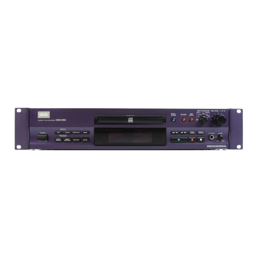
Professional compact disc recorder
Hide thumbs
Also See for CDR-850:
- Operating instructions manual (128 pages) ,
- Service manual (88 pages)
Table of Contents
Advertisement
THIS MANUAL IS APPLICABLE TO THE
FOLLOWING MODEL(S) AND TYPE(S).
Model
Type
Power Requirement
CDR-850
KU/CA
MY
FOR U.S. MODELS
NECESSARY INFORMATION FOR DHHS
RULES MARKED ON THE REAR BASE AND ON
THE TOP OF CD MECHANISM AS BELOW.
DANGER – LASER RADIATION WHEN OPEN.
AVOID DIRECT EXPOSURE TO BEAM.
Remarks
AC120V
AC220-230V
Advertisement
Table of Contents

Related Manuals for HHB CDR-850


Summary of Contents for HHB CDR-850
- Page 1 THIS MANUAL IS APPLICABLE TO THE FOLLOWING MODEL(S) AND TYPE(S). Model Type Power Requirement Remarks CDR-850 KU/CA AC120V AC220-230V FOR U.S. MODELS NECESSARY INFORMATION FOR DHHS RULES MARKED ON THE REAR BASE AND ON THE TOP OF CD MECHANISM AS BELOW.
-
Page 2: Safety Information
CDR-850 1. SAFETY INFORMATION This service manual is intended for qualified service technicians ; it is not meant for the casual do-it- yourselfer. Qualified technicians have the necessary test equipment and tools, and have been trained to properly and safely repair complex products such as those covered by this manual. -
Page 3: Table Of Contents
CDR-850 LABEL CHECK MY Type MY Type MY Type Printed on Rear Panel KU/CA type Printed on Rear Panel Additional Laser Caution 1. Laser Interlock Mechanism The position of the switch (S601) for detecting loading state is detected by the system microprocessor, and the... -
Page 4: Exploded Views And Parts List
8 Dry Cell Battery (R03,AAA) VEM-022 9 Polyethylene Bag RHL1024 Packing Case PHG2365 (2) CONTRAST TABLE CDR-850/MY and KU/CA are constructed the same except for the following : Part No. Mark No. Symbol and Description Remarks CDR-850/MY CDR-850/KU/CA AC Power Cord... - Page 5 CDR-850 2.2 EXTERIOR SECTION KU/CA Type only KU/CA Type only KU/CA Type only Refer to "2.4 LOADING MECHANISM ASSY". No Supplied Part Accessories for the INPUT ASSY 38 MY Type only Refer to "2.3 FRONT PANEL SECTION".
- Page 6 PMZ30P060FCC Screw BBZ30P080FCC Rivet RBM-003 Screw IBZ30P060FCC Fuse Cover PNM1343 (2) CONTRAST TABLE CDR-850/MY and KU/CA are constructed the same except for the following : Part No. Mark No. Symbol and Description Remarks CDR-850/MY CDR-850/KU/CA SERVO DIGITAL Assy PWM2219 PWM2220...
-
Page 7: Front Panel Section
CDR-850 2.3 FRONT PANEL SECTION Accessories for the VR ASSY. • FRONT PANEL SECTION PARTS LIST Mark No. Description Part No. Mark No. Description Part No. FUNCTION Assy PYY1266 Display Window H PAM1794 HEADPHONE Assy PWZ3715 LED Lens PNW2745 VR Assy... - Page 8 CDR-850 2.4 LOADING MECHANISM ASSY • Bottom View Loading Base • LOADING MECHANISM ASSY PARTS LIST Mark No. Description Part No. Mark No. Description Part No. 1 32P F•F•C/30V PDD1187 Lock Plate VNL1820 2 Earth Lead Unit PDF1088 Tray Stopper...
-
Page 9: Bottom View
CDR-850 2.5 SERVO MECHANISM ASSY • Bottom View SERVO MECH ASSY Carriage Base S How to Install the Disc Table Use nippers or other tool to cut the two sections marked in figure While supporting the spindle motor shaft with the stopper, put spacer on top of the carriage base, and stick the disc table on top (takes about 9kg pressure). -
Page 10: Schematic Diagram
CDR-850 3. SCHEMATIC DIAGRAM 3.1 OVERALL CONNECTIONS, LOADING A, B, and SERVO MECH ASSEMBLIES CD-R PICUP ASSY PEA1351 SERVO DIGITAL ASSY (PWM2219 : MY) (PWM2220 : KU/CA) PEA1350 SERVO PEA1235 MECH ASSY (PWZ3758) LOADING B ASSY (PWZ3728) VXX2505 PC651 NJL5803K–F1... - Page 11 CDR-850 Note : When ordering service parts, be sure to refer to "EXPLODED VIEWS and PARTS LIST" or "PCB PARTS LIST". HEADPHONE ASSY (PWZ3715) 1/2, AUDIO ASSY (PWZ3933: MY) (PWZ3934: KU/CA) INPUT ASSY (PWZ3929: MY) (PWZ3930: KU/CA) POWER ASSY (PWZ3937: MY)
- Page 12 CDR-850 3.2 SERVO DIGITAL ASSY(1/6) ATIP DECODER...
- Page 13 CDR-850 MECH.CONTROL MICOM BLOCK SERVO DIGITAL ASSY(1/6) (PWM2219 : MY) (PWM2220 : KU/CA) • MECH. CONTROL MICOM BLOCK 8BIT LATCH CN701...
- Page 14 CDR-850 3.3 SERVO DIGITAL(2/6) and PICKUP ASSEMBLIES SERVO DIGITAL ASSY(2/6) (PWM2219 : MY) (PWM2220 : KU/CA) • RF PROCESSOR BLOCK CD-R PICUP ASSY PEA1351...
- Page 15 CDR-850 MY TYPE ONLY...
- Page 16 CDR-850 3.4 SERVO DIGITAL ASSY(3/6)
- Page 17 CDR-850 SERVO DIGITAL ASSY(3/6) (PWM2219 : MY) (PWM2220 : KU/CA) • SERVO BLOCK CDR SERVO AMP...
- Page 18 CDR-850 3.5 SERVO DIGITAL ASSY(4/6) INPUT INPUT...
- Page 19 CDR-850 SERVO DIGITAL ASSY(4/6) (PWM2219 : MY) (PWM2220 : KU/CA) • DIGITAL BLOCK OUTPUT OUTPUT J801...
- Page 20 CDR-850 3.6 SERVO DIGITAL ASSY(5/6) SERVO DIGITAL ASSY(5/6) (PWM2219 : MY) (PWM2220 : KU/CA) • DECODER BLOCK...
- Page 21 CDR-850...
- Page 22 CDR-850 3.7 SERVO DIGITAL ASSY(6/6) SERVO DIGITAL ASSY(6/6) (PWM2219 : MY) (PWM2220 : KU/CA) • STRATEGY BLOCK KU/CA TYPE ONLY R1323 : 0 (MY TYPE) L323 : QTL1015 (KU/CA TYPE)
- Page 23 CDR-850...
- Page 24 CDR-850 3.8 AUDIO(1/2) and HEADPHONE ASSEMBLIES D/A CONVERTER...
- Page 25 CDR-850 • AUDIO ASSY(1/2) D/A BLOCK (PWZ3933 : MY) (PWZ3934 : KU/CA) : AUDIO SIGNAL ROUTE HEADPHONE ASSY (PWZ3715)
- Page 26 CDR-850 3.9 AUDIO(2/2) and VR ASSEMBLIES VR ASSY (PWZ3719)
- Page 27 CDR-850 : AUDIO SIGNAL ROUTE AUDIO ASSY(2/2) (PWZ3933 : MY) (PWZ3934 : KU/CA) • A/D BLOCK A/D CONVERTER...
- Page 28 CDR-850 3.10 POWER and TRANS ASSEMBLIES AC POWER CORD 1P AC INLET • NOTE FOR FUSE REPLACEMENT (10000p/250) (10000p/250) (10000p/250) POWER TRANSFORMER C901 C902 C903 C904 C905 C906 C907 C908 C909 TRANS ASSY (PWZ3752)
- Page 29 CDR-850 POWER ASSY (PWZ3937 : MY) (PWZ3938 : KU/CA) J701 CN402 CN8003 CN355 CAUTION : FOR CONTINUED PROTECTION AGAINST RISK OF FIRE. REPLACE ONLY WITH SAME TYPE NO. ICP-N15, MFD BY ROHM CO., LTD. FOR IC22,IC23,IC25.
- Page 30 CDR-850 3.11 FUNCTION ASSY FL HOLDER REMOTE RECEIVER UNIT FUNCTION ASSY (PWZ3699) FUNCTION ASSY S702 : PLAY 3 S703 : PAUSE 8 S704 : STOP 7 S705 : TRACK SEARCH 4 1 S706 : TRACK SEARCH ¡ ¢ S707 : OPEN/CLOSE...
- Page 31 CDR-850 CN202 MODE CONTROLLER R710–R715 : ACN7081 SYSTEM RESET Q701–Q704 : DTA114EK...
- Page 32 CDR-850 3.12 INPUT ASSY...
- Page 33 CDR-850 INPUT ASSY (PWZ3929 : MY) (PWZ3930 : KU/CA) J8006 J407, J408 J408 CN302...
-
Page 34: Pcb Connection Diagram
CDR-850 4. PCB CONNECTION DIAGRAM NOTE FOR PCB DIAGRAMS : 1. Part numbers in PCB diagrams match those in the schematic 3. The parts mounted on this PCB include all necessary parts for diagrams. several destinations. 2. A comparison between the main parts of PCB and schematic For further information for respective destinations, be sure to diagrams is shown below. - Page 35 CDR-850 4.1 LOADING A, LOADING B and SERVO MECH ASSEMBLIES SIDE A SIDE B LOADING A ASSY CN352 LOADING B ASSY (PNP1447-B) SERVO MECH ASSY (PNP1447-B) CN353...
- Page 36 CDR-850 4.2 SERVO DIGITAL ASSY PICKUP CN501 ASSY SERVO DIGITAL ASSY CN601 CN701 VR101 VR107 VR108 VR104 VR102 VR103 VR106 VR105 IC351 Q107 Q102 IC243 IC248 IC245 IC212 IC352 Q106 Q101 IC103 IC101 IC249 IC250 IC213 IC206 IC355 Q250 IC247...
- Page 37 CDR-850 J801 CN3002 VR301 (PNP1445-G) IC353 IC301 IC308 IC311 IC318 IC201 IC302 IC309 IC310 IC205 IC204 IC303 IC202 IC316 IC314 Q301 Q203...
- Page 38 CDR-850 SERVO DIGITAL ASSY (PNP1445-G) IC305 Q302 IC354 Q351 IC313 IC320 Q303 Q201 IC312 Q204 IC207 IC203 SIDE B...
- Page 39 CDR-850 IC246 Q242 IC105 Q201 Q241 IC102 Q104 IC104 Q105 IC210 IC208 Q103...
- Page 40 CDR-850 4.3 AUDIO, HEADPHONE and VR ASSEMBLIES CN8101 CN8102 VR ASSY Q407 Q408 Q406 Q405 IC803 IC804 (PNP1456-D) IC404 CN8005 CN8004 CN301 IC451 CN8101 (PNP1463-B) AUDIO ASSY HEADPHONE ASSY SIDE A (PNP1456-D) E F G...
- Page 41 CDR-850 VR ASSY AUDIO ASSY Q404 Q409 Q403 (PNP1456-D) IC406 IC401 IC801 Q401 IC402 Q402 (PNP1463-B) HEADPHONE ASSY SIDE B (PNP1456-D)
- Page 42 CDR-850 4.4 POWER and TRANS ASSEMBLIES AC POWER CORD CN8003 POWER ASSY NEUTRAL LIVE CN402 IC37 IC33 IC21 IC36 IC23 IC32 IC31 IC35 CN355 IC25 IC24 (PNP1463-B) J701 SIDE A POWER (PNP1456-D) TRANSFORMER TRANS ASSY...
- Page 43 CDR-850 POWER ASSY (PNP1463-B) TRANS ASSY SIDE B (PNP1456-D)
- Page 44 CDR-850 4.5 FUNCTION ASSY FUNCTION ASSY CN202 SIDE A IC705 Q705 IC702 FUNCTION ASSY SIDE B IC701...
- Page 45 CDR-850 CN51 CN8006 (PNP1456-D) IC704 Q706 Q701 Q704...
- Page 46 CDR-850 INPUT ASSY 4.6 INPUT ASSY IC3001 CN302 Q408 CN805 Q8009 Q8010 CN803 J708 Q8101 J407, J408 Q8102 J408 SIDE A (PNP1463-B)
- Page 47 CDR-850 INPUT ASSY Q8002 Q8004 Q8007 Q8003 Q8006 Q8005 IC8001 IC8003 Q8202 Q8201 IC8101 IC8103 IC8105 Q8103 IC8102 IC8104 IC8106 Q8104 Q3705 Q3706 Q3707 Q3708 Q3701 SIDE B Q3702 Q3703 Q3704 (PNP1463-B)
-
Page 48: Pcb Parts List
CDR-850 Mark No. Description Part No. Mark No. Description Part No. 5. PCB PARTS LIST • NOTES: Parts marked by "NSP" are generally unavailable because they are not in our Master Spare Parts List. • mark found on some component parts indicates the importance of the safety factor of the part. - Page 49 CDR-850 Mark No. Description Part No. Mark No. Description Part No. L313, L314, L317, L318 QTL1015 (2) PARTS LIST FOR PWM2219 L320, L321, L351, L352 QTL1015 SEMICONDUCTORS IC311 AD1893JST CAPACITORS IC103 AK8563 C120 CCSQCH100D50 IC201 BA05T C306, C316, C325, C326, C338...
- Page 50 CDR-850 Mark No. Description Part No. Mark No. Description Part No. C145, C199, C201, C202 CKSQYF103Z50 Q403 DTA124EK C207, C208, C234, C240, C250 CKSQYF103Z50 Q401, Q404 DTC124EK C301, C302 CKSQYF103Z50 D401–D404 1SS133 C101, C105, C109, C113, C121 CKSQYF104Z25 D407, D408...
- Page 51 CDR-850 Mark No. Description Part No. Mark No. Description Part No. PCB BINDER VEF1040 CKSQYF104Z50 KN111, KN112, KN114 VNF1084 C15, C24 CKSQYF473Z50 EARTH METAL FITTING C32, C33 CQMA223J50 C55, C56 CQMA273J50 (1000µF/16V) PCH1122 HEADPHONE ASSY (100µF/50V) PCH1126 C34, C35 (4.7µF/50V)
- Page 52 CDR-850 Mark No. Description Part No. Mark No. Description Part No. SWITCHES AND RELAYS CAPACITORS S720 PSB1008 C8111–C8114 CCSQCH101J50 S702–S719 VSG1009 C3006 CCSQCH331J50 C3002, C3003, C8101–C8104 CCSQCH470J50 C8123, C8124, C8127, C8128 CCSQCH470J50 CAPACITORS C8011, C8012 CEAT101M25 C701 CCSQCH101J50 C743 CCSQCH470J50 C8105–C8108...
-
Page 53: Adjustment
CDR-850 6. ADJUSTMENT 6.3.2 Operations in Test Mode 6.1 DISCS TO BE USED In Test mode, the following adjustment functions are assigned to 1. When adjusting the servo system adjustment the buttons, as explained below. CD : Test disc for adjustment (STD-903 or equivalent) ¶... - Page 54 CDR-850 6.4 ADJUSTMENT 1 (LASER DIODE POWER ADJUSTMENT) SERVO DIGITAL ASSY CD-RW record power CD-R overdrive CD-R record power Playback power CD-RW bias power CN354 Playback CD-R recording CD-RW recording CD-RW erase CN102 power VR105 Fig.5 Output power of the laser diode RW REC.
- Page 55 CDR-850 DANGER – LASER RADIATION WHEN OPEN. AVOID DIRECT EXPOSURE TO BEAM. 6.4.2 CD-R Record Power Adjustment Test Point Pickup objective lens Adjustment Point VR102 (R REC. PW1), VR103 (R REC. PW2) VR102 : 4.60 mW ± 0.1 mW Adjustment Value VR103 : Addition of 0.1 mW ±...
- Page 56 CDR-850 6.5 ADJUSTMENT 2 (SERVO SYSTEM ADJUSTMENT) SERVO DIGITAL ASSY For servo adjustment, set the INPUT SELECTOR to OPTICAL. CN354 (TP201) Use the RECORD and REC MUTE buttons to make the adjustments. CN354 1 : RF CN102 2 : TE...
- Page 57 CDR-850 6.5.2 M-S Mix Ratio Adjustment Test Point CN102 - pin 3 (TE) and pin 4 (MPP) Adjustment Point RECORD button and REC MUTE button Adjustment Value Adjust until the value of the output signals from pin 3 (TE) and pin 4 (MPP) of CN102 are the same, or the differential output of these signals is minimal.
- Page 58 CDR-850 6.5.4 Focus Bias Adjustment Test Point CN354 - pin 1 (RF) Adjustment Point DIGITAL SYNCHRO button, RECORD button and REC MUTE button Adjustment Value Adjust until RF jitter is minimal or that the eye pattern of the RF waveform is most open.
-
Page 59: General Information
CDR-850 7. GENERAL INFORMATION 7.1 PARTS 7.1.1 IC • The information shown in the list is basic information and may not correspond exactly to that shown in the schematic diagrams. • List of IC NJM2136M, MC34072D, AK8563, BA7082F, AD1893JST, BA5912AFP-Y, BA5932FP, CXD2585Q,... - Page 60 CDR-850 AK8563 (SERVO DIGITAL ASSY : IC103) • RF Processor IC • Pin Assignment (Top view) 60 59 58 57 56 55 54 53 52 51 50 49 48 47 46 45 44 43 42 41 AVDD1 61 AVSS2 RECDIN 62...
- Page 61 CDR-850 • Block Diagram 29 30 56 55 63 28 27 26 57 53 54 11 10 SRFO HAVC RF_EQUALIZER FOCUS & XTAND TRACK MPDSH XTOR SPPO AGCON GAINUP2 MATRIX SPDSH GAINUP3 ATFM ATIP SADBC ATFG AGC1C AGC2C RFOM WBLSH...
- Page 62 CDR-850 • Pin Function v i t v i t t s i L " : " z i l t s i L " : " " : " t s i " : " L " : "...
-
Page 63: Block Diagram
CDR-850 BA7082F (SERVO DIGITAL ASSY : IC302) • VCO IC • Block Diagram VCTL 1/2FB FOUT • Pin Function − e l l − l i b y t i − t i c l l i l i b... - Page 64 CDR-850 BA5912AFP-Y (SERVO DIGITAL ASSY : IC351) • Driver IC • Block Diagram 10kΩ 10kΩ 10kΩ 10kΩ T.S.D. LEVEL LEVEL SHIFT SHIFT Vref1 Vref1 Vref2 Vref2 REF1 REF2 SWITCH SWITCH 10kΩ 10kΩ 10kΩ 10kΩ 10kΩ 10kΩ 10kΩ 10kΩ MUTE MUTE •...
- Page 65 CDR-850 BA5932FP (SERVO DIGITAL ASSY : IC352) • Driver IC • Block Diagram 10kΩ LOADING × 1 × 1 10kΩ 10kΩ 10kΩ 10kΩ LOADING 10kΩ 10kΩ × 1 × 1 10kΩ 10kΩ 10kΩ • Pin Function v i t –...
- Page 66 CDR-850 CXD2585Q (SERVO DIGITAL ASSY : IC353) • Digital Signal Processor IC • Pin Assignment (Top view) ASYE DOUT TES1 LRCK TEST PCMD FRDR EMPH FFDR XTSL TRDR TFDR XTAI SRDR XTAO SFDR SOUT SOCK FSTO XOLT SSTP SQSO SQCK...
- Page 67 CDR-850 • Block Diagram 11 13 68 10 17 14 65 66 67 TES1 TEST Clock FSTO Error XRST Generator Corrector Demodulator Interface RFAC ASYI Asymmetry ASYO Corrector ASYE BIAS XPCK Sub Code Digital FILO Processor Digital DOUT FILI CLTV...
- Page 68 CDR-850 • Pin Function − " " L " " l a i − l a i n i l l a i i f i l − l a i l l u L " = " " , = "...
- Page 69 CDR-850 TK11041M-1 (SERVO DIGITAL ASSY : IC355) • Thermo Sensor IC • Block Diagram Temperature × 1 Sensor S-806E (FUNCTION ASSY : IC702) • Voltage Detector IC • Block Diagram...
- Page 70 CDR-850 PE8001A (AUDIO ASSY : IC401) • D/A Converter IC • Block Diagram 20 19 9 10 Serial Low-pass Input Filter LRCK Multi-level Oversampling DATA Delta-Sigma EXTL Digital Filter Modulator Low-pass with Filter Function ML/IIS Controller EXTR MC/DM1 MD/DM0 Mode...
- Page 71 CDR-850 PE5056A (FUNCTION ASSY : IC701) • Mode Control Microcomputer • Pin Function l l o c t i l l o c t i l a i c t i l a i c t i e l l...
- Page 72 CDR-850 PE5073A (SERVO DIGITAL ASSY : IC204) • MECHANISM Control Microcomputer • Pin Function ) I ( n i l ) I ( t i s " : ) " i g i " : " L " : " L...
- Page 73 CDR-850 PDJ014A (SERVO DIGITAL ASSY : IC205) • ATIP DECODER "External Port"-output from PDJ014A (External RAM area (2C000H to 2C0FFH) • Pin Function c t i " = ) " " : " " t " L " " "...
-
Page 74: Display
CDR-850 7.1.2 DISPLAY PEL1097 (FUNCTION ASSY : V701) • FL TUBE • Anode & Grid Assignment... - Page 75 CDR-850 • Pin Assignment...
-
Page 76: Block Diagram
CDR-850 7.2 BLOCK DIAGRAM IC316 PDK033A RF AMP CIRCUIT SERVO AMP IC102, IC101 A–D RFDC RUNNING OPC RFOPC Disc (CD, CD-R, CDRW) AOUT CIRCUIT BLOCK RFDC 66–71 A–H IC103 IC353 PICUP ASSY 73–76 AK8563 CXD2585 KRS-200A RFPROCESSOR CD DECODER RFAC... - Page 77 CDR-850 PIN INPUT XLR-3 INPUT Parallel Remote XLR-3 IC405 OUTPUT REC VR 34.5744MHz 14.2872MHz IC801 IC401 AK5340-VS PE8001A IC405 OUTPUT AD CONVERTER DA CONVERTER ADLRCK DALRCK ADBCK DABCK ADDATA DADATA 16.9344MHz HP OUTPUT IC406 IC309 IC301 BA7082 LH64256CK-70 VCO IC...
-
Page 78: Diagnosis
CDR-850 7.3 DIAGNOSIS 7.3.1 Diagnosis method when INPUT ASSY is removed. This product operates even if there is no INPUT ASSY when the terminal of the figure below is shorted. FUNCTION ASSY SIDE B J708 - 5PIN(REMOTE) SHORT J708 - 1PIN(GND) - Page 79 7.3.2 Laser Hour Meter display and Error code display for service. CDR-850 can be displayed the total of the lighting time of Laser diode and the error code for service. When this product keeps pushing the STOP key in the TEST mode (potitioin of INPUT selector AES/EBU in ST0P) for about five seconds, the following displays are done by FL display.
- Page 80 CDR-850 • y t l • • y t l . t i • • c i f • y t l - t r . t i • • - t r , t i y t l •...
- Page 81 7.3.3 About the detailed error code DIRC use direct sequence forward 1 truck Jump In CDR-850, when "SKIP PLAY" key and "MENU" key are pushed repeat. at the same time on the ordinary mode, the error code of details is displayed in FL display.
- Page 82 CDR-850 Auto sequence 50 truck forward jump. Auto sequence 50 truck reverse jump. High-speed scanning mode which uses auto se- quence 50 truck forward jump. High-speed scanning mode which uses auto se- quence 50 truck reverse jump. The number of jumps in forward DTRNUM by com- bining auto sequence 2N truck jump.
-
Page 83: Panel Facilities And Specifications
CDR-850 8. PANEL FACILITIES AND SPECIFICATIONS • PANEL FACILITIES FRONT PANEL INPUT SELECTOR REC LEVEL DIGITAL ANALOG OPEN/ +4dBu RECORD COAX CLOSE MUTE –8dBu LINE CDR-850 AES/ COMPACT DISC RECORDER SKIP ID TIME/ DIGITAL CLEAR SKIP PLAY MENU POWER MARGIN... -
Page 84: Display Panel
CDR-850 DISPLAY PANEL SYNC FINALIZE Lights when automatic digital-source synchro recording Lights if the loaded disc is a finalized CD-RW disc60 is activated. and. RPT-1 Lights during repeat playback. Lights during record mode. Blinks in the record muting mode. Lights in the program mode. -
Page 85: Remote Control Unit
CDR-850 REMOTE CONTROL UNIT Functions of the remote control unit Operations performed by buttons marked (*) can also be carried out by using buttons with the same name on the main unit. FADER button 1/¡ (manual search) buttons* R-800 REPEAT button... -
Page 86: Specifications
÷ 2 x audio cables Recording Analog Dynamic Range ......93 dB ÷ Operating Instructions Recording Analog T.H.D.......... 0.006% ÷ HHB CDR-74 silver disc Recording Digital S/N ..........108 dB ÷ HHB Recording Media Guide Recording Digital Dynamic Range ......97 dB ÷... - Page 87 CDR-850 ORDER NO. RRV2077M T – ZZK FEB. 1999 Printed in Japan...
Need help?
Do you have a question about the CDR-850 and is the answer not in the manual?
Questions and answers