Suzuki DL1000 Service Manual
Hide thumbs
Also See for DL1000:
- Owner's manual (115 pages) ,
- Service manual (450 pages) ,
- Service manual (444 pages)
Table of Contents
Advertisement
Advertisement
Chapters
Table of Contents

Related Manuals for Suzuki DL1000


Summary of Contents for Suzuki DL1000
- Page 1 DL1000...
-
Page 2: General Information
FOREWORD GROUP INDEX This manual contains an introductory description on the SUZUKI DL1000 and procedures for its inspec- tion/service and overhaul of its main components. GENERAL INFORMATION Other information considered as generally known is not included. Read the GENERAL INFORMATION section to... -
Page 3: How To Use This Manual
HOW TO USE THIS MANUAL TO LOCATE WHAT YOU ARE LOOKING FOR: 1. The text of this manual is divided into sections. 2. The section titles are listed in the GROUP INDEX. 3. Holding the manual as shown at the right will allow you to find the first page of the section easily. - Page 4 Apply molybdenum oil solution. Use fork oil. (Mixture of engine oil and SUZUKl 99000-99001-SS8 MOLY PASTE in a ratio of 1 : 1) Apply SUZUKI SUPER GREASE “A”. Apply or use brake fluid. 99000-25010 Apply SUZUKI MOLY PASTE. Measure in voltage range.
-
Page 5: Abbreviations Used In This Manual
ABBREVIATIONS USED IN THIS MANUAL : Engine Control Module ABDC : After Bottom Dead Center Engine Control Unit (ECU) : Alternating Current (FI Control Unit) : Air Cleaner, Air Cleaner Box ECT Sensor : Engine Coolant Temperature : American Petroleum Institute Sensor (ECTS), Water Temp. - Page 6 MAL-Code : Malfunction Code (Diagnostic Code) : Maximum : Malfunction Indicator Lamp (LED) : Minimum : Nitrogen Oxides : Over Head Camshaft : Oil Pressure Switch : Positive Crankcase Ventilation (Crankcase Breather) : Right Hand : Read Only Memory : Society of Automotive Engineers STC System : Secondary Throttle Control System (STCS) STP Sensor...
-
Page 7: Table Of Contents
GENERAL INFORMATION GENERAL INFORMATION CONTENTS WARNING/CAUTION/NOTE ...............1- 2 GENERAL PRECAUTIONS ..............1- 2 SUZUKI DL1000K2 (’02-MODEL) ............1- 4 SERIAL NUMBER LOCATION ............1- 4 FUEL, OIL AND ENGINE COOLANT RECOMMENDATION .....1- 4 FUEL ....................1- 4 ENGINE OIL .................1- 5 BRAKE FLUID ................1- 5 FRONT FORK OIL ...............1- 5... -
Page 8: Warning/Caution/Note
GENERAL INFORMATION WARNING/CAUTION/NOTE Please read this manual and follow its instructions carefully. To emphasize special information, the symbol and the words WARNING, CAUTION and NOTE have special meanings. Pay special attention to the mes- sages highlighted by these signal words. Indicates a potential hazard that could result in death or injury. - Page 9 GENERAL INFORMATION " * If parts replacement is necessary, replace the parts with Suzuki Genuine Parts or their equiva- lent. * When removing parts that are to be reused, keep them arranged in an orderly manner so that they may be reinstalled in the proper order and orientation.
-
Page 10: Suzuki Dl1000K2 ('02-Model)
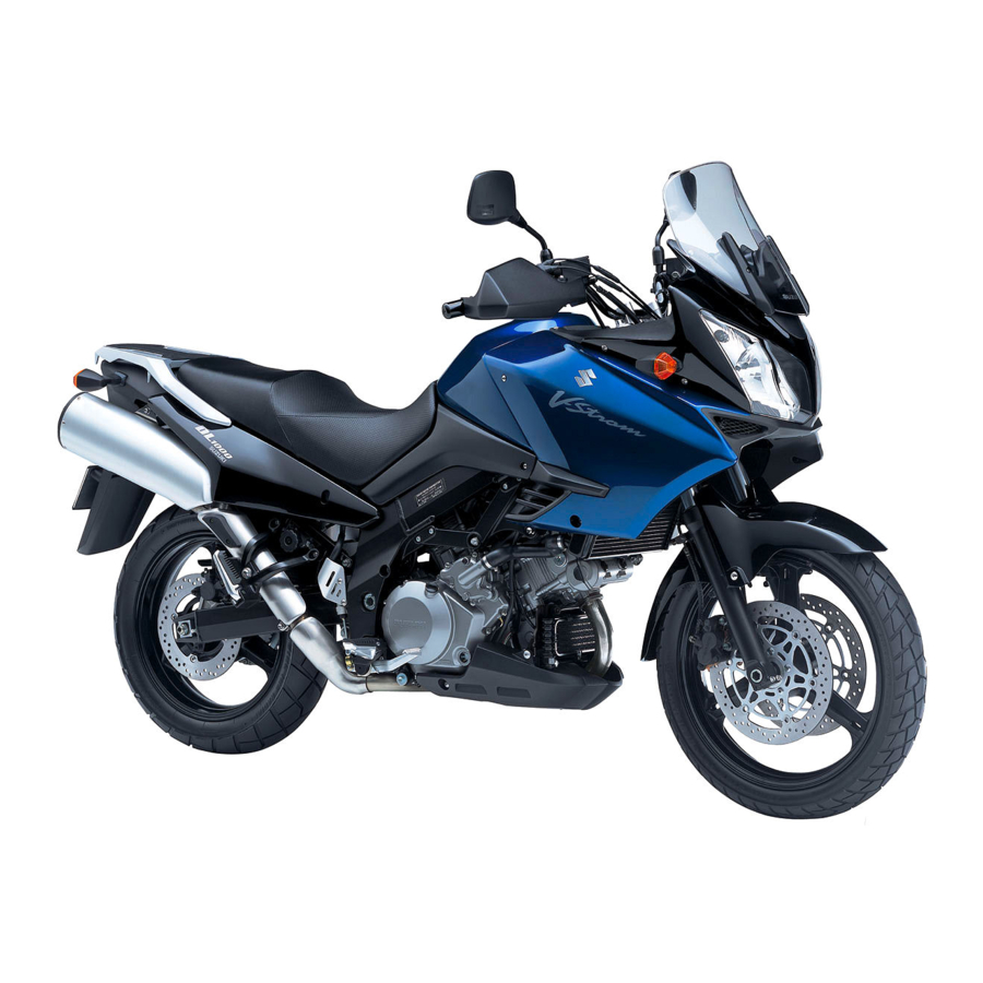
GENERAL INFORMATION SUZUKI DL1000K2 (’02-MODEL) LEFT SIDE RIGHT SIDE * Difference between photographs and actual motorcycles depends on the markets. SERIAL NUMBER LOCATION The frame serial number or V.I.N. (Vehicle Identification Number) 1 is stamped on the right side of the steering head pipe. -
Page 11: Engine Oil
Suzuki recommends the use of SUZUKI COOLANT anti-freeze/engine coolant. If this is not available, use an equivalent which is compatible with an aluminum radiator. -
Page 12: Break-Ln Procedures
GENERAL INFORMATION BREAK-lN PROCEDURES During manufacture only the best possible materials are used and all machined parts are finished to a very high standard but it is still necessary to allow the moving parts to “BREAK-IN” before subjecting the engine to maximum stresses. -
Page 13: Information Labels
GENERAL INFORMATION INFORMATION LABELS Noise label (For E-03, 24, 33) Information label (For E-03, 28, 33) ICES Canada label (For E-28) " Vacuum hose routing label (For E-33) Fuel caution label (For E-02, 24) Manual notice label (For E-03, 33) Tire pressure label &... -
Page 14: Specifications
GENERAL INFORMATION SPECIFICATIONS DIMENSIONS AND DRY MASS Overall length............2 295 mm (90.4 in) Overall width ............865 mm (34.1 in) Overall height............1 335 mm (52.6 in) Wheelbase ............1 535 mm (60.4 in) Ground clearance ..........165 mm ( 6.5 in) Seat height............ - Page 15 GENERAL INFORMATION CHASSIS Front suspension..........Inverted telescopic, coil spring, oil damped Rear suspension ..........Link type, coil spring, oil damped Steering angle ............. 40° (right & left) Caster..............26° 30’ Trail ..............111 mm (4.3 in) Turning radius ............. 2.7 m (8.86 ft) Front brake ............
-
Page 16: Country And Area Codes
1-10 GENERAL INFORMATION COUNTRY AND AREA CODES The following codes stand for the applicable country(-ies) and area(-s). CODE COUNTRY or AREA E-02 U. K. E-03 U. S. A. (Except for California) E-19 E-24 Australia E-28 Canada E-33 California (U. S. A.) -
Page 17: Periodic Maintenance
PERIODIC MAINTENANCE PERIODIC MAINTENANCE CONTENTS PERIODIC MAINTENANCE SCHEDULE ..........2- 2 PERIODIC MAINTENANCE CHART ...........2- 2 LUBRICATION POINTS ...............2- 3 MAINTENANCE AND TUNE-UP PROCEDURES .......2- 4 AIR CLEANER ................2- 4 SPARK PLUG ................2- 5 TAPPET CLEARANCE ..............2- 7 FUEL HOSE .................2-12 ENGINE OIL AND OIL FILTER ............2-12 ENGINE IDLE SPEED ..............2-14 THROTTLE CABLE PLAY ............2-14... -
Page 18: Periodic Maintenance Schedule
PERIODIC MAINTENANCE PERIODIC MAINTENANCE SCHEDULE The chart below lists the recommended intervals for all the required periodic service work necessary to keep the motorcycle operating at peak performance and economy. Mileages are expressed in terms of kilome- ters, miles and time for your convenience. NOTE: More frequent servicing may be performed on motorcycles that are used under severe conditions. -
Page 19: Lubrication Points
PERIODIC MAINTENANCE LUBRICATION POINTS Proper lubrication is important for smooth operation and long life of each working part of the motorcycle. Major lubrication points are indicated below. Clutch lever holder Side-stand pivot Footrest pivot Drive chain and spring hook Brake lever holder and throttle cables Brake pedal pivot and footrest pivot... -
Page 20: Maintenance And Tune-Up Procedures
PERIODIC MAINTENANCE MAINTENANCE AND TUNE-UP PRO- CEDURES This section describes the servicing procedures for each item of the Periodic Maintenance requirements. AIR CLEANER Inspect every 6 000 km (4 000 miles, 6 months) and replace every 18 000 km (11 000 miles, 18 months). •... -
Page 21: Spark Plug
PERIODIC MAINTENANCE NOTE: When cleaning the air cleaner element, drain water from the air cleaner by removing the drain plug. SPARK PLUG Inspect every 6 000 km (4 000 miles, 6 months) and replace every 12 000 km (7 500 miles, 12 months). NO.1 (FRONT) SPARK PLUG REMOVAL •... - Page 22 PERIODIC MAINTENANCE NO.2 (REAR) SPARK PLUG REMOVAL • Remove the seat. (!6-4) • Lift and support the fuel tank. (!4-51) • Remove the spark plug cap. • Remove the spark plug with a spark plug wrench. HEAT RANGE • Check to see the heat range of the plug. Standard Cold type CR8EK...
-
Page 23: Tappet Clearance
PERIODIC MAINTENANCE SPARK PLUG AND PLUG CAP INSTALLATION " Before using a spark plug wrench, carefully turn the spark plug by finger into the threads of the cylinder head to prevent damage the aluminum threads. • Install the spark plugs to the cylinder heads by finger tight, and then tighten them to the specified torque. - Page 24 PERIODIC MAINTENANCE • Remove the generator cover plug 1 and timing inspection plug 2. • Turn the crankshaft to set the No.1 (Front) cylinder at TDC of compression stroke. (Align the “F | T” line on the generator rotor to the index mark of valve timing inspection hole and also bring the camshafts to the position as shown in page 2-7.) •...
- Page 25 PERIODIC MAINTENANCE TAPPET CLEARANCE ADJUSTMENT The clearance is adjusted by replacing the existing tappet shim by a thicker or thinner shim. • Remove the intake or exhaust camshafts. (!3-20) • Remove the tappet and shim by fingers or magnetic hand. •...
- Page 26 2-10 PERIODIC MAINTENANCE (INTAKE SIDE)
- Page 27 PERIODIC MAINTENANCE 2-11 (EXHAUST SIDE)
-
Page 28: Fuel Hose
2-12 PERIODIC MAINTENANCE FUEL HOSE Inspect every 6 000 km (4 000 miles, 6 months). Replace every 4 years. Inspect the fuel feed hose A for damage and fuel leakage. If any defects are found, the fuel hoses must be replaced. ENGINE OIL AND OIL FILTER (ENGINE OIL) Replace initially at 1 000 km (600 miles, 1 month) and... - Page 29 Filter change: 2.9 L (3.1/2.6 US/Imp qt) Overhaul engine: 3.3 L (3.5/2.9 US/Imp qt) " ONLY USE A GENUINE SUZUKI MOTORCYCLE OIL FILTER. Other manufacturer’s oil filters may differ in thread specifications (thread diameter and pitch), fil- tering performance and durability which may lead to engine damage or oil leaks.
Need help?
Do you have a question about the DL1000 and is the answer not in the manual?
Questions and answers