Advertisement
NOTICE OF SET-UP MANUAL
SUBJECT:
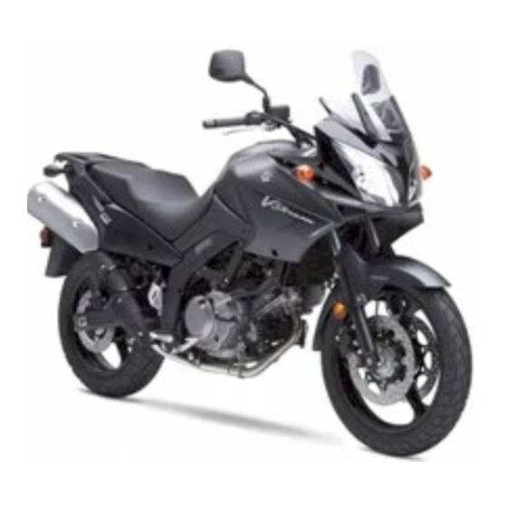
DL650AK8
APPLICABLE MODEL:
EFFECTIVE ENGINE OR FRAME NO.:
REFERENCE:
This bulletin is to inform you of set-up procedures of DL650AK8.
Please inform your dealers of this notice.
DL650AK8 Set-Up Manual will not be issued because the set-up procedures for this model remain
unchanged from DL650K4 except the differences described below.
To set-up DL650AK8, please use the DL650K4 Set-Up Manual and this Service Bulletin.
DIFFERENCE BETWEEN DL650K4 AND DL650AK8
1. LOCATION OF PARTS [Page: 2, 3, 4]
Item
Part Name
Windscreen
Screw
A
Collared spacer
Rubber cushion (with nut)
Windscreen cover
B
Tapping screw
Handlebars assembly
Clamp
Allen bolt
Burring washer
Plastic cap
C
Screw
Screw
Screw
Strap
Clutch lever cover
NOTE:
The parts shown as Item J and K in the above table are supplied for limited markets.
Use washers of Item I for mounting the license plate.
Please hand over the parts shown as Items H and M in the above table to your customer together with
motorcycle.
DL650K4 Set-Up Manual: 99505-01124-011
Q'ty
Remarks
1
4
5 × 20 mm
4
OD:14.0 ID:5.5 T:5.0
4
5 mm L:17.0
2
2
5 × 16 mm
1
2
4
8 × 30 mm
4
OD:13.0 ID:8.5
OD11.0
4
For handlebar clamp
bolt
5 × 25 mm
1
For left switch
5 × 40 mm
1
For left switch
5 × 30 mm
1
For throttle assembly
2
L:140
1
Item
Part Name
Handlebar balancer weight
Screw
Flange rubber cushion
D
Spacer
Spacer
Rubber cushion
Spacer nut
E
Rear view mirror
F
Flange bolt
G
Front wheel assembly
H
Helmet holder wire
I
Washer
J
Warning label set
K
Warning label set
Battery electrolyte
L
container
M
Owner's manual set
Holder
N
Flange bolt
T
L
OD ID
MOTORCYCLE
Jul. 27, 2007
DATE:
1
14
PAGE:
OF
Q'ty
Remarks
1
Right
1
6 × 105 mm
1
L:34.0
1
L:50.0
1
OD:16.0 ID:6.5 T:4.0
1
L:15.0
1
6 mm
2
Right and Left
10 × 25 mm for
1
front brake caliper
1
2
2
OD:13.0 ID:6.5
For
7
E-19 CC selection
For
4
E-19 CD selection
1
1
For front brake
1
master cylinder
2
6 × 22 mm
OD : Outside diameter (mm)
ID : Inside diameter (mm)
L : Length (mm)
T : Thickness (mm)
Advertisement
Table of Contents

Related Manuals for Suzuki DL650AK8


Summary of Contents for Suzuki DL650AK8
- Page 1 This bulletin is to inform you of set-up procedures of DL650AK8. Please inform your dealers of this notice. DL650AK8 Set-Up Manual will not be issued because the set-up procedures for this model remain unchanged from DL650K4 except the differences described below.
-
Page 2: Removing The Bracket
MOTORCYCLE Jul. 27, 2007 DATE: PAGE: RIGHT LEFT [Page: 5, 6 Paragraph: 1] The photographs shown indicate the parts dismounted from the motorcycle in addition to the items shown in the preceding page. A: Front brake master cylinder B: Throttle assembly C: Left switch D: Clutch cable E: Speedometer drive gearbox... -
Page 3: Front Brake Master Cylinder
MOTORCYCLE Jul. 27, 2007 DATE: PAGE: FRONT BRAKE MASTER CYLINDER [Page: 11, 12 Paragraph: 1] Install the front brake master cylinder onto the handle- bars. Align the dot mark on the handlebars with the master cylinder-to-holder fitting surface. Tighten the front brake master cylinder mounting bolts to the specified torque. -
Page 4: Front Wheel
MOTORCYCLE Jul. 27, 2007 DATE: PAGE: FRONT WHEEL [Page: 17, 18 Paragraph: 3 through Page: 21, 22 Paragraph: 1] When installing the front wheel onto the axle, special attention must be paid to the arrow of the rotational direction on the tire sidewall. FRONT FRONT When the tire is properly installed, the arrow must indi-... - Page 5 MOTORCYCLE Jul. 27, 2007 DATE: PAGE: Install the ABS sensor bracket to the front wheel hub. When install the ABS sensor bracket, be careful not to damage the oil seal lip. A: ABS sensor bracket B: Oil seal (Lip) Align the ABS sensor bracket stopper with stopper on the right fork leg.
-
Page 6: Warning Label
MOTORCYCLE Jul. 27, 2007 DATE: PAGE: RIGHT LEFT [Page: 23, 24 Paragraph: The next of 2] Pass the speed sensor lead wire and ABS sen- sor lead wire to inside of the boss of front fork. A: ABS sensor lead wire B: Speed sensor lead wire C: Boss (Fork leg) WARNING LABEL... -
Page 7: Throttle Cable
MOTORCYCLE Jul. 27, 2007 DATE: PAGE: THROTTLE CABLE [Page: 37, 38 Paragraph: 3, 4] This motorcycle has a twin throttle cable system. Cable A is for pulling cable and cable B is for return- 2.0–4.0 mm ing. Check the throttle cable play at the throttle grip. Throttle cable play: 2.0–4.0 mm If adjustment is necessary, carry out the procedure below:... -
Page 8: Rear Suspension
MOTORCYCLE Jul. 27, 2007 DATE: PAGE: REAR SUSPENSION [Page: 43, 44 Paragraph: 3] Rebound Damping Force Adjustment (For Canada) Adjust the setting of the rebound damping force to the standard position. Standard setting: 1 turn back To adjust, turn the adjuster B clockwise until it stops and then turn it counterclockwise until approximately 1 turn and the two punch marks align. - Page 9 MOTORCYCLE Jul. 27, 2007 DATE: PAGE: 2. Remove the fastener to take off the fuel tank front cover. NOTE: To remove the fastener, push in the center pin and pull out the fastener. A: Fuel tank front cover B: Fastener C: Boss 3.
- Page 10 API: American Petroleum Institute JASO: Japanese Automobile Standards Organization ENGINE OIL VISCOSITY RATING SELECTION CHART SAE Engine Oil Viscosity Suzuki recommends the use of SAE 10W-40 engine oil. 20W - 50 If SAE 10W-40 engine oil is not available, select an 15W - 40 15W - 50 alternative according to the left chart.
-
Page 11: Idle Speed Adjustment
Engine idle speed: 1 200–1 400 r/min NOTE: If the engine idle speed is not within the speci- fied range, ask your Suzuki dealer or a qualified mechanic to inspect and repair the motorcycle. 4. TIGHTENING TORQUE [Page: 51, 52, 53]... - Page 12 MOTORCYCLE Jul. 27, 2007 DATE: PAGE: 5. HARNESS ROUTING [Page: 55, 56] Clamp Clamp Handlebar switch lead wire (R) Clamp Generator lead wire Starter motor lead wire Wiring harness Wiring harness Stop lamp lead wire ABS sensor lead wire Clamp Handlebar switch lead wire (L) ISC valve coupler Clamp...
- Page 13 MOTORCYCLE Jul. 27, 2007 DATE: PAGE: Clamp Turn signal light lead wire Wiring harness Clamp Triangle mark of each spark plug cap must be brought to the exhaust side. Pass the license light lead wire in front of the seat lock cable. Reserver hose ABS brake hose Clamp...
-
Page 14: Engine And Transmission
MOTORCYCLE Jul. 27, 2007 DATE: PAGE: 6. SAFETY CHECK OUT [Page: 57, 58, 59] ELECTRICALS ITEM CHECK FOR After completion of the setting-up the motor- Light cycle all the following items should be dou- Headlight high/low beam Lighting/Adjust ble-checked to confirm that the operation and Tail/Brake light function of the motorcycle are satisfactory.
Need help?
Do you have a question about the DL650AK8 and is the answer not in the manual?
Questions and answers