Table of Contents
Advertisement
Advertisement
Table of Contents

Related Manuals for Teac AG20D


Summary of Contents for Teac AG20D
- Page 2 The warranty does not cover freight or insurance. In all cases of transit damage or lost, a claim must be filed against the carrier by the purchaser, even if shipment is arranged by TEAC. TEAC in- home service may also be available at a fee upon request.
- Page 3 *Your nearest Authorised TEAC Service Centre is listed in your Owners Manual 10. No one is authorised to assume any liability on behalf of TEAC or impose any obligation on it, in connection with the sale of any equipment other than as stated in this warranty and outlined above.
- Page 4 Dealer’s Address Postcode Please ensure that your product is packed appropriately upon return to the service centre. If you have any other queries regarding service or warranty please contact the TEAC Customer Care Centre below: service@teac.com.au www.teac.com.au 1800 656 700...
-
Page 5: Table Of Contents
CONTENTS SAFETY INFORMATION……………………………………………………………………………………………. 1 IMPORTANT SAFETY INSTRUCTIONS …………………………….…………………………………..………. 2 BEFORE USE ………………………………………………………………………………………………..………. 4 CONNECTION ……………………………………………………………………………………………..………… 5 REMOTE CONTROL UNIT ………………………………………………………………………………..……….. 10 FRONT PANEL INFORMATION ……………………………………………………………………….…………... 11 REAR PANEL INFORMATION ………………………………………………………………………….………….. 12 REMOTE CONTROL INFORMATION ………………………………………………………………….…………. 13 BASIC OPERATION ………………………………………………………………………………………………… 15 SPEAKER CONFIGURATION, DELAY TIME &... -
Page 6: Safety Information
SAFETY INFORMATION Caution: To reduce the risk of electric shock, do not remove Cover (or back) No user-serviceable parts inside. Refer servicing to qualified service personnel. Do not expose this appliance to rain or moisture This lightning flash with arrowhead symbol, within an equilateral triangle is intended to alert the user to the presence of uninstalled “dangerous voltage”... -
Page 7: Important Safety Instructions
IMPORTANT SAFETY INSTRUCTIONS CAUTION: READ THIS BEFORE OPERATING YOUR UNIT. 1. READ AND FOLLOW INSTRUCTIONS: All the safety and operation instructions should be read before the product is operated. Follow all operation instructions within this manual. 2. RETAIN THESE INSTRUCTIONS: The safety and operation instructions should be retained for future reference. - Page 8 IMPORTANT SAFETY INSTRUCTIONS If liquid has been spilled, or objects have fallen into the product. If the product has been exposed to rain or water. If the product does not operate normally by following the operation instructions, adjusting only those controls that are covered by the operation instructions.
-
Page 9: Before Use
BEFORE USE Read this before operation Before Connection 1. Choose the installation location of your unit Caution carefully. Avoid placing it in direct sunlight or - Disconnect all equipment from the power source close to a source of heat. Also avoid locations before making any connections. -
Page 10: Connection
CONNECTION Jagged metal FM INDOOR ANTENNA Insert into slit. If you live reasonably close to a transmitter and want to use the provided lead-type FM antenna, you will have to connect it direct to the “FM 75” socket. Jagged metal Fit the metal sleeve of the lead-type antenna over AM INDOOR LOOP ANTENNA the core (center) conductor of the (FM 75) socket,... - Page 11 CONNECTION Speaker layout example when using surround mode 1. TV or Screen 2. Front Left Speaker 3. Subwoofer 4. Center Speaker 5. Front Right Speaker 6. Surround Left Speaker 7. Surround Right Speaker 8. Listening Position Standard speaker setup for surround sound ●...
- Page 12 CONNECTION SPEAKER CONNECTION SURROUND BACK HDMI S-VIDEO AV 1 MONITOR MODEL NO: AG 20D POWER SOURCE: 220V-240V~50Hz AV2 IN AV1 IN DVD IN POWER CONSUMPTION: 300W N53 3 RS232C VIDEO LOOP MONITOR AV 1 AV 2 RISK OF ELECTRIC SHOCK DO NOT OPEN SE RIA L N O.
- Page 13 CONNECTION DVD, VCD S-VIDEO OUT VIDEO OUT HDMI OUT HDMI S-VIDEO VIDEO 1 MONITOR AV2 IN AV1 IN DVD IN RS232C VIDEO ANTENNA MONITOR VIDEO 1 VIDEO 2 DVD IN LOOP OPTICAL COAXIAL VIDEO 1 VIDEO 2 TAPE TAPE VIDEO 1 VIDEO 2 DIGITAL INPUT COAX OUT...
- Page 14 CONNECTION Audio connections: CD, TAPE jacks Some video components are equipped with special Connect the component with RCA to RCA cords. digital audio outputs (e.g. DVD players). If your video Make sure to connect: component is equipped with a digital audio output, it is recommended that you connect to your unit using White plug to white jack (L: left) a digital cable.
-
Page 15: Remote Control Unit
REMOTE CONTROL UNIT BATTERY INSTALLATION By using the provided remote control unit, this unit can be controlled from your listening position. To use the remote control unit, point it at the REMOTE SENSOR window of this unit. Notes: - Even if the remote control unit is operated within the effective range, remote control operation may be impossible if there are any obstacles between the unit and the remote control. -
Page 16: Front Panel Information
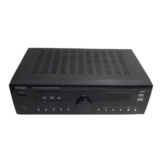
FRONT PANEL INFORMATION AG20D 5.1 CHANNEL HOME THEATRE RECEIVER POWER VOLUME STEREO STATION R E S E T TUNER DTS/DOLBY DIGITAL SURROUND PHONES /BAND DIGITAL MODE ON/OFF TAPE VIDEO 2 VIDEO 1 1. POWER Turns the unit on/off. 12. AUX Press this button to select AUX. -
Page 17: Rear Panel Information
REAR PANEL INFORMATION HDMI HDMI S-VIDEO AV 1 MONITOR MODE L NO: AG20D POWER S OU RCE: 220V-240V~ 50H z AV2 IN AV1 IN DVD IN POWER CONS UMPT ION: 300W N5 3 3 RS232C VIDEO LOOP MONITOR AV 1... -
Page 18: Remote Control Information
REMOTE CONTROL INFORMATION POWER VIDEO 1 VIDEO 2 TUNER TAPE MEMORY ST/MONO MANUAL BAND TUNING PRESET + MUTE PRESET SUBWOOFER DIMMER SELECT ON/OFF BASS LFE TRIM TREBLE INPUT MODE BASS TEST DELAY TIME MODE TONE SURROUND MODE DTS/DOLBY DIGITAL AG20D... - Page 19 REMOTE CONTROL INFORMATION 1. Display Press this button to display the state of input source. And when listening to the FM broadcasting with RDS, press this button to show PS, PTY, RT and RT. 2. Input Source Choose the input as your desire, you can chosse DVD VIDEO1 VIDEO2 TUNER AUX and TAPE 3.
-
Page 20: Basic Operation 1
BASIC OPERATION BASIC OPERATION 1 1. Press the POWER button to put this unit into Standby Mode. 2. Press one of the source buttons to activate the unit. 3. Select the desired source by pressing DVD, VIDEO 1, VIDEO 2, TUNER, AUX or TAPE. If you have selected DVD, VIDEO 1, VIDEO 2 (not TUNER, AUX or TAPE), press INPUT MODE, SURROUND MODE, DTS/DOLBY DIGITAL, STEREO, DOLBY PROLOGIC II or DIGITAL IN in accordance with the type of signal you are receiving and the sound output you require (for example, Dolby... - Page 21 BASIC OPERATION PLAYING VIDEO SOURCES 1. Select DVD, VIDEO1, VIDEO 2 by pressing the corresponding button. 2. Play the sound source corresponding to the source selected (for example, if you have selected DVD, press PLAY on your DVD player). 3. The picture from the video source will be transmitted to the TV and the sound from the video source will be heard from the speakers.
-
Page 22: Speaker Configuration, Delay Time & Dynamic Range Control
BASS TEST DELAY TIME MOD E TONE MANUAL BAND SURROUND TUNING MOD E DTS/DOLBY DIGITAL PRESET + DYNAMIC MUTE PRESET AG20D SUBWOOFER DIMMER SELECT ON/OFF BASS LFE TRIM TREBLE INPUT MODE BASS TEST DELAY TIME MODE TONE DELAY DRC=0/4 No Compression... -
Page 23: Test Tone, Lfe Trimmer & Channel Select
The test tone is emitted from each speaker each time BASS TEST DELAY TIME MODE TONE SURROUN D you press “TEST TONE”. MODE DTS/DOLBY DIG ITAL POWER AG20D VIDEO 2 VIDEO 1 TUNER TAPE MEMORY ST/MONO CHANNEL SELECT MANUAL BAND Balancing volume between speakers in 5.1 TUNING channel mode when using the 5.1 analogue... -
Page 24: Available Surround Mode
AVAILABLE SURROUND MODE SURROUND MODE DOLBY DIGITAL MODE The surround modes create a “live” atmosphere such as that experienced in movie theaters, discos, stadiums and concert halls. Select the appropriate surround mode according to the program source. (Note: Surround speakers needed DTS/DOLBY DIGITAL Dolby Pro Logic II surround modes to function). -
Page 25: Troubleshooting
TROUBLESHOOTING To determine a problem with your AV Receiver, always check the most obvious possible causes first. If a problem still exists after having checked the possible causes below, consult your nearest dealer. Problem Probable Cause Suggestion Amplifier When listening to the music in Incorrect speaker connections. -
Page 26: Specifications
SPECIFICATIONS AUDIO SECTION Rated Power Output FRONT 50W + 50W CENTER REAR 50W + 50W Output Terminals FRONT 6 - 8 ohms CENTER 6 - 8 ohms REAR 6 - 8 ohms Total Harmonic Distortion Less than 0.05% at1/2 rated power output LINE INPUT Input Sensitivity/Impedance 150mV/47kΩ... -
Page 27: Complete Service Agent List
Service Providers in Australia please contact one of the following service providers in your area if you require service for your product. Name Address Service area Phone Associated Electronics 7 Molonglo Mall CANBERRA 2609 (02)62 80 4698 (02)62 80 5437 Name Address Service area... - Page 28 Name Address Service area Phone McMahon Electrical Traders 23 Mabel Street ATHERTON 4883 (07)40 91 1788 (07)40 91 1741 Beerwah Electronics Peachester Road BEERWAH 4519 (07)54 94 0466 (07)54 94 0416 BTronics Shop 1/176 Callide Street BILOELA 4715 (07)49 92 6566 (07)49 92 5266 Bremer Television Service 36 Station Road...
- Page 29 6312 (08)98 81 2148 (08)98 81 3129 Proton 21A Charles Street NORTHAM 6401 (08)96 22 3168 (08)96 22 3168 TEAC Perth Service Centre 273 Great Eastern Highway PERTH 6104 (08)94 79 6499 (08)94 79 6544 Charles Hunt Electronics 25 Brodie Court...
- Page 30 TEAC CUSTOMER CARE CENTRE (TCCC) Free call: 1800 656 700 Between Monday to Friday – EST 9AM to 5PM...
Need help?
Do you have a question about the AG20D and is the answer not in the manual?
Questions and answers