
Summary of Contents for JVL Echo
- Page 1 To Purchase This Item, Visit BMI Gaming | www.bmigaming.com | (800) 746-2255 | +1.561.391.7200...
-
Page 2: Table Of Contents
13. Upper Glass Lights PCB Replacement......................18 14. Amplifier PCB Replacement..........................19 15. Power Supply Replacement..........................20 16. Main Fan Replacement............................21 17. Service Lights PCB Replacement........................22 18. Wi-Fi Adapter Replacement..........................23 19. Modem Replacement............................24 Appendix A..................................26 Appendix B..................................60 Copyright © 2011 JVL Labs All Rights Reserved... -
Page 3: Safety Information
If you require any assistance, please contact Technical Support at 1-800-296-6657. The information in this manual is subject to change without notice. JVL and JVL logo are registered trademarks of JVL Labs. Product names mentioned herein are for identification purposes only and may be trademarks and/or registered trade- marks of their respective companies. -
Page 4: General Description
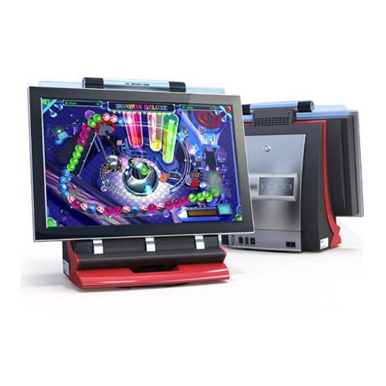
To Purchase This Item, Visit BMI Gaming | www.bmigaming.com | (800) 746-2255 | +1.561.391.7200 General description General DescrIpTIon ECHO is a countertop with following features: • 22 inch LCD screen that delivers a true HD entertainment experience • LCD screen featuring red accents and a glossy piano finish •... - Page 5 To Purchase This Item, Visit BMI Gaming | www.bmigaming.com | (800) 746-2255 | +1.561.391.7200 General description Operator Information: After opening back door, you will have access to the Setup Button. Set Up Button Back Door Sensor Copyright © 2011 JVL Labs All Rights Reserved...
-
Page 6: Flash Memory Card Replacement
7. Press onto the existing SD Memory card to eject it from its socket. Replace it with the new one (see Fig. 7 on page 31 for details). 8. Reassemble the countertop by following the previous steps in reverse order. NOTE: For part numbers see Appendix B Copyright © 2011 JVL Labs All Rights Reserved... -
Page 7: Game Box Replacement
CPU Box (see Fig. 11 on page 33 for details). 10. Reassemble the countertop by following the previous steps in reverse order. NOTE: For part numbers see Appendix B Copyright © 2011 JVL Labs All Rights Reserved... -
Page 8: Game Box Fans Replacement
CPU and Mobile Graphics chip (see Fig. 14 on page 35 for details). 12. Reassemble the countertop by following the previous steps in reverse order. NOTE: For part numbers see Appendix B Copyright © 2011 JVL Labs All Rights Reserved... -
Page 9: Coin Mechanism Replacement
(see Fig. 16 on page 36 for details). 6. Replace the old Coin Acceptor with the new one. 7. Reassemble the countertop by following the previous steps in reverse order. NOTE: For part numbers see Appendix B Copyright © 2011 JVL Labs All Rights Reserved... -
Page 10: Coin Sensor Replacement
7. Unscrew two machine screws #8-32 x 1/4”. Remove the Coin Acceptor Bracket from the ma- chine (see Fig. 18 on page 38 for details). 8. Unscrew two machine screws #4-40 x 1/4” and replace the old JVL Sensor PCB with the new one (see Fig. 44 on page 52 for details). -
Page 11: Monitor Unit Replacement
9. Remove the Monitor assembly by lifting upwards. Replace with the new one. 10. Reassemble the countertop by following the previous steps in reverse order. NOTE: For part numbers see Appendix B Copyright © 2011 JVL Labs All Rights Reserved... -
Page 12: Bill Acceptor Replacement
Bill Acceptor connector (see Fig. 28 on page 43 for details). 16. Disconnect the BA Harness connector from the Bill Acceptor (depending on the type of Bill Acceptor). 17. Set aside the Bill Acceptor with Bill Acceptor bracket. Copyright © 2011 JVL Labs All Rights Reserved... - Page 13 Bill Acceptor with the new one (see Fig. 29 on page 44 for details). 19. Reassemble the countertop by following the previous steps in reverse order. NOTE: For part numbers see Appendix B Copyright © 2011 JVL Labs All Rights Reserved...
-
Page 14: I/O Board Replacement
8. Carefully remove the Dallas Key and place it into the new I/O Board (see Fig. 32 on page 45 for details). 9. Reassemble the countertop by following the previous steps in reverse order. NOTE: For part numbers see Appendix B Copyright © 2011 JVL Labs All Rights Reserved... -
Page 15: Counter Replacement
8. Unscrew one Machine Screw M3 x 6 and replace the old counter with the new one (see Fig. 33 on page 46 for details). 9. Reassemble the countertop by following the previous steps in reverse order. NOTE: For part numbers see Appendix B Copyright © 2011 JVL Labs All Rights Reserved... -
Page 16: Power Pad Assembly Replacement
Board (see Fig. 36 on page 48 for details). 7. Replace the old Power Pad Assembly with the new one. 8. Reassemble the countertop by following the previous steps in reverse order. NOTE: For part numbers see Appendix B Copyright © 2011 JVL Labs All Rights Reserved... -
Page 17: Upper Glass Replacement
5. Unscrew four Tapping Screws #8 x 3/4” (see Fig. 37 on page 48 for details). 6. Replace the Upper Glass with the new one. 7. Reassemble the countertop by following the previous steps in reverse order. NOTE: For part numbers see Appendix B Copyright © 2011 JVL Labs All Rights Reserved... -
Page 18: Upper Glass Lights Pcb Replacement
PCB from behind (see Fig. 39 on page 49 for details). 8. Reassemble the countertop by following the previous steps in reverse order. NOTE: For part numbers see Appendix B Copyright © 2011 JVL Labs All Rights Reserved... -
Page 19: Amplifier Pcb Replacement
8. Unscrew two Machine Screws #4-40 x 3/16” (see Fig. 42 on page 51 for details) and replace the old Amplifier PCB with the new one. 9. Reassemble the countertop by following the previous steps in reverse order. NOTE: For part numbers see Appendix B Copyright © 2011 JVL Labs All Rights Reserved... -
Page 20: Power Supply Replacement
7. Unscrew 4 Machine Screws #6-32 x 3/8” (see Fig. 46 on page 53 for details) 8. Replace the old Power Supply with the new one. 9. Reassemble the countertop by following the previous steps in reverse order. NOTE: For part numbers see Appendix B Copyright © 2011 JVL Labs All Rights Reserved... -
Page 21: Main Fan Replacement
12. Unscrew two Machine Screws #4–40 x 3/8” and replace the old Fan with the new one (see Fig. 50 on page 55 for details). 13. Reassemble the countertop by following the previous steps in reverse order. NOTE: For part numbers see Appendix B Copyright © 2011 JVL Labs All Rights Reserved... -
Page 22: Service Lights Pcb Replacement
5. Unscrew two Machine Screws #4–40 x 3/16” and replace the old PCB with the new one (see Fig. 52 on page 56 for details). 6. Reassemble the countertop by following the previous steps in reverse order. NOTE: For part numbers see Appendix B Copyright © 2011 JVL Labs All Rights Reserved... -
Page 23: Wi-Fi Adapter Replacement
4. Carefully move to your right side Wi-Fi adapter. Disconnect it and replace with the new one (see Fig. 53 on page 57 for details). 5. Reassemble the countertop by following the previous steps in reverse order. NOTE: For part numbers see Appendix B Copyright © 2011 JVL Labs All Rights Reserved... -
Page 24: Modem Replacement
9. Install the new modem. Use Velcro fastener to mount it into the machine (See Fig. 57 on page 58 for details). 10. Reassemble the countertop by following the previous steps in reverse order. NOTE: For part numbers see Appendix B Copyright © 2011 JVL Labs All Rights Reserved... - Page 25 To Purchase This Item, Visit BMI Gaming | www.bmigaming.com | (800) 746-2255 | +1.561.391.7200 appendix a (Assembly Drawings) ECHO Copyright © 2011 JVL Labs All Rights Reserved...
-
Page 26: Appendix A
To Purchase This Item, Visit BMI Gaming | www.bmigaming.com | (800) 746-2255 | +1.561.391.7200 Appendix A CT09-106 Back Door Assembly Fig. 1 Copyright © 2011 JVL Labs All Rights Reserved... - Page 27 To Purchase This Item, Visit BMI Gaming | www.bmigaming.com | (800) 746-2255 | +1.561.391.7200 Appendix A Fig. 2 Copyright © 2011 JVL Labs All Rights Reserved...
- Page 28 To Purchase This Item, Visit BMI Gaming | www.bmigaming.com | (800) 746-2255 | +1.561.391.7200 Appendix A Machine Screw #8-32 x 1/4” Philips Head Machine Screw #8-32 x 3/8” Philips Head Fig. 3 Copyright © 2011 JVL Labs All Rights Reserved...
- Page 29 To Purchase This Item, Visit BMI Gaming | www.bmigaming.com | (800) 746-2255 | +1.561.391.7200 Appendix A CT09-121 Monitor Door Stopper Cable CT09-101 Monitor Assy Fig. 4 Copyright © 2011 JVL Labs All Rights Reserved...
- Page 30 To Purchase This Item, Visit BMI Gaming | www.bmigaming.com | (800) 746-2255 | +1.561.391.7200 Appendix A Depress both latches Depress both latches to remove the Cover to remove the Cover Fig. 5 CT09-122 CPU Hex Nut #8-32 GAMEBOARD ASSEMBLY Fig. 6 Copyright © 2011 JVL Labs All Rights Reserved...
- Page 31 To Purchase This Item, Visit BMI Gaming | www.bmigaming.com | (800) 746-2255 | +1.561.391.7200 Appendix A SD Memory Card Fig. 7 1, 2 3, 4 Fig. 8 Copyright © 2011 JVL Labs All Rights Reserved...
- Page 32 To Purchase This Item, Visit BMI Gaming | www.bmigaming.com | (800) 746-2255 | +1.561.391.7200 Appendix A Fig. 9 DC Harness Game Board Power Connector Fig. 10 Copyright © 2011 JVL Labs All Rights Reserved...
- Page 33 To Purchase This Item, Visit BMI Gaming | www.bmigaming.com | (800) 746-2255 | +1.561.391.7200 Appendix A SD Memory Card Game Box Assembly (CT09-122) Fig. 11 Machine Screw #6-32 x 1/4” Philips Head Game Box Fig. 12 Copyright © 2011 JVL Labs All Rights Reserved...
- Page 34 To Purchase This Item, Visit BMI Gaming | www.bmigaming.com | (800) 746-2255 | +1.561.391.7200 Appendix A Fan cables Fig. 13 Copyright © 2011 JVL Labs All Rights Reserved...
- Page 35 To Purchase This Item, Visit BMI Gaming | www.bmigaming.com | (800) 746-2255 | +1.561.391.7200 Appendix A Machine Screw #4-40 x 16”, Philips Head, 4 Places Air Flow Direction Inner Fans: DC12V-50 x 50 x 15 mm P/N: KDE1205PHV2 MS.AF.GN Fig. 14 Copyright © 2011 JVL Labs All Rights Reserved...
- Page 36 To Purchase This Item, Visit BMI Gaming | www.bmigaming.com | (800) 746-2255 | +1.561.391.7200 Appendix A Coin Accptor Lock Fig. 15 Fig. 16 Copyright © 2011 JVL Labs All Rights Reserved...
- Page 37 To Purchase This Item, Visit BMI Gaming | www.bmigaming.com | (800) 746-2255 | +1.561.391.7200 Appendix A Coin Sensor connector Fig. 17 Copyright © 2011 JVL Labs All Rights Reserved...
- Page 38 To Purchase This Item, Visit BMI Gaming | www.bmigaming.com | (800) 746-2255 | +1.561.391.7200 Appendix A CT09-112 Coin Acceptor Bracket Machine Screw #8-32 x 1/4”, Philips Head, 2 Places Fig. 18 Machine Screw #4-40 x 1/4”, Philips Head, 2 Places Coin Sensor Fig. 19 Copyright © 2011 JVL Labs All Rights Reserved...
- Page 39 Touch Screen cable LVDS cable Fig. 20 NOTE: Touch screen USB cable is labeled HNS-CT09-716 and can be connected to any USB slot on the Game Box. Hex Lock Nut #8-32 Clamp Fig. 21 Copyright © 2011 JVL Labs All Rights Reserved...
- Page 40 Door Stopper Cable Machine Screw #8-32 x 3/8”, Philips Head, 2 Places Fig. 22 Upper Twetters Connectors CPU Box Audio Cable Connector Subwoofer Cable Connector Power Cable Connector Mid-Range Speakers Connector Fig. 23 Copyright © 2011 JVL Labs All Rights Reserved...
- Page 41 To Purchase This Item, Visit BMI Gaming | www.bmigaming.com | (800) 746-2255 | +1.561.391.7200 Appendix A Cash Harness Ground Hex Lock Num #8-32 Fig. 22 Fig. 24 Bill Cassette Fig. 25 Copyright © 2011 JVL Labs All Rights Reserved...
- Page 42 To Purchase This Item, Visit BMI Gaming | www.bmigaming.com | (800) 746-2255 | +1.561.391.7200 Appendix A CT09-214 BV Cover Fig. 26 Bill Acceptor Assembly P/N: CT09-111 Machine Screw #8-32 x 3/8”, Philips Head Fig. 27 Copyright © 2011 JVL Labs All Rights Reserved...
- Page 43 Fig. 28 NOTE: 1) Amplifier Shield not shown in this picture. 2) Position of Bill Acceptor Connector may vary depending on the model and type (Mars Bill Ac- ceptor shown in the picture). Copyright © 2011 JVL Labs All Rights Reserved...
- Page 44 To Purchase This Item, Visit BMI Gaming | www.bmigaming.com | (800) 746-2255 | +1.561.391.7200 Appendix A CT09-313 Bill Acceptor Bracket Bill Acceptor Hex Lock Nut #8-32 4 Places Fig. 29 Fig. 30 Copyright © 2011 JVL Labs All Rights Reserved...
- Page 45 To Purchase This Item, Visit BMI Gaming | www.bmigaming.com | (800) 746-2255 | +1.561.391.7200 Appendix A IO Board P/N: CT09-410 Machine Screw #4-40 x 3/16” Philips Head, 2 Places Fig. 31 Security Key Fig. 32 Copyright © 2011 JVL Labs All Rights Reserved...
- Page 46 To Purchase This Item, Visit BMI Gaming | www.bmigaming.com | (800) 746-2255 | +1.561.391.7200 Appendix A Machine Screw M3 x 6 LNG, Pan Head Philips Counter 42-0750-07 Fig. 33 Copyright © 2011 JVL Labs All Rights Reserved...
- Page 47 To Purchase This Item, Visit BMI Gaming | www.bmigaming.com | (800) 746-2255 | +1.561.391.7200 Appendix A Power Pad Assembly (CT09-120) Tapping Screw #8 x 3/8” Philips Head, 6 Places Fig. 34 Power Pad USB cable Fig. 35 Copyright © 2011 JVL Labs All Rights Reserved...
- Page 48 To Purchase This Item, Visit BMI Gaming | www.bmigaming.com | (800) 746-2255 | +1.561.391.7200 Appendix A RFID board cable Fig. 36 Tapping Screw #8 x 3/4” Upper Glass Philips Head, 4 Places Fig. 37 Copyright © 2011 JVL Labs All Rights Reserved...
- Page 49 To Purchase This Item, Visit BMI Gaming | www.bmigaming.com | (800) 746-2255 | +1.561.391.7200 Appendix A Upper Lights PCB connector Fig. 38 Upper Glass Light PCB P/N: CT09-406 Fig. 39 Copyright © 2011 JVL Labs All Rights Reserved...
- Page 50 Appendix A Amplifier Shield P/N: CT09-325 Hex Nut #8-32 Fig. 40 Upper Tweeters Cable Connector CPU Box Audio Cable Connector Power Cable Connector Mid-range Speakers Cable Connector Subwoofer Cable Connector Fig. 41 Copyright © 2011 JVL Labs All Rights Reserved...
- Page 51 Amplifier PCB P/N: CT09-409 Amplifier Shield P/N: CT09-328 Machine Screw #4-40 x 3/16” Philips Head, 2 Places Fig. 42 CT09-105 Coin Out Assy Machine Screw #8-32 x 3/8” Philips Head, 3 Places Fig. 43 Copyright © 2011 JVL Labs All Rights Reserved...
- Page 52 To Purchase This Item, Visit BMI Gaming | www.bmigaming.com | (800) 746-2255 | +1.561.391.7200 Appendix A CT09-110 Power Supply Assmbly Machine Screw #8-32 x 1/4” Philips Head, 3 Places Fig. 44 Copyright © 2011 JVL Labs All Rights Reserved...
- Page 53 To Purchase This Item, Visit BMI Gaming | www.bmigaming.com | (800) 746-2255 | +1.561.391.7200 Appendix A AC Harness (CT09-701) DC Harness (CT09-702) Fig. 45 Power Supply Machine Screw #6-32 x 3/8” Philips Head, 4 Places Fig. 46 Copyright © 2011 JVL Labs All Rights Reserved...
- Page 54 #8-32 x 1” 1/4” LNG., Pan Head Philips 2x Machine Screw #8-32 x 3/8” LNG., Pan Head Philips Fig. 47 2x Flat Washer #8 2x Machine Screw #8-32 x 1/4” LNG., Phill Pan Screw Fig. 48 Copyright © 2011 JVL Labs All Rights Reserved...
- Page 55 To Purchase This Item, Visit BMI Gaming | www.bmigaming.com | (800) 746-2255 | +1.561.391.7200 Appendix A 2x Machine Screw #8-32 x 1/4” LNG, Pan Head Phillips Fig. 49 Machine Screw #4-40 x 3/8” Phillips Head, 2 Places Fig. 50 Copyright © 2011 JVL Labs All Rights Reserved...
- Page 56 To Purchase This Item, Visit BMI Gaming | www.bmigaming.com | (800) 746-2255 | +1.561.391.7200 Appendix A Service Light cable connector Fig. 51 Service Light PCB 2x Machine Screw #4-40 3/16” LNG. Pan Head Philips Fig. 52 Copyright © 2011 JVL Labs All Rights Reserved...
- Page 57 NOTE: Velcro fastener helps to mount the Wi-Fi adapter in the right place as shown in the picture. Fig. 54 Fig. 55 NOTE: Velcro fastener helps to mount the modem in the right place as shown in the picture (See Fig. 55). Copyright © 2011 JVL Labs All Rights Reserved...
- Page 58 To Purchase This Item, Visit BMI Gaming | www.bmigaming.com | (800) 746-2255 | +1.561.391.7200 Appendix A Fig. 56 Fig. 57 Copyright © 2011 JVL Labs All Rights Reserved...
- Page 59 To Purchase This Item, Visit BMI Gaming | www.bmigaming.com | (800) 746-2255 | +1.561.391.7200 appendix b (Parts Breakdown) ECHO Copyright © 2011 JVL Labs All Rights Reserved...
-
Page 60: Appendix B
Fig. A-1 CT09-501 Upper Glass CT09-255 Inner Devices Cover CT09-409 Amplifier PCB CT09-328 Amplifier Shield CT09-214 Bill Acceptor Cover Different versions depending on Bill Acceptor type CT09-111 Bill Acceptor Assembly Fig. A-2 Copyright © 2011 JVL Labs All Rights Reserved... - Page 61 CT09-122 CPU Box Assembly Fig. A-3 CT09-105 Coin Out CT09-112 Coin Acceptor Tray Assembly Bracket Assembly CT09-401 Coin Sensor PCB Coin Acceptor CT09-303 U-Bolt Bracket CT09-123 Rear Panel CT09-403 ESD PCB Assembly Fig. A-4 Copyright © 2011 JVL Labs All Rights Reserved...
- Page 62 CT09-215 Left Side Cover CT09-228 Upper Right Cover CT09-103 Upper Unit Assembly CT09-216 Right Side Cover CT09-102 Front Panel Assembly Fig. A-5 CT09-234 Fan Cover Main fan Counter CT09-110 Power Supply Assembly Fig. A-6 Copyright © 2011 JVL Labs All Rights Reserved...
- Page 63 CT09-231 Coin In Cover CT09-208 Back Casing CT09-230 Coin In Base CT09-104 Subwoofer Unit Assembly CT09-302 Chassis CT09-301 Base CT09-202 Turntable Disc Fig. A-7 CT09-211 Front Panel Cover CT09-210 Front Panel Column Fig. A-8 Copyright © 2011 JVL Labs All Rights Reserved...
- Page 64 CT09-248 Joystick Button Bottom CT09-237 Power Pad Pedestal CT09-412 Joystick PCB CT09-235 Power Pad Panel CT09-241 Right Button CT09-240 Left Button CT09-411 Button Board CT09-411 Button Board CT09-236 Power Pad Frame Fig. A-9 Copyright © 2011 JVL Labs All Rights Reserved...
Need help?
Do you have a question about the Echo and is the answer not in the manual?
Questions and answers
Have a JVL Echo HD Touchscreen. Today, my wife's favorite game quit working. It either freezes or reboots the machine. Seeing codes in the Event Log, but not getting Google search hits. Other games are working fine. Any help is appreciated
The JVL Echo HD Touchscreen could freeze or reboot while playing a specific game due to several potential causes:
1. Power Supply Issues: If the machine is not connected to the correct voltage (115/230V 60/50Hz AC), it may cause instability or reboots.
2. Damaged Supply Cord: A damaged power cord can lead to intermittent power loss, causing the system to freeze or reboot.
3. Software or Game Glitch: A specific game may have a bug or compatibility issue that causes the system to crash.
4. Overheating: Poor ventilation or internal dust buildup could lead to overheating, triggering reboots.
5. Storage Problems: If the high capacity SD card used for storage is corrupted or nearly full, it may affect game performance.
6. Hardware Faults: Issues with internal components like the tri-band acoustic system, Wi-Fi/USB modules, or coin/bill mechanisms may interfere with operation.
A service technician should check the system, including power supply, software, and hardware, to identify the exact cause.
This answer is automatically generated