Table of Contents
Advertisement
Quick Links
VEECT212F..
Model
• USERS OPERATING INSTRUCTIONS
• INSTALLATION ADVICE
IMPORTANT - PLEASE READ AND FOLLOW
Before beginning, please read these instructions completely and carefully.
Do not remove permanently affixed labels, warnings, or plates from the product. This
may void the warranty.
Please observe all local and national codes and ordinances.
Please ensure that this product is properly grounded.
The installer should leave these instructions with the consumer who should retain
for local inspector's use and for future reference.
The electrical connection should always be accessible
Electrical installation must be in accordance with the National Electrical Code,
ANIS/NFPA70 - latest edition and/or local codes.
IN CANADA: Electrical installation must be in accordance with the current CSA C22.1
Canadian Electrical Codes Part 1 and/or local codes.
B U I L T - I N
C E R A M I C
C O O K T O P
Advertisement
Table of Contents

Subscribe to Our Youtube Channel
Related Manuals for Verona VEECT212F Series


Summary of Contents for Verona VEECT212F Series
- Page 1 B U I L T - I N C E R A M I C C O O K T O P VEECT212F.. Model • USERS OPERATING INSTRUCTIONS • INSTALLATION ADVICE IMPORTANT - PLEASE READ AND FOLLOW Before beginning, please read these instructions completely and carefully.
- Page 2 Dear Customer, Thank you for having purchased and given your preference to our product. The safety precautions and recommendations reported below are for your own safety and that of others. They will also provide a means by which to make full use of the features offered by your appliance. Please preserve this booklet carefully.
-
Page 3: Important Precautions And Recommendations
USER INSTRUCTIONS IMPORTANT PRECAUTIONS AND RECOMMENDATIONS After having unpacked the appliance, check to ensure that it is not damaged. If you have any doubts, do not use it and consult your supplier or a professionally qualified technician. Packing elements (i.e. plastic bags, polystyrene foam, nails, packing straps, etc.) should not be left around within easy reach of children, as these may cause serious injuries. -
Page 4: Control Panel Description
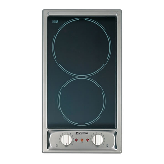
features SCHOTT Fig. 1.1 VITROCERAMIC HOB (Fig. 1.1) Electrical insulation Class I COOKING POINTS 1. Zone Ø 145 - 1200 W 2. Zone Ø 180 - 1700 W CONTROL PANEL DESCRIPTION 3. Rear zone control knob 4. Front zone control knob 5. -
Page 5: Using The Vitroceramic Hob
using the vitroceramic hob VITROCERAMIC HOB The main characteristic of this pyroceram cooker top is that it permits rapid vertical trans- mission of the heat from the heating elements below to the saucepans on top. The heat does not spread horizontally, however, and therefore the glass stays cold only a few centimetres from the hob. - Page 6 HINTS FOR SAFE USE OF THE HOBS – Before switching on, check which knob controls the required hob. You are advised to place the saucepan on the hob before switching on and to take it off after switch- ing off. –...
-
Page 7: Cleaning And Maintenance
cleaning and maintenance GENERAL RECOMANDATION Do not use steam jet cleaners because the humidity could Before you begin cleaning you must ensure that the hob is switched off. infiltrate into the appliance making It is advisable to clean when the appliance is cold and especially when cleaning it dangerous. -
Page 8: Installation Instructions
INSTALLATION INSTRUCTIONS WARNING! THIS APPLIANCE HAS TO BE INSTALLED BY A QUALIFIED INSTALLER. Improper installation, adjustment, alteration, services, or maintenance can cause injury or property damage. Consult a qualified installer, service agent, or the gas supplier. GENERAL INFORMATION 1. Installation must conform with local codes. 2. -
Page 9: Cooktop Dimensions
installation to the cabinet COOKTOP DIMENSIONS 11” 21/64 (288 mm) (CUT-OUT) min 3” SCHOTT 10” 5/8 (76.2 mm) (270 mm) form cut-out BOX DIMENSIONS Fig. 4.1 (CUT-OUT) min 3” (76.2 mm) 10” 5/8 form cut-out (270 mm) Fig. 4.2... -
Page 10: Proximity To Side Cabinets
PROXIMITY TO SIDE CABINETS 1. The cooktop may be installed directly to existing base cabinets. 2. The cooktop CANNOT be installed directly adjacent to sidewalls, tall cabinets, tall appliances, or other side vertical surfaces. There must be a minimum of 3” (76.2 mm) side clearance (left or right) from the cooktop cut-out to such combustible sur- face above the counter heigh. -
Page 11: Electrical Connection
electrical connection This appliance must be connected to a grounded, metallic permanent wiring sys- tem or a ground connector should be connected to the ground terminal or wire WARNING lead on the cooktop. TO AVOID ELECTRICAL SHOCK HAZARD, BEFORE INSTALLING THE This appliance is manufactured with a frame connected, green or bare ground wire. - Page 12 The manufacturer cannot be held responsible for possible inaccuracies due to printing or transcription errors in the present booklet. The manufacturer reserves the right to make all modifications to its products deemed necessary for manufacture or commercial reasons at any moment and without prior notice, without jeopardising the essential functional and safety characteristics of the appliances.
Need help?
Do you have a question about the VEECT212F Series and is the answer not in the manual?
Questions and answers