Table of Contents
Advertisement
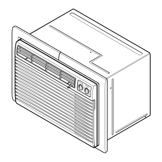
THROUGH THE WALL AIR CONDITIONER
SERVICE MANUAL
CAUTION
- BEFORE SERVICING THE UNIT,
READ THE SAFETY PRECAUTIONS IN THIS MANUAL.
- ONLY FOR AUTHORIZED SERVICE
MODEL: LXA0810ACLY3
LXA1010ACLY3/LXA1011AALY3
LXA1030ACLY3
LXA1210ACLY3/LXA1211AALY3
LXA1230ACLY3
LXA1030AXLY3/LXA1011AHL
LXA1230AXLY3/LXA1211AHL
Advertisement
Table of Contents

Related Manuals for LG LXA0810ACLY3


Summary of Contents for LG LXA0810ACLY3
-
Page 1: Service Manual
THROUGH THE WALL AIR CONDITIONER SERVICE MANUAL CAUTION - BEFORE SERVICING THE UNIT, READ THE SAFETY PRECAUTIONS IN THIS MANUAL. - ONLY FOR AUTHORIZED SERVICE MODEL: LXA0810ACLY3 LXA1010ACLY3/LXA1011AALY3 LXA1030ACLY3 LXA1210ACLY3/LXA1211AALY3 LXA1230ACLY3 LXA1030AXLY3/LXA1011AHL LXA1230AXLY3/LXA1211AHL... -
Page 2: Table Of Contents
CONTENTS 1. PREFACE 2.4 REFRIGERATION CYCLE......12 2.4.1 CONDENSER ........12 1.1 SAFETY PRECAUTIONS .......2 2.4.2 EVAPORATOR ........12 1.2 INSULATION RESISTANCE TEST....2 2.4.3 CAPILLARY TUBE.......12 1.3 SPECIFICATIONS ..........3 1.4 FEATURES .............6 3. INSTALLATION 1.5 CONTROL LOCATIONS .........6 3.1 INSTALLATION REQUIREMENTS....15 2. DISASSEMBLY INSTRUCTIONS 3.2 INSTALLATION..........16 3.3 PROCEDURE A ..........17 2.1 MECHANICAL PARTS........8... -
Page 3: Specifications
1.3 SPECIFICATIONS 1.3.1 FOR LXA0810ACLY3 / LXA1010ACLY3 / LXA1011AALY3 / LXA1210ACLY3 / LXA1211AALY3 MODELS LXA1010ACLY3 LXA1210ACLY3 LXA0810ACLY3 REMARK LXA1011AALY3 LXA1211AALY3 ITEMS POWER SUPPLY 1Ø, 115V, 60Hz COOLING CAPACITY (Btu/h) 8,000 10,000 11,700 INPUT 1,050 1,230 RUNNING CURRENT (A) 11.5 E.E.R (Btu/W.h) - Page 4 1.3.2 FOR LXA1030ACLY3 / LXA1230ACLY3 MODELS LXA1030ACLY3 LXA1230ACLY3 REMARK ITEMS 1Ø, 208/ 230V, 60Hz POWER SUPPLY 9,800/10,000 11,400/11,700 COOLING CAPACITY (Btu/h) 1,030/1,050 1,200/1,230 INPUT 5.2/4.7 6.2/5.8 RUNNING CURRENT E.E.R. (Btu/W.h) 26.7 (DB) 19.4 (WB) INDOOR (°C) OPERATING TEMPERATURE 35 (DB) 23.9 (WB) OUTDOOR (°C) 440(15.0 OZ)
- Page 5 1.3.3 FOR LXA1030AXLY3 / LXA1011AHL / LXA1230AXLY3 / LXA1211AHL LXA1030AXLY3 LXA1230AXLY3 MODELS REMARK ITEMS LXA1011AHL LXA1211AHL POWER SUPPLY 1Ø, 208/ 230V, 60Hz CAPACITY (Btu/h) 9,800/10,000 11,400/11,700 1,030/1,050 1,200/1,230 INPUT COOLING 5.2/4.7 6.2/5.8 RUNNING CURRENT (A) E.E.R. (Btu/W.h) CAPACITY (Btu/h) 9,200/11,200 HEATING INPUT 2,900/3,500...
-
Page 6: Features
1.4 FEATURES • Designed for cooling only. • Side air-intake, side cooled-air discharge. • Powerful and quiet cooling. • Built in adjustable THERMOSTAT. • Top-down chassis for the simple installation and service. • Washable one-touch filter. • Compact size. 1.5 CONTROL LOCATIONS 1.5.1 COOLING ONLY MODEL •... - Page 7 1.5.2 COOLING AND HEATING MODEL • OPERATION Operation ) :Turns the air conditioner off. ) : The low fan speed operation without cooling (heating). Low Cool ( ) : Cooling with the low speed fan operation. High Cool ( ) : Cooling with the high speed fan operation. Low Heat ( ) : Heating with the low speed fan operation.
-
Page 8: Disassembly Instructions
2. DISASSEMBLY INSTRUCTIONS — Before the following disassembly, POWER SWITCH is set to OFF and disconnected the power cord. 2.1 MECHANICAL PARTS 2.1.1 FRONT GRILLE 1. Open the inlet grille upward or downward. 2. Remove the screw which fastens the front grille. 3. -
Page 9: Air Handling Parts
2.2 AIR HANDLING PARTS 2.2.1 ORIFICE, HEATER ASSY AND TURBO FAN 1. Remove the front grille. (Refer to section 2.1.1) 2. Remove the cabinet. (Refer to section 2.1.2) 3. Remove the 2 screws which fasten the evaporator at the left side and the right side. (See Fig. -
Page 10: Shroud
2.2.3 SHROUD 1. Remove the fan. (Refer to section 2.2.2) 2. Remove the screw which fasten the shroud. 3. Remove the shroud. (See Fig. 9) 4. Re-install the component by referring to the removal procedure, above. 2.3 ELECTRICAL PARTS 2.3.1 MOTOR 1. -
Page 11: Power Cord
2.3.4 POWER CORD 1. Remove the control box. (Refer to section 2.1.3) 2. Unfold the control box. (Refer to section 2.3.3) 3. Disconnect the grounding screw from the control box. 4. Disconnect 2 receptacles. 5. Remove a screw which fastens the clip cord. 6. -
Page 12: Refrigeration Cycle
2.4 REFRIGERATION CYCLE CAUTION Discharge the refrigerant system using Freon Recovery System. If there is no valve to attach the recovery system, install one (such as a WATCO A-1) before venting the Freon . Leave the valve in place after servicing the system. 2.4.1 CONDENSER 1. - Page 13 NOTES — Replacement of the refrigeration cycle. 1. When replacing the refrigeration cycle, be sure to 6. Recharge as follows : discharge the refrigerant system using a Freon 1) Refrigeration cycle systems are charged from the recovery System. High-side. If the total charge cannot be put If there is no valve to attach the recovery system, in the High-side, the balance will be put in the install one (such as a WATCO A-1) before venting...
- Page 14 Equipment needed: Vacuum pump, Charging cylinder, Manifold gauge, Brazing equipment. Pinch-off tool capable of making a vapor-proof seal, Leak detector, Tubing cutter, Hand Tools to remove components, Service valve. Figure 18A-Pulling Vacuum Figure 18B-Charging —14—...
-
Page 15: Installation
3. INSTALLATION 3.1 INSTALLATION REQUIREMENTS INSTALLATION HARDWARE If you use an existing wall sleeve, you should measure its dimensions. Install the new air conditioner according to these installation instructions to achieve the best performance. All wall sleeves 2 Size options used to mount the new air conditioner must be in good structural condition and have a rear grille to securely attach the new air conditioner. -
Page 16: Installation
3.2 INSTALLATION NOTE: All wall sleeves used to mount the new Air Conditioner must be in sound structural condition and have a rear grille that securely attaches to sleeve, or CAUTION rear flange that serves as a stop for the Air Conditioner, We strongly recommend the removal of the old wall sleeve and the installation of a new... -
Page 17: Procedure A
3.3 PROCEDURE A Install the new unit into the wall sleeve. If you are using the new LGE sleeve with your unit, To assemble trim, snap the tab of each piece into skip to step 3. Otherwise, install the plastic grille the slot of the other piece as shown below. -
Page 18: Procedure B
3.4 PROCEDURE B Remove the backing from the Horizontal Insulation strip 1 3 / 8 5 / 8 x 27 3 / 16 and attach that to the inside Redirect the louvers at the back of the wall sleeve bottom of the sleeve as shown below. Remove the to 60°... - Page 19 PROCEDURE B To assemble trim, snap the tab of each piece into the slot of the other piece as shown below. Slide trim over the front of the air conditioner until trim is flush with sleeve as shown below. Trim (2 ea) Wall FIG.
-
Page 20: Procedure C
3.5 PROCEDURE C Remove the backing from the Horizontal Insulation strip 1 3 / 8 3 / 8 x 27 3 / 16 and attach that to the inside Redirect the louvers at the back of the wall sleeve bottom of the sleeve as shown below. Remove the to 60°... - Page 21 PROCEDURE C To assemble trim, snap the tab of each piece into the slot of the other piece as shown below. Slide Remove the backing from the 13" shim strips and trim over the front of the air conditioner until trim is attach them as shown below in Fig.
-
Page 22: Electrical Requirements
3.6 ELECTRICAL REQUIREMENTS 3.6.1 ELECTRICAL DATA (FOR 115V MODEL) Line Cord Plug Use Wall Receptacle Power Supply Do not under any circumstances cut Use 15 AMP time Parallel or remove the grounding prong delay fuse or 15 AMP type from the plug. circuit breaker. -
Page 23: Outside Dimensions
4. TROUBLESHOOTING GUIDE 4.1 OUTSIDE DIMENSIONS " " (626mm) (499mm) 4.2 PIPING SYSTEM CONDENSER COILS CAPILLARY TUBE MOTOR COMPRESSOR TURBO FAN EVAPORATOR COILS Following is a brief description of the important components and their functions in the refrigeration system. Refer to Fig. 41 to follow the refrigeration cycle and the flow of the refrigerant in the cooling cycle. ROOM AIR CONDITIONER CYCLE OF REFRIGERATION EVAPORATOR COILS... -
Page 24: Troubleshooting Guide
4.3 TROUBLESHOOTING GUIDE In general, possible trouble is classified in two causes. The one is called Starting Failure which is caused from an electrical defect, and the other is Ineffective Air Conditioning caused by a defect in the refrigeration circuit and improper application. Unit is running but cooling is ineffective Ineffective Cooling Check of cold air circulation... - Page 25 Fails to Start Check of power source. Check of circuit breaker and fuse. Check of control switch Gas leakage of feeler bulb setting. of thermostat Check of control switch. Only compressor fails to Only fan fails to start. start. Improper wiring. Drop of power voltage.
- Page 26 COMPLAINT CAUSE REMEDY Fan motor will not run. No power Check voltage at outlet. Correct if none. Power supply cord Check voltage to rotary switch. If none, check power supply cord. Replace cord if circuit is open. Rotary switch Check switch continuity. Refer to wiring diagram for terminal identification.
-
Page 27: Room Air Conditioner Voltage Limits
COMPLAINT CAUSE REMEDY Compressor will not run, Voltage Check voltage. See the limits on the preceding. but fan motor runs. page. If not within limits, call an electrician. Wiring Check the wire connections, if loose, repair or replace the terminal. If wires are off, refer to wiring diagram for identification, and replace. - Page 28 REMEDY COMPLAINT CAUSE Compressor cycles Voltage Check the voltage. See the limits on the preced- on overload. ing page. If not within limits, call an electrician. Overload Check overload, if externally mounted. Replace if open. (If the compressor temperature is high, remove the overload, cool, and retest.) Fan motor If not running, determine the cause.
-
Page 29: Schematic Diagram
5. SCHEMATIC DIAGRAM 5.1 CIRCUIT DIAGRAM • MODEL : LXA0810ACLY3 / LXA1010ACLY3 / LXA1011AALY3 / LXA1030ACLY3 LXA1210ACLY3 / LXA1211AALY3 / LXA1230ACLY3 GN(GN/YL) MOTOR COMP. P.T.C WIRING DIAGRAM 3854AR3563A PART NO. LOCATION Q'TY DESCRIPTION LXA1010ACLY3 LXA1210ACLY3 LXA0810ACLY3 LXA1030ACLY3 LXA1230ACLY3 PER SET... - Page 30 • MODEL : LXA1030AXLY3 / LXA1011AHL, LXA1230AXLY3 / LXA1211AHL POWER INPUT BK(BR) WH(BL) (Plain) (Ribbed) ROTARY SWITCH GN/YL MOTOR OR(BR) CAPACITOR OR(BR) THERMOSTAT COMP BR(YL) O.L.P FUSE LINK HEATER BI-METAL WIRING DIAGRAM 3854AR3563D THERMOSTAT PART NO. Q'TY LXA1030AXLY3 LXA1230AXLY3 DESCRIPTION PER SET MARKS LXA1011AHL...
-
Page 31: Exploded View
6. EXPLODED VIEW • MODEL: LXA0810ACLY3 / LXA1010ACLY3 / LXA1011AALY3 / LXA1030ACLY3 / LXA1210ACLY3 / LXA1211AALY3 / LXA1230ACLY3 / LXA1030AXLY3 / LXA1011AHL / LXA1230AXLY3 / LXA1211AHL 130900 135312 147582-1 147582-2 147581 435301 152302 749180 135313 352390 559010 349001 349480 753010... -
Page 32: Replacement Parts List
7. REPLACEMENT PARTS LIST R: Service Parts • MODEL: LXA0810ACLY3 / LXA1010ACLY3 / LXA1011AALY3 / LXA1210ACLY3 / LXA1211AALY3 N: Non Service parts PART NO. LOCATION DESCRIPTION REMARK LXA1010ACLY3 LXA1210ACLY3 LXA0810ACLY3 LXA1011AALY3 LXA1211AALY3 249950 CONTROL BOX ASSY, SINGLE 4995A20131Z 4995A20131X 4995A20131Y... - Page 33 • MODEL: LXA1230ACLY3 R: Service Parts N: Non Service parts PART NO. LOCATION DESCRIPTION REMARK LXA1230ACLY3 249950 CONTROL BOX ASSY, SINGLE 4995A20131B 264110 POWER CORD ASSY 2H00677G 266003 SWITCH, ROTARY 2H00598E 269310 THERMOSTAT ASSY 2H01109M W0CZZ CAPACITOR, DRAWING 6120AR2194D 149410 KNOB ASSY 4941A30005B 137215...
- Page 34 • MODEL: LXA1030AXLY3 / LXA1011AHL / LXA1230AXLY3 / LXA1211AHL R: Service Parts N: Non Service parts PART NO. LOCATION DESCRIPTION REMARK LXA1030AXLY3 LXA1230AXLY3 LXA1011AHL LXA1211AHL 249950 CONTROL BOX ASSY, SINGLE 4995A20229G 264110 POWER CORD ASSY 2H00677U 266003 SWITCH, ROTARY 2H00598F 269310 THERMOSTAT ASSY 2H01127D...
- Page 35 February, 2003 P/No.: 3828A20294K Printed in Korea...
Need help?
Do you have a question about the LXA0810ACLY3 and is the answer not in the manual?
Questions and answers