
Related Manuals for LG LWHD8008R.AWYAHDP


Summary of Contents for LG LWHD8008R.AWYAHDP
-
Page 1: Service Manual
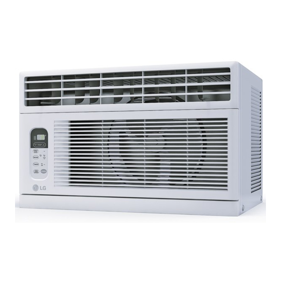
LG Room Air Conditioner SERVICE MANUAL MODELS: LWHD8008R CAUTION • BEFORE SERVICING THE UNIT, READ THE SAFETY PRECAUTIONS IN THIS MANUAL. • ONLY FOR AUTHORIZED SERVICE PERSONNEL. -
Page 2: Table Of Contents
CONTENTS 1. PREFACE ..............................3 1.1 FEATURES..............................3 1.2 SPECIFICATIONS ............................3 1.3 LOCATIONS OF CONTROLS ........................4 1.4 SAFETY PRECAUTIONS ..........................4 1.5 INSULATION RESISTANCE TEST ........................4 2. DISASSEMBLY INSTRUCTIONS ....................5 2.1 MECHANICAL PARTS ..........................5 2.1.1 FRONT GRILLE ............................5 2.1.2 CABINET..............................5 2.1.3 CONTROL BOARD ..........................5 2.2 AIR HANDLING PARTS ..........................6 2.2.1 AIR GUIDE UPPER ..........................6 2.2.2 ORIFICE, TURBO FAN AND FAN ......................6... -
Page 3: Specifications
1. PREFACE This service manual provides various service information, including the mechanical and electrical parts, etc. This room air conditioner was manufactured and assembled under a strict quality control system. The refrigerant is charged at the factory. Be sure to read the safety precautions prior to servicing the unit. 1.1 FEATURES •... -
Page 4: Preface
1-1. PREFACE This service manual provides various service information, including the mechanical and electrical parts, etc. This room air conditioner was manufactured and assembled under a strict quality control system. The refrigerant is charged at the factory. Be sure to read the safety precautions prior to servicing the unit. 1.1 FEATURES •... -
Page 5: Locations Of Controls
1.3 LOCATIONS OF CONTROLS Operation - Turns air conditioner off. High High High Fan - High speed fan operation without cooling. Cool Low Fan - Low speed fan operation without cooling. High Cool - Cooling with high speed fan operation. Cool Low Cool - Cooling with low speed fan operation. -
Page 6: Disassembly Instructions
2. DISASSEMBLY INSTRUCTIONS 2.1 MECHANICAL PARTS 2.1.1 FRONT GRILLE Figure 1 1. Disconnect the unit from source of power. 2. Remove the two knobs by pulling them off. Using a screwdriver, remove the screw that secures the front grille to control board. (See Figure 1) 3. -
Page 7: Air Handling Parts
2.2 AIR HANDLING PARTS Figure 6 2.2.1 AIR GUIDE UPPER 1. Disconnect the unit from the power source. 2. Remove the front grille. (Refer to Section 2.1.1) 3. Remove the cabinet. (Refer to Section 2.1.2) 4. Remove the control board. (Refer to Section 2.1.3) 5. -
Page 8: Motor
2.2.3 MOTOR Figure 10 1. Disconnect the unit from the power source. 2. Remove the front grille. (Refer to Section 2.1.1) 3. Remove the cabinet. (Refer to Section 2.1.2) 4. Remove the control board. (Refer to Section 2.1.3) 5. Remove the air guide upper. (Refer to Section 2.2.1) 6. -
Page 9: Compressor
2.3.2 COMPRESSOR Figure 14 1. Remove the front grille and cabinet. (Refer to Section 2.1) 2. Discharge the refrigerant by using a refrigerant recovery system. 3. Remove the overload protector. (Refer to Section 2.3.1) 4. After discharging the unit completely, unbrace the suction and discharge pipes at the compressor connections. -
Page 10: Power Cord
2.3.6 POWER CORD Figure 18 1. Disconnect the unit from source of power. 2. Remove the front grille. (Refer to Section 2.1.1) 3. Remove the cabinet. (Refer to Section 2.1.2) 4. Remove a screw that secures control board to base pan. (Refer to Section 2.1.3) 5. -
Page 11: Evaporator
2.4.2 EVAPORATOR wise. This will keep oil from foaming and being drawn into the vacuum pump. 1. Remove the cabinet. 2. Discharge the refrigerant by using a refrigerant 6-3. Operate the vacuum pump for 20 to 30 min- recovery system. utes, until 600 micron vacuum is obtained. - Page 12 Equipment needed: Vacuum pump, charging cylinder, manifold gauge, brazing equipment, pinch-off tool capable of making a vapor proof seal, leak detector, tubing cutter, hand tools to remove components and service valve. COMPOUND GAUGE MANIFOLD GAUGE CONDENSER SEE INSETS (HIGH PRESSURE SIDE) BELOW COMPRESSOR EVAPORATOR...
-
Page 13: Installation
3. INSTALLATION This air conditioner is designed with a button-down chassis so it can be easily installed in a window. 3.1 SELECT THE BEST LOCATION 1. To prevent vibration and noise, make sure the unit is installed securely and firmly. 2. -
Page 14: Before Installation
Installation HARDWARE TYPE A: 11EA TYPE B: 4EA TYPE C: 3EA (SHORT SCREW) (WOOD SCREW) (L BACKET) TYPE D: 1EA TYPE E: 1EA TYPE F: 2EA (SEAL STRIP) (SASH SEAL) (GUIDE PANEL) (Adhesive backed) (Not adhesive backed) 3.2.2 BEFORE INSTALLATION 1. - Page 15 3. INSTALL THE AIR CONDITIONER IN THE WINDOW INNER SILL a. Carefully lift the air conditioner and slide it into the TYPE A OUTER SILL INSIDE open window. Make sure the bottom guide of the air CENTER LINE conditioner drops into the notches of the L bracket.
-
Page 16: Electrical Data
REMOVAL FROM WINDOW Turn the air conditioner off, disconnect the power cord, remove the L bracket and the screws installed through the top and bot- tom of the guide panels, and save for reinstallation later. Close the guide panels. Keeping a firm grip on the air conditioner, raise the sash, and carefully tilt the air conditioner backward, draining any condensate water. -
Page 17: Piping System
4.2 PIPING SYSTEM CONDENSER COILS MOTOR CAPILLARY TUBE TURBO FAN EVAPORATOR COILS Figure 32 is a brief description of the important components and their function in what is called the refrigeration system. This will help you to understand the refrigeration cycle and the flow of the refrigerant in the cooling cycle. ROOM AIR CONDITIONER CYCLE OF REFRIGERATION EVAPORATOR COILS... -
Page 18: Troubleshooting Guide
4.3 TROUBLESHOOTING GUIDE In general, possible trouble is classified in two kinds. The one is called Starting Failure which is caused by an electrical defect. The other is Ineffective Air Con- ditioning caused by a defect in the refrigeration circuit and improper application. Unit is running but cooling is ineffective. - Page 19 Fails to Start Check of circuit breaker Check of power source. and fuse. Check of control switch Gas leakage of feeler setting. bulb of thermostat. Check control switch. Compressor fails only to Fan only fails to start. start. Improper wiring. Improper thermostat Drop of power voltage.
- Page 20 ROOM AIR CONDITIONER VOLTAGE LIMITS NAME PLATE RATING MINIMUM MAXIMUM 115V ± 10% 103.5V 126.5V COMPLAINT CAUSE REMEDY Fan motor will not run. No power Check voltage at outlet. Correct if none. Power supply cord Check voltage to rotary switch. If none, check power supply cord.
- Page 21 COMPLAINT CAUSE REMEDY Fan motor noise. If cracked, out of balance, or partially missing, replace it. Blower If cracked, out of balance, or partially missing, replace it. Loose set screw Tighten it. Worn bearings If knocking sounds continue when running or loose, replace the motor.
- Page 22 COMPLAINT CAUSE REMEDY Compressor cycles on Fan motor If not running, determine the cause. Replace if overload. required. Condenser air flow Remove the cabinet, inspect the interior surface restriction of the condenser. If restricted, clean carefully with a vacuum cleaner (do not damage fins) or brush.
-
Page 23: Circuit Diagram
5. CIRCUIT DIAGRAM POWER INPUT BK(BR) WH(BL) (Plain) (Ribbed) ROTARY SWITCH GN(GN/YL) MOTOR OR(BR) CAPACITOR OR(BR) COMP. THERMOSTAT SYNC. M. 3854AR2330A WIRING DIAGRAM ROCKER SWITCH LOCATION Q'TY DESCRIPTION PART NO. PER SET 2H00677P POWER CORD ASSY FAN MOTOR 4681A10016C COMPRESSOR 2520UCAA003 ROTARY SWITCH 2H00154H... -
Page 24: Exploded View
6. EXPLODED VIEW 130910 559011 W48602 749740 554030 149980 267110 349480 731273 135312 352390-1 145200 147582-1 359012 346811 W48602 152302 352390-2 147582-2 135301 354210 130410 135313 W0CZZ 264110 352111 249940 352115 567502 352113 237200 554160 268711-2 263230 35211A 550140 238310 268711-1 249950 —23—... -
Page 25: Service Parts List
Replacement Parts List RADS - 51B LocNo P/NO REMARK Description 130410 3041A20036G BASE ASSEMBLY,WELD 130910 3091AR6055M CABINET ASSEMBLY,SINGLE 135312 3530AR1615B GRILLE ASSEMBLY,FRONT 135313 3530A10039A GRILLE,INLET 147581 4520AR3191A LINK 147582-1 5990AR3190C LOUVER,VERTICAL 147582-2 5990AR3190D LOUVER,VERTICAL 149980 4998AR1608A SHROUD 152302 5231AR2148A FILTER,AIR 237200 3720A20017A PANEL,CONTROL... - Page 26 7. SERVICE PARTS LIST PART NO LOCATION NO DESCRIPTION Remark RAD-61A 130410 BASE ASSEMBLY,SINGLE 3041A20036N 130910 CABINET ASSY,SINGLE 3091AR6055M 135312 GRILLE ASSY,FRONT(SINGLE) 3531A20087B 135313 GRILLE ASSY,INLET 3530A10039A 147581 LINK 4520AR3191A 147582-1 VANE,VERITCAL 5990AR3190C 149980 SHROUD 4998A10025A 152302 FILTER ASSY,A/C 5231AR2148A 238310 ESCUTCHEON 3831A10001F...
- Page 27 January, 2008 Printed in China...
Need help?
Do you have a question about the LWHD8008R.AWYAHDP and is the answer not in the manual?
Questions and answers