Advertisement
Table of Contents
- 1 Table of Contents
- 2 Warranty
- 3 Safety Instructions
- 4 Parts Numbers and Illustrations
- 5 Parts List
- 6 Parts List
- 7 Maintenance
- 8 Hardware Packing List
- 9 Overview Drawing
- 10 Assembly Instructions
- 11 Cable Loop Diagram
- 12 Pulleys and Lat Bar Cable Installation
- 13 Pulleys and Pec Cable Installation
- 14 Pulleys and Leg Extension Cable Installation
- 15 Warm up and Cool down Routine
- Download this manual
Advertisement
Table of Contents

Related Manuals for Life Gear G2


Summary of Contents for Life Gear G2
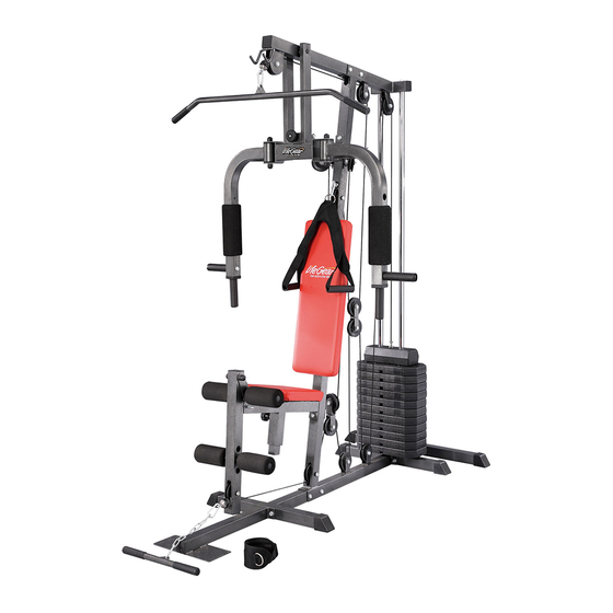
- Page 1 LifeGear G2 /HOME GYM ITEM NO.: 63110 OWNER’S MANUAL IMPORTANT: Read all instructions carefully before using this product. Retain this owner’s manual for future reference. The specifications of this product may vary from this photo, subject to change without notice.
-
Page 2: Table Of Contents
TABLE OF CONTENTS WARRANTY ------------------------------------------------------------------------------- 1 SAFETY INSTRUCTIONS ------------------------------------------------------------- 2 PARTS NUMBERS AND ILLUSTRATIONS --------------------------------------- 3 PARTS LIST ------------------------------------------------------------------------------- 4 MAINTENANCE -------------------------------------------------------------------------- 5 HARDWARE PACKING LIST ---------------- ---------------------------------------- 6 OVERVIEW DRAWING ----------------------------------------------------------------- 9 ASSEMBLY INSTRUCTIONS --------------------------------------------------------- 10 CABLE LOOP DIAGRAM--------------------------------------------------------------- 20 PULLEYS AND LAT BAR CABLE INSTALLATION ------------------------------ 21 PULLEYS AND PEC CABLE INSTALLATION ------------------------------------ 26 PULLEYS AND LEG EXTENSION CABLE INSTALLATION ------------------ 30... -
Page 3: Safety Instructions
SAFETY INSTRUCTIONS Basic precautions should always be followed, including the following safety instructions when using this home gym: Read all instructions before using this home gym. Read all the instructions in this manual and do warm up exercises before using this home gym. -
Page 4: Parts Numbers And Illustrations
PARTS NUMBERS AND ILLUSTRATIONS... -
Page 5: Parts List
PARTS LIST Description Qty No. Description 001 Top Frame 1 033 Weight Stack 002 Main Base Tube 1 034 Big Washer 003 Seat Frame 1 035 Plastic Bushing 004 Weight Stack Sliding Rod 2 036 Pin 005 Main Support Tube 1 037 Guide Rod 006 Rear Base Tube 1 038 L-Shaped Pin... -
Page 6: Maintenance
PARTS LIST Description Qty No. Description 065 Washer Ø8 4 075 Washer Ø6 066 Hexagon Head Bolt M10x25 6 076 Hexagon Head Bolt M12x115 067 Hexagon Head Bolt M10x75 11 077 Seat Support Frame Plastic Bushing 068 Hexagon Head Bolt M10x70 5 078 Ankle Strap 069 Hexagon Head Bolt M10x65 2 079 Round Knob... -
Page 7: Hardware Packing List
HARDWARE PACKING LIST Hardware (18) Lock Bar (34) Big Washer (36) Pin (38) L-Shaped Pin 1 PC 1 PC 1 PC 1 PC (54) Ring Pin (55) Coil Chain (58) Hook (59) Nylon Lock 1 PC 1 PC 4 PCS Nut M12 2 PCS (60) Nylon Lock... - Page 8 Plastic Parts (35) Plastic Bushing (39) Rubber Bumper (40) Knob M10 (43) Pulley Bushing 1 PC 2 PCS 1 PC 6 PCS (51) Base Tube End Cap (79) Round Knob (82) Hexagon Nut (83) Hexagon Nut 50x50 1 PC Cap M12 Cap M10 6 PC 4 PCS...
- Page 9 Foam Roller (52) Foam Roll (53) Pec Foam Roll Ø23xØ80x160 Ø90x245 4 PCS 2 PCS Weight Stack Pack (32) Top Weight Stack (33) Weight Stack (Approximately 4.5 kgs/10.0 lbs) (Approximately 5.7 kgs/12.5 lbs) 1 PC 11 PCS Tools Wrench 14-10 Wrench 14-17 Wrench 19-17 1 PC...
-
Page 10: Overview Drawing
OVERVIEW DRAWING... -
Page 11: Assembly Instructions
ASSEMBLY INSTRUCTIONS NOTE: It is recommended that you always use the aid of a second person when assembling the home gym. Tool: 2 Wrenches (19-17) Step 1 Attach the Weight Sliding Rod Tube (14) onto the rear end of the Main Base Tube (2) and Rear Base Tube (6) with two M10x75 Hexagon Head Bolts (67), two M10 Nylon Lock Nuts (60), and four Ø10 Washers (64). - Page 12 Tool: 2 Wrenches (19-17) 1 Allen Wrench (6mm) Step 2 Slide two Rubber Bumpers (39) onto the Weight Stack Sliding Rods (4). Then insert two Weight Stack Sliding Rods (4) into the holes of the Weight Sliding Rod Tube (14) and secure with two M10x20 Bolts (63).
- Page 13 Step 3 Install each Weight Stack (33) onto the Weight Stack Sliding Rods (4). NOTE: Ensure that each weight stack’s selector pin slot faces downward. Slide the Plastic Bushing (35) onto the Guide Rod (37) and align pin hole. Secure the Plastic Bushing (35) onto the Guide Rod (37) by inserting the Pin (36) through into the holes of the Guide Rod (37) and Plastic Bushing (35).
- Page 14 Tool: 2 Wrenches (19-17) Step 4 Insert each Weight Stack Sliding Rod (4) into the corresponding hole in the Top Frame (1). Secure Weight Stack Sliding Rods (4) in the Top Frame (1) using two Ø10 Washers (64) and two M10x25 Hexagon Head Bolts (66). Tighten bolts with the Wrench provided. Attach the Top Frame (1) onto the Main Support Tube (5) with two M10x75 Hexagon Head Bolts (67), two M10 Nylon Lock Nuts (60), and four Ø10 Washers (64).
- Page 15 Tool: 2 Wrenches (19-17) Step 5 Attach the Support Tube (8) onto the Main Support Tube (5) with two M10x70 Hexagon Head Bolts (68), two M10 Nylon Lock Nuts (60), and four Ø10 Washers (64). Tighten bolt and nut with two Wrenches provided. Hardware: 2 Hexagon Head Bolts (M10x70) 4 Washers (Ø10)
- Page 16 Tool: 2 Wrenches (19-17) Step 7 Attach the Leg Extension Tube (13) onto the clevis of the Seat Support Tube (15) with one M10x75 Hexagon Head Bolt (67), one M10 Nylon Lock Nut (60), and two Ø10 Washers (64). Tighten bolt and nut with two Wrenches provided. Install two M10 Hexagon Nut Caps (83) onto the M10x75 Hexagon Head Bolt (67) and M10 Nylon Lock Nut (60).
- Page 17 Tool: 1 Wrench (14-10) Step 8 Attach the Backrest (27) onto the Main Support Tube (5) with two Ø8 Washer (65) and two M8x65 Hexagon Head Bolts (73). Tighten bolts with the Wrench provided. Attach the Seat Pad (28) onto the Seat Frame (3) with four M6x16 Hexagon Head Bolts (74) and four Ø6 Washers (75).
- Page 18 Step 9 Slide the Foam Roll Tube (25) through the round hole on the clevis of the Seat Support Tube (15). Slide two Ø23xØ80x160 Foam Rolls (52) onto both ends of the Foam Roll Tube (25). Slide the Foam Roll Tube (25) through the round hole on the Leg Extension Tube (13). Slide two Ø23xØ80x160 Foam Rolls (52) onto both ends of the Foam Roll Tube (25).
- Page 19 Tool: 1 Wrench (14-10) 1 Wrench (14-17) Step 10 Attach the Support Frame for Pec Arm (7) onto the Top Frame (1) with one Top Shaft (26) and two M8x20 Hexagon Head Bolts (71). Tighten bolt with the Wrench provided. Attach the Lock Bar (18) onto the clevis of the Support Tube (8) with one M8x45 Hexagon Head Bolt (72), one M8 Nylon Lock Nut (61), and two Ø8 Washers (65).
- Page 20 Tool: 2 Wrenches (19-17) Step 11 Attach the Right Pec Arm (10) onto the Support Frame for Pec Arm (7) with one M12x115 Hexagon Head Bolt (76), one M12 Nylon Lock Nut (59), and two Ø12 Washers (62). Tighten bolt and nut with two Wrenches provided. Install two M12 Hexagon Nut Caps (82) onto the M12x115 Hexagon Head Bolt (76) and M12 Nylon Lock Nut (59).
-
Page 21: Cable Loop Diagram
CABLE LOOP DIAGRAM 64 60... -
Page 22: Pulleys And Lat Bar Cable Installation
PULLEYS AND LAT BAR CABLE INSTALLATION Lat Bar Cable Tool: 64 60 2 Wrenches (19-17) Step 1 Insert the Lat Bar Cable (31) around the Pulley (44) with the big ball end of the cable at the front of the Pulley (44). Then attach the Pulley (44) onto the Top Frame (1) with one M10 Nylon Lock Nut (60), one M10x45 Hexagon Head Bolt (70), and two Ø10 Washers (64). - Page 23 Tool: 2 Wrenches (19-17) Step 2 Pull the Lat Bar Cable (31) towards to the second Pulley (44) and draw it around the Pulley (44). Then attach the Pulley (44) onto the Top Frame (1) with one M10 Nylon Lock Nut (60), one M10x45 Hexagon Head Bolt (70), and two Ø10 Washers (64).
- Page 24 Tool: 2 Wrenches (19-17) 64 60 Step 3 Pull the Lat Bar Cable (31) downwards. Draw the Lat Bar Cable (31) around the Pulley (44). Then attach the Pulley (44) onto the Pulley Plates (20) with one M10 Nylon Lock Nut (60), one M10x45 Hexagon Head Bolt (70), and two Ø10 Washers (64).
- Page 25 Tool: 2 Wrenches (19-17) Step 4 Pull the Lat Bar Cable (31) upwards. Draw the Lat Bar Cable (31) around the Pulley (44). Then attach the Pulley (44) onto the Main Support Tube (5) with one M10 Nylon Lock Nut (60), one M10x70 Hexagon Head Bolt (68), two Ø10 Washers (64), and two Pulley Bushings (43).
- Page 26 Step 5 Connect the Hook (58) to the ball stopper end of the Lat Bar Cable (31) and Abdominal Strap (81). PLEASE REFER TO THE “CABLE LOOP DIAGRAM” SECTION ON PAGE Hardware: Accessory: 1 Hook 1 Abdominal Strap ․․․․․․․․․․․․․․․․․․․․․․․․․․․․․․․․․․․․․․․․ Step 6 Connect the Hook (58) to the ball stopper end of the Lat Bar Cable (31) and Lat Bar (16).
-
Page 27: Pulleys And Pec Cable Installation
PULLEYS AND PEC CABLE INSTALLATION Pec Cable Tool: 2 Wrenches (19-17) Step 1 Attach one end of the Pec Cable (30) onto the Left Pec Arm (11) with one M10 Nylon Lock Nut (60), one M10x25 Hexagon Head Bolt (66), and two Ø10 Washers (64). Tighten bolt and nut with two Wrenches provided. - Page 28 Tool: 2 Wrenches (19-17) Step 2 Attach the Pec Pulley Bracket (21) onto the left clevis of the Main Support Tube (5) with one M10 Nylon Lock Nut (60), one M10x65 Hexagon Head Bolt (69), and two Ø10 Washers (64). Tighten bolt and nut with two Wrenches provided.
- Page 29 Tool: 2 Wrenches (19-17) Step 3 Pull the Pec Cable (30) downwards to the Crossed Double Floating Pulley Bracket (19). Draw the Pec Cable (30) around the Pulley (44) on the Crossed Double Floating Pulley Bracket (19). Then attach the Pulley (44) onto the Crossed Double Floating Pulley Bracket (19) with one M10 Nylon Lock Nut (60), one M10x45 Hexagon Head Bolt (70), and two Ø10 Washers (64).
- Page 30 Pulley: 2 Pulleys Hardware: 8 Washers (Ø10) 4 Nylon Lock Nut (M10) 2 Hexagon Head Bolt (M10x45) 1 Hexagon Head Bolt (M10x65) 1 Hexagon Head Bolt (M10x25)
-
Page 31: Pulleys And Leg Extension Cable Installation
PULLEYS AND LEG EXTENSION CABLE INSTALLATION Leg Extension Cable Tool: 2 Wrenches (19-17) Step 1 Insert the Leg Extension Cable (29) to the Pulley (44). Then attach the Pulley (44) onto the Leg Extension Tube (13) with one M10 Nylon Lock Nut (60), one M10x70 Hexagon Head Bolt (68), two Ø10 Washers (64), and two Pulley Bushings (43). - Page 32 Tool: 2 Wrenches (19-17) Step 2 Pull the Leg Extension Cable (29) towards and insert it to the second Pulley (44). Then attach the Pulley (44) onto the Main Support Tube (5) with one M10 Nylon Lock Nut (60), one M10x70 Hexagon Head Bolt (68), two Ø10 Washers (64), and two Pulley Bushings (43). Tighten bolt and nut with two Wrenches provided.
- Page 33 Tool: 2 Wrenches (19-17) Step 3 Pull the Leg Extension Cable (29) upwards to the Crossed Double Floating Pulley Bracket (19). Draw the Leg Extension Cable (29) around the Pulley (44) on the Crossed Double Floating Pulley Bracket (19). Then attach the Pulley (44) onto the Crossed Double Floating Pulley Bracket (19) with one M10 Nylon Lock Nut (60), one M10x45 Hexagon Head Bolt (70), and two Ø10 Washers (64).
- Page 34 Tool: 2 Wrenches (19-17) Step 4 Pull the Leg Extension Cable (29) downwards to the Pulley (44). Draw the Leg Extension Cable (29) around the Pulley (44). Then attach the Pulley (44) onto the Main Base Tube (2) with one M10 Nylon Lock Nut (60), one M10x45 Hexagon Head Bolt (70), and two Ø10 Washers (64).
- Page 35 Tool: 2 Wrenches (19-17) Step 5 Pull the Leg Extension Cable (29) upwards to the Pulley Plates (20). Draw the Leg Extension Cable (29) around the Pulley (44) on the Pulley Plates (20). Then attach the Pulley (44) onto the Pulley Plates (20) with one M10 Nylon Lock Nut (60), one M10x45 Hexagon Head Bolt (70), and two Ø10 Washers (64).
- Page 36 Tool: 2 Wrenches (19-17) Step 6 Pull the Leg Extension Cable (29) downwards to the Pulley (44). Draw the Leg Extension Cable (29) around the Pulley (44). Then attach the Pulley (44) onto the Main Base Tube (2) with one M10 Nylon Lock Nut (60), one M10x45 Hexagon Head Bolt (70), and two Ø10 Washers (64).
- Page 37 Tool: 2 Wrenches (19-17) Step 7 Pull the Leg Extension Cable (29) upwards to the Pulley (44). Draw the Leg Extension Cable (29) around the Pulley (44). Then attach the Pulley (44) onto the Top Frame (2) with one M10 Nylon Lock Nut (60), one M10x45 Hexagon Head Bolt (70), and two Ø10 Washers (64).
- Page 38 Step 8 Pull the Leg Extension Cable (29) downwards to the Guide Rod (37). Thread the bolt at the end of the Leg Extension Cable (29) into the opening on top of the Guide Rod (37) to secure the cable. PLEASE REFER TO THE “CABLE LOOP DIAGRAM”...
- Page 39 Step 9 Connect the Hook (58) to the ball stopper end of the Leg Extension Cable (29) and Coil Chain (55). Connect the Hook (58) to the Coil Chain (55) and Arm Curl Handle (17) or Ankle Strap (78). Hardware: 1 Coil Chain 2 Hooks Accessory:...
-
Page 40: Warm Up And Cool Down Routine
WARM UP AND COOL DOWN ROUTINE A good exercise program consists of a warm-up, aerobic exercise, and a cool down. Do the entire program at least two to three times a week, resting for a day between workouts. After several months you can increase your workouts to four or five times per week. AEROBIC EXERCISE is any sustained activity that sends oxygen to your muscles via your heart and lungs. - Page 41 SIDE STRETCHES Open your arms to the side and lift them until they are over your head. Reach your right arm as far toward the ceiling as you can for one count. Repeat this action with your left arm. QUADRICEPS STRETCH With one hand against a wall for balance, reach behind you and pull your right foot up.
- Page 42 TOE TOUCHES Slowly bend forward from your waist, letting your back and shoulders relax as you stretch toward your toes. Reach as far as you can and hold for 15 counts. HAMSTRING STRETCHES Extend your right leg. Rest the sole of your left foot against your right inner thigh.
Need help?
Do you have a question about the G2 and is the answer not in the manual?
Questions and answers