Samsung AQB09JJWC Service Manual
Split-type air conditioner
Hide thumbs
Also See for AQB09JJWC:
- User manual (26 pages) ,
- User manual (26 pages) ,
- Service manual (88 pages)
Table of Contents
Advertisement
For more information, Please access to our service web site(http://itself.sec.samsung.co.kr)
26006A(2)_co.indd
1
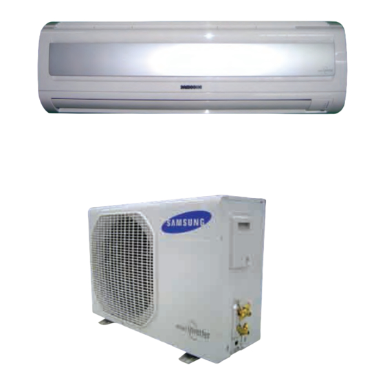
AIR CONDITIONER
AQB09JJWC/AQB12JJWC
UQB09JJWC/UQB12JJWC
SPLIT-TYPE AIR CONDITIONER
Basic : SH12BWHA
Model : AQB09JJWC/AQB12JJWC
Model Code : AQB09JJWC/AQB12JJWC
UQB09JJWC/UQB12JJWC
THE FEATURE OF PRODUCT
Energy Saving Function
■
High Impressive & Elegant Design
■
Silver Nano Pre-Filter
■
Multi Functional Cleaning System
■
: The Chatechin filter and activated Deodorizing filter
■
are adopted.
Human Touch Remote control
■
2006-04-14
ソタネト 5:11:24
Advertisement
Table of Contents

Related Manuals for Samsung AQB09JJWC


Summary of Contents for Samsung AQB09JJWC
- Page 1 Silver Nano Pre-Filter ■ Multi Functional Cleaning System ■ AQB09JJWC/AQB12JJWC : The Chatechin filter and activated Deodorizing filter ■ are adopted. Human Touch Remote control ■ UQB09JJWC/UQB12JJWC For more information, Please access to our service web site(http://itself.sec.samsung.co.kr) 26006A(2)_co.indd 2006-04-14 ソタネト 5:11:24...
-
Page 2: Table Of Contents
5-1 Indoor Unit ..............................5-2 Outdoor Unit ............................. 5-3 Ass’y Control In ............................5-4 Ass’y Control Out ............................16. Electrical Parts List ..........................17. Wiring Diagram ............................7-1 Indoor Unit ..............................7-2 Outdoor Unit ............................Samsung Electronics 26006A(2)_1.indd 2006-04-14 ソタネト 5:12:25... - Page 3 Contents 18. Schematic Diagram ..........................8-1 Indoor Unit ..............................8-2 Outdoor Unit ............................19. Circuit Descriptions ..........................9-1 PCB Circuit Descriptions .......................... 9-2 Refrigerating Cycle Diagram ........................10. PCB Diagram 10-1 ............................. 10-1 Indoor PCB 10-1 ............................... 10-2 Outdoor Inverter PCB 10-2 ..........................
-
Page 4: Precautions
Do not place a cloth or other materials over it. ● Remove the batteries if you don’t use the remote control for a long time. (If applicable) ● Use the remote control within 7 meters from the indoor unit. (If applicable) Samsung Electronics 26006A(2)_1.indd 2006-04-14... -
Page 5: Disposing Of The Unit
● Young children or infirm persons should be always supervised when they use the air conditioner. ● Max current is measured according to IEC standard for safety. ● Current is measured according to ISO standard for energy efficiency. Samsung Electronics 26006A(2)_1.indd 2006-04-14... -
Page 6: Product Specifications
■ Multi functional cleaning system Multi Chatechin filter and activated Deordorizing filter are adopted. ■ Human touch remote control The use of air conditioner is easier and more convenient by the human touch remote control of new design. Samsung Electronics 26006A(2)_1.indd 2006-04-14 ソタネト 5:12:26... -
Page 7: Product Specifications
2-2 Product Specifications Model AQB09JJWC AQB12JJWC Indoor unit Outdoor unit Indoor unit Outdoor unit Item Type Wall-mounted Wall-mounted Cooling(Min/Std/Max) Btu/hr 3,100/9,000/11,900 3,100/12,000/14,300 Heating(Min/Std/Max) Btu/hr 3,100/12,000/17,000 3,100/13,600/18,700 Dehumidifying Cooling 4.5/6.0/7.5 31.5/22/13.0 4.5/6.5/8.0 31.5/22/13.0 m³/min Air Volume (H/M/L) Performance Heating 5.5/7.0/8.5 31.5/22/13.0 5.5/7.5/9... -
Page 8: The Comparative Specifications Of Product
17 lb Net Weight Outdoor Unit 78 lb 79 lb Indoor Unit 32.5x11.2x7.4 inch 32.5x11.2x7.4 inch Outer Dimension (WidthxHeightxDepth) Outdoor Unit 31.1x21.6x11.2 inch 28.4x21.6x10.4 inch Indoor Unit 43dB 43dB Noise Outdoor Unit 53dB 53dB Samsung Electronics 26006A(2)_1.indd 2006-04-14 ソタネト 5:12:27... -
Page 9: Accessory And Option Specifications
Remote Control DB93-03012K Batteries for Remote Control DB47-90024A Indoor Unit User’s Manual DB98-25865A Installation Manual DB98-25853A Service Manual DB98-26006A Drain Plug DB67-20011A Outdoor Unit Rubber Leg DB73-00179A 3-wire Power Cable Accessory 2-wire Assembly Cable Samsung Electronics 26006A(2)_1.indd 2006-04-14 ソタネト 5:12:29... - Page 10 DB96-10453B Assembly Pipe,ø3/8 inch(9.52mm) DB96-10453F PE T3 Foam Tube Insulation DB72-50165A Vinyl Tape, Width 2 inch(50mm) DB72-00459A Accessory Drain Plug DB67-20011A Rubber Leg DB73-00179A Pipe Clamps A DB39-20224A Pipe Clamps B DB39-20224B Cement Nail Samsung Electronics 26006A(2)_1.indd 2006-04-14 ソタネト 5:12:30...
- Page 11 Product Specifications Accessories(cont.) Item Descriptions Code-No. Q'TY Remark M4x16 Tapping Screws 6002-000215 Accessory Drain Hose, length 78.7 inch(2m) DB62-00487A Putty 3.28oz(100g) DB98-10568A Samsung Electronics 26006A(2)_1.indd 2006-04-14 ソタネト 5:12:30...
-
Page 12: Alignment And Adjustments
Indoor fan motor malfunction 3-4P EEPROM error Option Setting Option error Option Setting (option wasn’t set up or option data error) Remote Control on/off Outdoor unit error Outdoor Unit Power Reset Lamp on, Lamp off, Lamp blink Samsung Electronics 26006A(2)_1.indd 2006-04-14 ソタネト 5:12:30... - Page 13 Connect the sensor to CN43, supply power, and measure the voltage of #1 and #2 of the CN43 connector. Poor ASS'Y PCB Replace Below 0.5V? Poor ASS'Y PCB Replace Over 4.9V? MICOM Error or Connector(CN43) check Samsung Electronics 26006A(2)_1.indd 2006-04-14 ソタネト 5:12:31...
- Page 14 3. Assemble the room pipe sensor to PCB, plug in, and check the voltage of connector 3 and 4. If the resistance is below 0.5V or over 4.9V, replace the indoor Main PCB. (short or disconnected in the PCB board) Samsung Electronics 26006A(2)_1.indd 2006-04-14 ソタネト...
- Page 15 Test rod location Normal voltage PCB CN72 Condition pin #3 and #5 Fan operating About AC180V Replace Motor Motor Fan-Capacitor is out of order Fan-Capacitor Fan motor should be replaced. Fan motor is out of order. Samsung Electronics 26006A(2)_1.indd 2006-04-14 ソタネト 5:12:32...
-
Page 16: Outdoor Led Error Display And Check Method
Power ON reset(1sec) • PCB pattern (Open/Short) Capacity miss match • Option code Test Operation at Cooling Mode • Operating mode Test Operation at Heating Mode • Operating mode LED ON, LED OFF, LED BLINK Samsung Electronics 26006A(2)_1.indd 2006-04-14 ソタネト 5:12:32... -
Page 17: Setting Option Setup Method
Setting Option SEG4. Push the button to set the display panel to Every time you push the button, the display panel reads ➡ ➡ ➡ . . . repeatedly. ➡ ➡ ➡ ➡ ➡ ➡ ➡ Samsung Electronics 26006A(2)_1.indd 2006-04-14 ソタネト 5:12:37... - Page 18 Setting Option SEG10. Push the button to set the display panel to Every time you push the button, the display panel reads ➡ ➡ ➡ . . . repeatedly. ➡ ➡ ➡ ➡ ➡ ➡ ➡ Samsung Electronics 26006A(2)_1.indd 2006-04-14 ソタネト 5:12:47...
- Page 19 If all lamps of indoor unit are flickering, Plug out, plug in power plug again and press ON/OFF key to retry. If the unit is not working properly or all lamps are continuously flickering after setting the option code, see if the correct option code is set up for its model. Samsung Electronics 26006A(2)_1.indd 2006-04-14...
-
Page 20: Option Items
Operating Instructions and Installation Alignment and Adjustments ■ OPTION ITEMS REMOCON SEG1 SEG2 SEG3 SEG4 SEG5 SEG6 SEG7 SEG8 SEG9 SEG10 MODEL AQB09JJWC AQB12JJWC Samsung Electronics 26006A(2)_1.indd 2006-04-14 ソタネト 5:12:53... -
Page 21: Disassembly And Reassembly
2) Open the Front Grille by pulling right and left sides of the hook. 3) Loosen 1 of the right screw(CCW) and detach the Terminal Cover. 4) Detach the thermistor from the Front Grille. 5) Loosen 3 fixing screws(CCW) of Front Grille. Samsung Electronics 26006A(2)_1.indd 2006-04-14 ソタネト 5:12:53... - Page 22 (Inclusion Power Cord) 2) Detach the outdoor unit connection wire from the Terminal Block. 3) Loosen 4 fixing screws(CCW) of Ass'y Control-In. Tray Drain 1) Pull Tray Drain out from the Back Body. Samsung Electronics 3-11 26006A(2)_1.indd 2006-04-14 ソタネト 5:12:54...
- Page 23 Fan Motor 1) Loosen the fixing screw(CCW). & 2) Detach the Fan Motor from the Fan. Cross Fan 3) Detach the Fan From the left Holder Bearing. Samsung Electronics 26006A(2)_1.indd 2006-04-14 ソタネト 5:12:55...
-
Page 24: Outdoor Unit
Cabinet Front lower to detach the Cabinet Front. 3) Detach the Cabinet Front like the picture on the right side. 4) Loosen 1 screw(CCW) fixed to assemble Plate Control Out with Cabinet-Side RH. Samsung Electronics 26006A(2)_1.indd 2006-04-14 ソタネト 5:12:56... - Page 25 Remark 5) Loosen 2 fixing screws(CCW) on the rear side of Cabinet-Side RH. 6) Loosen 3 screws(CCW) fixed to assemble Bracket Valve with Cabinet-Side RH. 7) Loosen 2 fixing screws(CCW) of Cabinet Side LF. Samsung Electronics 26006A(2)_1.indd 2006-04-14 ソタネト 5:12:57...
- Page 26 1) Detach the Motor Wire from the PCB of Ass'y Control Out. 2) Detach several connectors from the PCB of Ass'y Control Out. 3) Detach 2 Connect Wires from Reactor. 4) Loosen 1 screw(CCW) fixed to assemble Ass'y Control Out with Partition. Samsung Electronics 26006A(2)_1.indd 2006-04-14 ソタネト 5:12:58...
- Page 27 2) Detach the Terminal Cover and detach the Connect Comp Wire from Compressor. 3) Disassemble the Felt Comp Sound. 4) Loosen the 3 bolts(CCW) at the bottom of Compressor like the picture on the right side. Samsung Electronics 26006A(2)_1.indd 2006-04-14 ソタネト 5:12:58...
- Page 28 MEMO Samsung Electronics 26006A(2)_1.indd 2006-04-14 ソタネト 5:12:59...
-
Page 29: Exploded Views And Parts List
5. Exploded Views and Parts List 5-1 Indoor Unit Samsung Electronics 26006A(2)_1.indd 2006-04-14 ソタネト 5:13:01... - Page 30 Exploded Views and Parts List ■ Parts List Q'TY Code No. Description Specification SA/SNA AQB09JJWC AQB12JJWC DB94-00454B ASS’Y-BACK BODY ASS’Y DB61-01632A BACK-BODY HIPS DB69-00834A CUSHION-BACK BODY DB61-01634A SUPPORTER-EVAP RH HIPS DB31-00219A MOTOR-IN YDK-016S1408-01 DB94-00456A ASS’Y-CROSS FAN OD92x635 DB97-02075A ASS’Y-BOLT SPECIAL ASS’Y...
-
Page 31: Outdoor Unit
5-2 Outdoor Unit 19-1 20-2 19-2 20-1 20-3 17-3 17-4 17-5 17-2 17-1 Samsung Electronics 26006A(2)_1.indd 2006-04-14 ソタネト 5:13:16... - Page 32 FUJIKOKI 20-3 DB62-02283A VALVE SERVICE R410A,SANHUA,1/4” DB93-03453D ASS’Y CONTROL OUT ASS’Y DB93-03453E ASS’Y CONTROL OUT ASS’Y DB61-01861A GUIDE SCREEN P.E.H 100% DB63-01479A FELT COMP BASE FELT DB32-00083K THERMISTOR OUT/DIS ASS’Y DB32-00081D THERMISTOR COND ASS’Y Samsung Electronics 26006A(2)_1.indd 2006-04-14 ソタネト 5:13:22...
-
Page 33: Ass'y Control In
C/W STEP MOTOR UP/DOWN ASS’Y DB32-00020D ASS’Y-THERMISTOR 4P(103AT) DB63-00851A COVER LAMP ABS(V0) DB73-00242B RUBBER-BAND RUBBER DB39-00765T CONNECT WIRE-L DB39-01193A CONNECT WIRE-N SKYBLU,3P DB39-01210B CONNECT WIRE-COMM RED/BLU DB68-01975A LABLE CAUTION TETRON25 DB39-01213A C/W DISPLAY PCB ASS’Y Samsung Electronics 26006A(2)_1.indd 2006-04-14 ソタネト 5:13:22... - Page 34 MEMO Samsung Electronics 26006A(2)_1.indd 2006-04-14 ソタネト 5:13:22...
-
Page 35: Ass'y Control Out
5-4 Ass'y Control Out ■ UQB09JJWC : DB93-03453E UQB12JJWC : DB93-03453D Samsung Electronics 26006A(2)_1.indd 2006-04-14 ソタネト 5:13:23... - Page 36 INSULATOR MICA DB39-01198A C/W-DISP(5P) DB98-24813A ASS’Y-THERMAL GREASE DB39-00604W LEAD CONNECTOR-N SKYBLU DB39-00604X LEAD CONNECTOR-L 6009-001001 SCREW SPECIAL SCREW EARTH DB61-00206A HOLDER WIRE CLAMP SGCC-M,T0.5 6002-001149 SCREW TAPPING M4x10 2S PH+ DB65-10088D CABLE TIE NYLON66 Samsung Electronics 26006A(2)_1.indd 2006-04-14 ソタネト 5:13:25...
-
Page 37: Electrical Parts List
C-CER,CHIP 1nF,10%,50V,X7R,1608 C501 2203-005249 C-CER,CHIP 100nF,10%,50V,X7R,1608 C502 2203-000189 C-CER,CHIP 100nF,+80-20%,25V,Y5V,1608 C503 2203-000189 C-CER,CHIP 100nF,+80-20%,25V,Y5V,1608 C504 2203-000189 C-CER,CHIP 100nF,+80-20%,25V,Y5V,1608 C505 2203-000189 C-CER,CHIP 100nF,+80-20%,25V,Y5V,1608 C506 2203-000189 C-CER,CHIP 100nF,+80-20%,25V,Y5V,1608 C507 2203-000189 C-CER,CHIP 100nF,+80-20%,25V,Y5V,1608 C508 2203-000189 C-CER,CHIP 100nF,+80-20%,25V,Y5V,1608 Samsung Electronics 26006A(2)_1.indd 2006-04-14 ソタネト 5:13:25... - Page 38 MB90F823,-,80 P,5 V,24 MHz,STM-0581-OA,24,16,QFP,QFP, 14x20 mm,16,-40~85 IC05 0506-000175 TR-ARRAY 2003,NPN,7,1W,SOP-16,ST,1000 IC06 0506-000175 TR-ARRAY 2003,NPN,7,1W,SOP-16,ST,1000 IC07 1003-001462 IC-SOURCE DRIVER TD62783AFW,SOL,18P,-,8,-500mA,TP,PLASTIC,50V, -40TO85C,1.47,50V,- IC08 0506-000175 TR-ARRAY 2003,NPN,7,1W,SOP-16,ST,1000 IC09 1103-001175 IC-EEPROM 93LC56,128x16,SOP,8P,5x4mm,2.5/6.0V,-40to+85C IC18 1006-001312 IC-BUS TRANSCEIVER 1487,SO,8P,4.9x3.8 mm,SINGLE,ST,PLASTIC,5V,-, -40to+85CC,520mW,1,-,1,1.5/5.25V,- Samsung Electronics 26006A(2)_1.indd 2006-04-14 ソタネト 5:13:26...
- Page 39 R-CHIP 47Kohm,5%,1/4W,TP,3216 R205 2007-000078 R-CHIP 1Kohm,5%,1/10W,TP,1608 R206 2007-000944 R-CHIP 47Kohm,5%,1/4W,TP,3216 R206 2007-000078 R-CHIP 1Kohm,5%,1/10W,TP,1608 R207 2007-000944 R-CHIP 47Kohm,5%,1/4W,TP,3216 R208 2007-000944 R-CHIP 47Kohm,5%,1/4W,TP,3216 R209 2007-000090 R-CHIP 10Kohm,5%,1/10W,TP,1608 R210 2007-000078 R-CHIP 1Kohm,5%,1/10W,TP,1608 R211 2007-000078 R-CHIP 1Kohm,5%,1/10W,TP,1608 Samsung Electronics 26006A(2)_1.indd 2006-04-14 ソタネト 5:13:26...
- Page 40 2007-000077 R-CHIP 470ohm,5%,1/10W,TP,1608 R608 2007-000077 R-CHIP 470ohm,5%,1/10W,TP,1608 R609 2007-000119 R-CHIP 560ohm,5%,1/10W,TP,1608 R610 2007-000078 R-CHIP 1Kohm,5%,1/10W,TP,1608 R611 2007-000078 R-CHIP 1Kohm,5%,1/10W,TP,1608 R908 2007-000090 R-CHIP 10Kohm,5%,1/10W,TP,1608 R909 2007-000084 R-CHIP 4.7Kohm,5%,1/10W,TP,1608 RY01 3501-001248 RELAY-MINIATURE 12V,-,11.7mA,DPDT,4mS,4mS SS71 3502-000115 12Vdc,-,2A,1mS,1mS Samsung Electronics 26006A(2)_1.indd 2006-04-14 ソタネト 5:13:26...
- Page 41 -,JT1916-09,-,310V,FERRITE,-,EI1916,130KHz,-,1.65mH, -,-,-,-,SHIELD SW01 3407-000121 SWITCH-DIP 24V,300mA,SLIDE,STANDARD VA71 1405-000154 VARISTOR 460Vdc,2500A,17.5x7.5mm,TP XC71 2301-001220 C-FILM,LEAD-PPF 100nF,10%,275V,BK,18x6x12,15 XC72 2301-001220 C-FILM,LEAD-PPF 100nF,10%,275V,BK,18x6x12,15 XTAL51 2802-001179 RESONATOR-CERAMIC 4MHz,0.5%,BK,8x3x5.5mm ZD11 0403-000252 DIODE-ZENER BZX84C3V6,3.4-3.8V,350mW,SOT-23,TP ZD12 0403-001285 DIODE-ZENER BZX84-C11,10.4-11.6V,350mW,SOT-23,TP ZD13 0403-000466 DIODE-ZENER BZX84C4V3,4.3,225mW,SOT-23,TP Samsung Electronics 26006A(2)_1.indd 2006-04-14 ソタネト 5:13:27...
- Page 42 C-CER,CHIP 100nF,+80-20%,25V,Y5V,1608 C506 2203-000189 C-CER,CHIP 100nF,+80-20%,25V,Y5V,1608 C507 2203-000189 C-CER,CHIP 100nF,+80-20%,25V,Y5V,1608 C508 2401-001552 C-AL 47uF,20%,35V,GP,TP,6.3x11,2.5 C509 2203-000189 C-CER,CHIP 100nF,+80-20%,25V,Y5V,1608 C517 2203-000189 C-CER,CHIP 100nF,+80-20%,25V,Y5V,1608 C520 2203-000189 C-CER,CHIP 100nF,+80-20%,25V,Y5V,1608 C522 2203-000189 C-CER,CHIP 100nF,+80-20%,25V,Y5V,1608 C523 2203-000189 C-CER,CHIP 100nF,+80-20%,25V,Y5V,1608 Samsung Electronics 26006A(2)_1.indd 2006-04-14 ソタネト 5:13:27...
- Page 43 Q901 DB13-00003A IC DRIVER GATE -,SOT-23,-,-,1P,1P,0.2mm,2.93x1.3mm Q902 0504-000127 TR-DIGITAL KSR1102,NPN,200mW,10K/10K,SOT-23,TP R001 2006-001080 R-CEMENT(S) 200ohm,5%,5W,CB,BK,13x9x25.5mm R110 2007-008023 R-CHIP 100Kohm,5%,1W,TP,6432 R111 2007-008023 R-CHIP 100Kohm,5%,1W,TP,6432 R114 2007-000924 R-CHIP 470Kohm,1%,1/4W,TP,3216 R115 2007-000924 R-CHIP 470Kohm,1%,1/4W,TP,3216 R116 2007-000385 R-CHIP 14.3Kohm,1%,1/4W,TP,3216 Samsung Electronics 26006A(2)_1.indd 2006-04-14 ソタネト 5:13:27...
- Page 44 10Kohm,5%,1/8W,TP,2012 R906 2007-001071 R-CHIP 6.8Kohm,5%,1/8W,TP,2012 R908 2007-000300 R-CHIP 10Kohm,5%,1/8W,TP,2012 RY501 3501-001154 RELAY-MINIATURE 12Vdc,200mW,3000mA,1FormA,10mS,10mS RY503 3501-001169 RELAY-POWER 12Vdc,0.9W,20000mA,SPST,20mS,10mS WIRE-4WAY DB39-00649E CONNECT WIRE AS18BPBX,-,-,-,-,-,#18,MG620023,-,-,230V/50Hz,-,-, #1015 18 AWG,-,4way valve WIRE-COMP DB39-00608H CONNECT WIRE-COMP SH12BPB,#1015 16 AWG,AWG,3,290/280/270, red/blue/yellow,16,MG620877,-,-,250V,-,29 Samsung Electronics 26006A(2)_1.indd 2006-04-14 ソタネト 5:13:28...
- Page 45 Code No. Description Specification Q'TY SA/SNA Remark WIRE-PCB DB39-01194B CONNECT WIRE AS12(09)BPB,#1007 26 AWG,-,7P,150,WHT,-, SMH200-07 WHT,YBH200-07WHT,BK,230V/50Hz WIRE-REACTOR DB39-00998F CBF LEAD WIRE -,AS12(09)BPBX,-,200,260,-,600V,AWG#16, WHIT & YEL,-,-,CORE TR29G5A XTAL01 2802-001179 RESONATOR-CERAMIC 4MHz,0.5%,BK,8x3x5.5mm ZD23 0403-000282 DIODE-ZENER MMBZ5232B,5%,225mW,SOT-23,TP Samsung Electronics 26006A(2)_1.indd 2006-04-14 ソタネト 5:13:28...
- Page 46 CN51 DB98-22298A ASSY-HOOK RED INVERTER,SMAW250A-O4 RED CN61 3711-004484 HEADER-BOARD TO CABLE BOX,5P,1R,2mm,STRAIGHT,SN IC50 DB09-00373A IC MICOM MB90F823,-,80 P,5 V,24 MHz,STM-0493-OA,-,24, 16,QFP,QFP,14x20mm,16,-40~85 IC54 0506-000175 TR-ARRAY 2003,NPN,7,1W,SOP-16,ST,1000 IC55 0506-000175 TR-ARRAY 2003,NPN,7,1W,SOP-16,ST,1000 IC56 0506-000175 TR-ARRAY 2003,NPN,7,1W,SOP-16,ST,1000 Samsung Electronics 6-10 26006A(2)_1.indd 2006-04-14 ソタネト 5:13:28...
- Page 47 10Kohm,5%,1/10W,TP,1608 R556 2007-000109 R-CHIP 1Mohm,5%,1/10W,TP,1608 R557 2007-000090 R-CHIP 10Kohm,5%,1/10W,TP,1608 R560 2007-000090 R-CHIP 10Kohm,5%,1/10W,TP,1608 R901 2007-001318 R-CHIP 1Kohm,5%,1/4W,TP,3216 R902 2007-001318 R-CHIP 1Kohm,5%,1/4W,TP,3216 R903 2007-001318 R-CHIP 1Kohm,5%,1/4W,TP,3216 R904 2007-001318 R-CHIP 1Kohm,5%,1/4W,TP,3216 R905 2007-001318 R-CHIP 1Kohm,5%,1/4W,TP,3216 6-11 Samsung Electronics 26006A(2)_1.indd 2006-04-14 ソタネト 5:13:29...
- Page 48 2007-001177 R-CHIP 8.2Kohm,5%,1/8W,TP,2012 R911 2007-000964 R-CHIP 5.1Kohm,5%,1/8W,TP,2012 R912 2007-000964 R-CHIP 5.1Kohm,5%,1/8W,TP,2012 R913 2007-000964 R-CHIP 5.1Kohm,5%,1/8W,TP,2012 WIRE-COMM 485 DB39-01017F CONNECT WIRE-COMM KH035EAV,UL1015,AWG #22,2,180,RED/BLUE,22, 179974-1,-,TP,230V/50Hz,3.96mm,180,AWG WIRE-EARTH DB39-00514F CBF LEAD WIRE-EARTH -,KFR-35(25)GW/GPI,-,200,-,-,-,GRN/YEL,-,-,- XTAL51 2802-001179 RESONATOR-CERAMIC 4MHz,0.5%,BK,8x3x5.5mm Samsung Electronics 6-12 26006A(2)_1.indd 2006-04-14 ソタネト 5:13:29...
- Page 49 D901 0401-000005 DIODE-SWITCHING 1N4148,75V,150mA,DO-35,TP D902 0401-000005 DIODE-SWITCHING 1N4148,75V,150mA,DO-35,TP LED91 0601-000402 ROUND,YEL,3mm,585nm,- LED92 0601-000552 ROUND,GRN,3mm,570nm LED93 0601-001373 ROUND,RED,3mm,630nm 3404-000165 SWITCH-TACT 12V,50mA,160gf,6x6mm,SPST 3404-000165 SWITCH-TACT 12V,50mA,160gf,6x6mm,SPST CN953 3711-004068 HEADER-BOARD TO CABLE BOX,5P,1R,2mm,ANGLE,SN,WHT DB41-00447A PCB DISPLAY AS24BPB,FR-1,1,00,1.6T,45,Q,15,-,- 6-13 Samsung Electronics 26006A(2)_1.indd 2006-04-14 ソタネト 5:13:29...
- Page 50 560V,2500A,17.5x7.5mm,TP C/W POWER DB39-00998C WIRE-POWER UL1015 AWG #16 L/W AC_L DB39-00961T WIRE-AC_L UL1015 AWG #16, BRN L/W AC_N DB39-00961U WIRE-AC_N UL1015 AWG #16, SKYBLU L/W EARTH DB39-00514F WIRE_EARTH UL1015 AWG #16, GRN/YEL 280mm Samsung Electronics 6-14 26006A(2)_1.indd 2006-04-14 ソタネト 5:13:29...
-
Page 51: Wiring Diagram
7. Wiring Diagram 7-1 Indoor Unit This Document can not be used without Samsung’s authorization. Samsung Electronics 26006A(2)_1.indd 2006-04-14 ソタネト 5:13:30... -
Page 52: Outdoor Unit
Operating Instructions and Installation 7-2 Outdoor Unit This Document can not be used without Samsung’s authorization. Samsung Electronics 26006A(2)_1.indd 2006-04-14 ソタネト 5:13:30... -
Page 53: Schematic Diagram
8. Schematic Diagram 8-1 Indoor Unit This Document can not be used without Samsung’s authorization. Samsung Electronics 26006A(2)_1.indd 2006-04-14 ソタネト 5:13:32... -
Page 54: Outdoor Unit
8-2 Outdoor Unit ■ Inverter This Document can not be used without Samsung’s authorization. Samsung Electronics 26006A(2)_1.indd 2006-04-14 ソタネト 5:13:36... - Page 55 Schematic Diagram ■ Main This Document can not be used without Samsung’s authorization. Samsung Electronics 26006A(2)_1.indd 2006-04-14 ソタネト 5:13:38...
- Page 56 MEMO Samsung Electronics 26006A(2)_1.indd 2006-04-14 ソタネト 5:13:39...
-
Page 57: Circuit Descriptions
9-1 PCB Circuit Descriptions 9-1-1 Indoor Unit SMPS BUZZER PART INDOOR FAN CONTROL SUB PCB CONNECTOR ZERO CROSSING PART DISPLAY INDOOR TEMPERATURE SENSOR STEP MOTOR & ION This Document can not be used without Samsung’s authorization. Samsung Electronics 26006A(2)_1.indd 46-47 2006-04-14 ソタネト 5:19:55... - Page 58 Circuit Descriptions Circuit Descriptions 9-1-2 Outdoor Unit(Inverter) BLDC FAN INVERTER SMPS MICOM COMMUNICATION This Document can not be used without Samsung’s authorization. Samsung Electronics 26006A(2)_1.indd 48-49 2006-04-14 ソタネト 5:19:57...
- Page 59 Circuit Descriptions Circuit Descriptions 9-1-3 Outdoor Unit(Main) TEMPERATURE SENSOR & EEV 485 COMMUNICATION This Document can not be used without Samsung’s authorization. Samsung Electronics 26006A(2)_1.indd 50-51 2006-04-14 ソタネト 5:19:59...
-
Page 60: Refrigerating Cycle Diagram
9-2 Refrigerating Cycle Diagram Samsung Electronics 26006A(2)_1.indd 2006-04-14 ソタネト 5:13:53... -
Page 61: Pcb Diagram
Temperature Sensor Motor RPM Feedback BLADE-H Step Motor Remocon Module HVPS(High voltage Generator) Humidity Sensor DISPLAY PCB Connection Anions Melody PCB Connection Auto grill 1 Test Board Connection Auto grill 2 Indoor Fan Motor Samsung Electronics 10-1 26006A(2)_1.indd 2006-04-14 ソタネト 5:13:59... -
Page 62: Outdoor Inverter Pcb
10-2 Outdoor Inverter PCB Power N Power Relay Power L Comp. Connector Wire BLDC Fan : YAW396-07V (WHT) Reactor Connector Wire Main PCB Connector : SMW200-07(WHT) 10-2 Samsung Electronics 26006A(2)_1.indd 2006-04-14 ソタネト 5:14:04... -
Page 63: Outdoor Main Pcb
10-3 Outdoor Main PCB Inverter PCB Connector : SMW200-07(WHT) Display PCB Connector : SMW200-07(WHT) OLP/Cond. Temperature Sensor : SMAW250A-04(WHT) Outdoor/Discharge Temperature Sensor : SMAW250A-04(RED) EEV Connector : SMAW250A-06(WHT) DC5V Connector : SMW250-03(WHT) Communication Samsung Electronics 10-3 26006A(2)_1.indd 2006-04-14 ソタネト 5:14:08... -
Page 64: Operating Instructions
11-1-1 Indoor Unit The design and shape can be changed according to the model. Air Inlet Temperature sensor Air filter Air flow blades (under the grille) (outlet) Operation indicator(Green) Timer indicator(Green) Turbo indicator(Red) On/Off button 11-1 Samsung Electronics 26006A(2)_1.indd 2006-04-14 ソタネト 5:14:08... - Page 65 11-1-2 Outdoor Unit Air Inlet(Rear) Air Outlet Connection Valve (inside) Samsung Electronics 11-2 26006A(2)_1.indd 2006-04-14 ソタネト 5:14:09...
-
Page 66: Main Function
Turbo (Maximum) Press the button on the remote control until is displayed. Heat Mode Press the button to select the fan speed until the required setting is displayed. Automatic (rotated : Medium High 11-3 Samsung Electronics 26006A(2)_1.indd 2006-04-14 ソタネト 5:14:12... - Page 67 You can select the Turbo function in the Auto, Cool and Heat mode. If you select this function in the Dry or Fan mode, the mode changes to the Auto mode. Energy Saving Press the button. Function Samsung Electronics 11-4 26006A(2)_1.indd 2006-04-14 ソタネト 5:14:16...
-
Page 68: Wireless Remote Control-Buttons And Display
• You can check the battery life by pressing the button. Note : • The number of the battery life indicator means the remaining battery life. Replace the batteries when only one battery life indicator remains. 11-5 Samsung Electronics 26006A(2)_1.indd 2006-04-14 ソタネト 5:14:17... -
Page 69: Troubleshooting
Indoor fan and outdoor fan stop operation intermittently exterior ice in a HEAT mode, and indoor fan and outdoor in a HEAT mode. fan do not operate intermittently for within 20% of the total heater operation Samsung Electronics 12-1 26006A(2)_2.indd 2006-04-14 ソタネト 5:16:08... -
Page 70: Fault Diagnosis By Symptom
Replace fuse 20[A]/250[V] Check the input/output voltage of SMPS on the INV PCB. PCB should be replaced DC_Link voltage(C101):DC300[V] IC16, IC19 Input:DC12[V] output: DC5[V] ◆ Check the setting temperature 12-2 Samsung Electronics 26006A(2)_2.indd 2006-04-14 ソタネト 5:16:09... -
Page 71: The Outdoor Unit Power Supply Error
Separate the BLDC FAN Wire Is the number 1, 3 of the Is the +, - of C102 Short? BLDC FAN Wire Short? Replace the PCB Replace the BLDC FAN Normal Operation Exit Samsung Electronics 12-3 26006A(2)_2.indd 2006-04-14 ソタネト 5:16:09... - Page 72 (Square-Wave) execute the following step after 30 seconds. Disassemble the BLDC FAN Wire. Is the short between Exchange the PCB. the BLDC FAN Wires? Exchange the BLDC FAN MOTOR. Exchange the PCB. 12-4 Samsung Electronics 26006A(2)_2.indd 2006-04-14 ソタネト 5:16:09...
- Page 73 Pull out the power cord and exchange the PCB from the case after 30 seconds. Is the assembly of Micom and Exchange the PCB. peripheral circuit part good? Check again after assembly of PCB. Samsung Electronics 12-5 26006A(2)_2.indd 2006-04-14 ソタネト 5:16:09...
- Page 74 4-WAY valve coil. Dose the voltage of AC 220V Exchange apply to the connector of 4-WAY the outdoor PCB. valve coil during the operation? Go to the next page 4-WAY valve main body error 12-6 Samsung Electronics 26006A(2)_2.indd 2006-04-14 ソタネト 5:16:10...
- Page 75 Check the resistance value Outdoor fan error of outdoor fan. Dose the voltage of DC300V apply to the connector of outdoor Check the motor wire. fan during the operation of outdoor unit? Outdoor PCB error Samsung Electronics 12-7 26006A(2)_2.indd 2006-04-14 ソタネト 5:16:10...
-
Page 76: Outdoor Temperature Sensor Error
Exchange the sensor. (Refer to the R/T TABLE) Is the resistance value of sensor connection pull_up 18K? Exchange the PCB. Exchange the PCB. Normal operation Exit 400.0 350.0 300.0 250.0 200.0 150.0 100.0 50.0 12-8 Samsung Electronics 26006A(2)_2.indd 2006-04-14 ソタネト 5:16:10... - Page 77 Exchange the sensor. (Refer to the R/T TABLE) Is the resistance value of sensor connection pull_up 24K? Exchange the PCB. Normal operation Exchange the PCB. Exit 600.0 500.0 400.0 300.0 200.0 100.0 Samsung Electronics 12-9 26006A(2)_2.indd 2006-04-14 ソタネト 5:16:11...
-
Page 78: Coil Temperature Sensor Error
Exchange the sensor. (Refer to the R/T TABLE) Is the resistance value of sensor connection pull_up 18.2K? Exchange the PCB. Exchange the PCB. Normal operation Exit 400.0 350.0 300.0 250.0 200.0 150.0 100.0 50.0 12-10 Samsung Electronics 26006A(2)_2.indd 2006-04-14 ソタネト 5:16:12... - Page 79 Remove the Fan lock. Isn't the Fan locked? Is the connector connected correctly? Connect the connector. Is the color of Fan wire matched correctly? Exchange the Fan. Exchange the PCB. Normal operation Exit Samsung Electronics 12-11 26006A(2)_2.indd 2006-04-14 ソタネト 5:16:12...
- Page 80 Is the capacitor(C101, C102, C103) Connect the connector. for DC-Link assembled in accordance the specification? Are R113, R114, R115 470kohm? Exchange the PCB. Is R116 14.3kohm? Exchange the Fan. Exchange the PCB. Normal operation Exit 12-12 Samsung Electronics 26006A(2)_2.indd 2006-04-14 ソタネト 5:16:12...
- Page 81 Is the position of temperature sensor Correct the sensor position or and the sensing value normal? exchange the sensor. Is the connection cable for Correct the cable connection. the compressor and power terminal normal? Exchange the PCB. Samsung Electronics 12-13 26006A(2)_2.indd 2006-04-14 ソタネト 5:16:13...
-
Page 82: Communication Error
Is the connection of Correct the connection of communication cable normal? communication cable. Is it the outdoor Exchange the indoor/outdoor unit PCB. 2 Micom(Inverter + Main) model? Exchange the outdoor unit PCB. 12-14 Samsung Electronics 26006A(2)_2.indd 2006-04-14 ソタネト 5:16:13... -
Page 83: Compressor Start Error
(u↔v, v↔w, w↔u) normal? Is the compressor body and Exchange the compressor. interphase resistance insulated? Is the connection cable for the Correct the cable connection. compressor and power terminal normal? Exchange the PCB. Samsung Electronics 12-15 26006A(2)_2.indd 2006-04-14 ソタネト 5:16:13... -
Page 84: Compressor Lock Error
(u↔v, v↔w, w↔u) normal? Is the compressor body and Exchange the compressor. interphase resistance insulated? Is the connection cable for the Correct the cable connection. compressor and power terminal normal? Exchange the PCB. 12-16 Samsung Electronics 26006A(2)_2.indd 2006-04-14 ソタネト 5:16:13... - Page 85 Is the resistance for the Exchange the PCB. detection of DC Link voltage normal? Is the resistance value of Exchange the PCB. DC Link discharge normal? Is the reactor insulation damaged? Exchange the PCB. Exchange the reactor. Samsung Electronics 12-17 26006A(2)_2.indd 2006-04-14 ソタネト 5:16:13...
- Page 86 1. AC Line Zero Cross Signal OUT – Check the assembly condition of peripheral part of IC21, ZD201, ZD200 and D201 on the PCB. 2. Capacity miss match – Check again the indoor unit option code. 12-18 Samsung Electronics 26006A(2)_2.indd 2006-04-14 ソタネト 5:16:14...
-
Page 87: Pcb Inspection Method
2) The fan motor of the indoor unit doesn't run. • Fan Motor Connector(CN72) is faulty 3) The power voltage between terminal #3 and #5 • ASS'Y Main PCB is faulty • of the connector(CN72) is 0V. Connection is faulty Samsung Electronics 12-19 26006A(2)_2.indd 2006-04-14 ソタネト 5:16:14... -
Page 88: Outdoor Detailed Inspection Procedure
Outdoor PCB Error 2) Is CN01 3, 5 within 1~5V? • BLDC Motor Error 3) Is the voltage of CN01 6 changed? 4) Is the resistance of BLDC Motor 1, 3 opened after power off? 12-20 Samsung Electronics 26006A(2)_2.indd 2006-04-14 ソタネト 5:16:14... -
Page 89: Main Part Inspection Method
Stepping Motor Measure the resistance between the red wire and each terminal wire with a tester. Normal About 300Ω at the normal temperature [68˚F~86˚F(20˚C~30˚C)] Abnormal ∞, 0Ω . . . Open or Short Samsung Electronics 12-21 26006A(2)_2.indd 2006-04-14 ソタネト 5:16:14... -
Page 90: Block Diagram
SELECT(UP/DOWN) : BLADE CONTROL SLEEP OPERATION MELODY CONTROL PART ANION SELECT DC5V VOLTAGE REGULATOR AUTO CLEAN SELECT SPEAKER ENERGY SAVING SELECT OPTION SOUND ON/OFF SELECT DC12V SMPS POWER BLOCK DIGITAL ON/OFF AC INPUT 13-1 Samsung Electronics 26006A(2)_2.indd 2006-04-14 ソタネト 5:16:15... - Page 91 Block Diagram BUZZER CONTROL INDOOR FAN CONTROL SMPS 485 COMMUNICATION SUB-PCB Samsung Electronics 13-2 26006A(2)_2.indd 2006-04-14 ソタネト 5:16:15...
-
Page 92: Outdoor Unit
• AC FAN CONTROL SIGNAL • EEV CONTROL SIGNAL • 4-WAY VALVE • 4-WAY CONTROL SIGNAL • EEV • LED CONTROL SIGNAL • INDOOR COMMUNICATION SIGNAL INDOOR UNIT SMPS AC INPUT PFC CIRCUIT 13-3 Samsung Electronics 26006A(2)_2.indd 2006-04-14 ソタネト 5:16:15... - Page 93 Block Diagram ■ Inverter PCB OUTDOOR FAN POWER RELAY IGBT DIODE DC_LINK CAP SMPS Samsung Electronics 13-4 26006A(2)_2.indd 2006-04-14 ソタネト 5:16:16...
-
Page 94: Main Pcb
Block Diagram ■ Main PCB DISPLAY CONTROL INV PCB CONNECTOR INDOOR COMMUNICATION CIRCUIT EEV CONNECTOR THERMISTOR CONNECTOR 13-5 Samsung Electronics 26006A(2)_2.indd 2006-04-14 ソタネト 5:16:16... -
Page 95: Reference Sheet
14-1 Index for Model Name ✳ Project model code for New Built-in Product. Model Code Buyer code kBtu In/Out Technical Grill Design R22+Inv WW-Premium R22+BLDC WW-Standard R410A+BLDC H/P, C/O Outdoor Chassic Power Source (Europe)220~240V, 50Hz (US)208~230V, 60Hz Samsung Electronics 14-1 26006A(2)_2.indd 2006-04-14 ソタネト 5:16:17... -
Page 96: Pressure & Capacity Mark
14.286 0.0056146 0.42693 3.088 1.163 0.27778 3.9683 0.0015596 0.11859 0.85778 0.29307 0.06999 0.252 3.9302x10 0.029885 0.21616 745.7 178.11 641.19 2,544.4 76.04 9.8067 2.3423 8.4322 33.462 0.013151 7.233 1.3558 0.32383 1.1658 4.6262 0.0018182 0.13826 14-2 Samsung Electronics 26006A(2)_2.indd 2006-04-14 ソタネト 5:16:17... -
Page 97: Q & A For Non-Trouble
It occurs when the drain pump is plugged out or it is out of order. Check the power of the drain pump and the position of the drain hose, and when the pump is faulty, contact the drain pump manufacturer. Samsung Electronics do not manufacture drain pumps. - Page 98 Also, the remote controller may not work under intensive light from a 3-wavelength lamp or a neon sign due to the EMI. In this case, take the remote controller closer to the receiver. 14-4 Samsung Electronics 26006A(2)_2.indd 2006-04-14 ソタネト 5:16:19...
- Page 99 There is a cost table. But, our service engineer needs to visit to total up the cost correctly. When you move in, make sure to contact Samsung Electronics Service Center or Authorized Service Agent in advance to streamline the process.
-
Page 100: Cleaning/Filter Change
Body Note : • If you have not used the air conditioner for a long time, select the Fan mode for 3 to 4 hours to dry the inside of the air conditioner. 14-6 Samsung Electronics 26006A(2)_2.indd 2006-04-14 ソタネト 5:16:20... - Page 101 3. Wash the filters with clean water, then dry them in the shade. Bio Filter Deodorizing Filter 4. Insert the filters in their place. Note : • You can change the position of filters with each other. 5. Close the front grille. Samsung Electronics 14-7 26006A(2)_2.indd 2006-04-14 ソタネト 5:16:20...
-
Page 102: Installation
Electric and earth work shall meet the "Electric Facility Technology Standard" and the "Internal Wire Regulation" of the Electric Business Laws. ■ Inspection & Trial Run Upon completion of the tests, you shall make a trial run while you explain the main functions of the air conditioner to finish the installation. 14-8 Samsung Electronics 26006A(2)_2.indd 2006-04-14 ソタネト 5:16:21... -
Page 103: Installation Diagram Of Indoor Unit And Outdoor Unit
183kgf . cm with a torque wrench. 7) Check for gas leakage. - At this time, especially check for gas leakage from the 3-Way valve’s stem nuts, and from the service port cap. Samsung Electronics 26006A(2)_2.indd 2006-04-14 ソタネト 5:16:21... -
Page 104: Pump Down" Procedure
• Make sure you do not bend the connection pipes in the middle and store together with the cables. • Move the indoor and outdoor units to a new location. • Remove the mounting plate for the indoor unit and move it to a new location. 14-10 Samsung Electronics 26006A(2)_2.indd 2006-04-14 ソタネト 5:16:22... - Page 105 MEMO Samsung Electronics 14-11 26006A(2)_2.indd 2006-04-14 ソタネト 5:16:23...
- Page 106 MEMO 14-12 Samsung Electronics 26006A(2)_2.indd 2006-04-14 ソタネト 5:16:23...
- Page 107 © Samsung Electronics Co., Ltd. Apr. 2006. This Service Manual is a property of Samsung Electronics Co., Ltd. Any unauthorized use of Manual can be punished under applicable Printed in China. International and/or domestic law. Code No. DB98-26006A(2) 26006A(2)_co.indd 2006-04-14...
Need help?
Do you have a question about the AQB09JJWC and is the answer not in the manual?
Questions and answers