Table of Contents

Related Manuals for Viking L-3


Summary of Contents for Viking L-3
- Page 1 INSTALLATION INSTRUCTIONS AND SAFETY INFORMATION E V I K I N G L G AT E O P E C L A I , C L A I I , C L A I I I , VIKING BLUE ENABLED A N D C L A I V...
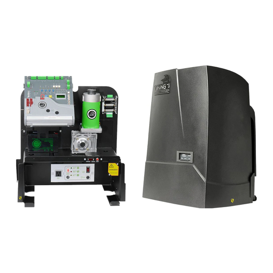
- Page 2 The L The L gate operator has the capacity to operate slide gates up gate operator has the capacity to operate slide gates up to 1 00 lbs. and 0 ft. in length at 100 duty cycle under extreme conditions. This efficient operator provides a solution for high traffic commercial slide gate applications. The Viking L gate operator offers efficiency and technology combined in a single package. THE VIKING L-3™ SLIDE GATE OPERATOR...
- Page 3 L-3 Vehicular Gate Operator • Revision L3NXMN10.A • November 2012...
-
Page 4: Parts Diagram/Parts List
PARTS DIAGRAM: Item Description Part No. Chassis VNXL3CH Chassis Battery Bracket VNXCHBBRK Gear Box VNXL3GB Motor VNXL3MO Electronic Positioning Sensor (EPS) VNXL3EPS 40B17 Sprocket VAL3SP17 Idler Pulley DSIP10 Idler Bushing (w/hardware) DSIB10 Battery Switch DUMRS10 Alarm DUAL10 Alarm Reset Switch VNXDUARS Manual Release Switch DUMRS10... -
Page 5: Operator References
OPERATOR REFERENCES: 1. OPERATOR COVER 10. GEARBOX 2. COVER LOCK 11. MANUAL RELEASE/MOTOR Switch discontinues power to the motor and allows for 3. ACCESS DOOR manual operation of gate external access to the Manual Release Switch and Alarm Reset Button 12. -
Page 6: Control Board References
CONTROL BOARD REFERENCES: 1. POWER HARNESS CONNECTOR 11. “MAGNETIC LOCK” Status LED 21. “DIAGNOSE” Button provides power to the control board. status of this on-board relay. pg 41 allows you to navigate through the pg 18-19 12. “MAGNETIC LOCK” Terminal Block 22. -
Page 7: Table Of Contents
TABLE OF CONTENTS: PARTS DIAGRAM/PARTS LIST PARTS DIAGRAM/PARTS LIST OPERATOR REFERENCES OPERATOR REFERENCES CONTROL BOARD REFERENCES CONTROL BOARD REFERENCES IMPORTANT SAFETY INFORMATION IMPORTANT SAFETY INFORMATION 6-12 6-12 Important Safety Instructions Important Installation Instructions Maintenance General Safety Precautions Operator Classification Photo Beam (non-contact sensor) Installation Edge Sensor (contact sensor) Installation Manual Release Audible Alarm Reset Installation... -
Page 8: Important Safety Information
IMPORTANT SAFETY INFORMATION WARNING! Not Following these instructions may cause severe injury or death. IMPORTANT SAFETY INSTRUCTIONS WARNING! To reduce the risk of severe injury or death. READ AND FOLLOW ALL INSTRUCTIONS . 2. Never let children operate or play with gate controls. Keep the remote away from children. -
Page 9: Important Installation Instructions
IMPORTANT SAFETY INFORMATION WARNING! Not Following these instructions may cause severe injury or death. IMPORTANT INSTALLATION INSTRUCTIONS (Continued) 6. Controls intended for user activation must be located at least six feet (6’) away from any moving part of the gate and where the user is prevented from reaching over, under, around or through the gate to operate the controls. -
Page 10: Maintenance
IMPORTANT SAFETY INFORMATION WARNING! Not Following these instructions may cause severe injury or death. MAINTENANCE Remove the Power Harness from the Control Board (refer to page 15) • Clean and lubricate the turning pins and gate hinges using the recommended lubricant. • Check that all mounting hardware of the gate operator is properly tighten. • Ensure that the gate moves freely. • Check for corroded parts and replace if necessary. • Check the battery for the following: - Battery connections must be free of corrosion. - Battery voltage must be 26v DC (fully charged battery). -
Page 11: Operator Classification
IMPORTANT SAFETY INFORMATION CAUTION: To Reduce the Risk of Fire or Injury to Persons: a. Use only the following type and size battery(ies): Yuasa NP7-12 b. Do not dispose of the battery(ies) in fire. The cells may explode. Check with local codes for possible disposal instructions. c. Do not open or mutalate the battery(ies). Released electrolyte is corrosive and may cause damage to the eyes or skin. -
Page 12: Photo Beam (Non-Contact Sensor) Installation
IMPORTANT SAFETY INFORMATION WARNING! Not Following these instructions may cause severe injury or death. NOTE: This type on installation DOES NOT reverse the gate all the way back to its limits when the photo beam is obstructed. This installation is only to protect against entrapment and to comply with UL325. -
Page 13: Edge Sensor (Contact Sensor) Installation
IMPORTANT SAFETY INFORMATION WARNING! Not Following these instructions may cause severe injury or death. NOTE: This type on installation DOES NOT reverse the gate all the way back to its limits when the edge sensor is obstructed. This installation is only to protect against entrapment and to comply with UL325. -
Page 14: Audible Alarm Reset Installation
IMPORTANT SAFETY INFORMATION WARNING! Not Following these instructions may cause severe injury or death. Audible Alarm Reset Switch Installation Manual Reset for the Audible Alarm • UL325 standard requires an audible alarm to go off after two consecutive events detected by the primary entrapment protection of the gate operator (obstruction sensor). -
Page 15: Important Installation Information
IMPORTANT INSTALLATION INFORMATION CAUTION: To Reduce the Risk of Fire or Injury to Persons: WARNING: For use with gates at a maximum 1600 lbs. in weight or 60 ft. in length. DO NOT allow pedestrian use of this gate DO NOT install the gate operator to lift gates Locate Control Buttons: 1. -
Page 16: Gate Operator Installation
Follow the local building code to determine the required depth of the con- crete pad. 2. Pad measurements recommended by Viking Access Systems are at lease 24” long, 18” wide and 24” deep to ensure the stable operation of the op- erator, and a minimum of 4”... -
Page 17: Post Mounting Option
GATE OPERATOR INSTALLATION Post Mounting Option TIP: The operator is equipped for post mount applications and is ready for installation. You will only need to supply the posts and u-bolts. Consult the local building codes for the depth and concrete requirements. 2. -
Page 18: Operator Positioning
GATE OPERATOR INSTALLATION Operator Positioning IMPORTANT: All openings of a horizontal slide gate are guarded or screened from the bot- tom of the gate to a minimum of 4 feet (1.22 m) above the ground to prevent a 2-1/2 inch (57.2 mm) diameter sphere from passing through the openings anywhere in the gate, and in that portion of the adjacent fence that the gate covers in the open position. - Page 19 GATE OPERATOR INSTALLATION ! TECHNICAL TIP: Before starting the installation procedure; • Open and close the gate manually, making sure there is sufficient space between the gate and adjacent walls. • Check that the wheels are turning freely on the track and there are no restrictions while pushing the gate to the open and closed positions.
-
Page 20: Electrical Installation
ELECTRICAL INSTALLATION High Voltage Supply Option ! Caution: Always turn off power breakers when working with high voltage. DO NOT connect the “Power Harness” to the Control Board until the electrical installation is complete and ready for verification. STEP 1 At the “Power Box”: a. -
Page 21: Low Voltage Supply Option
ELECTRICAL INSTALLATION Low Voltage Supply Option TIP: The operator is equipped with a Modular Power Box that can be relocated to provide power for low voltage installations. Supplies 24v AC to the operator. ! Caution: Always turn off power breakers when working with high voltage. DO NOT connect the “Power Harness”... -
Page 22: Limits Setup
LIMITS SETUP ! IMPORTANT: In the event of a complete power failure, including battery backup, the limits positions will have been cleared and will need to be reset by following the steps below.. STEP 1 Connect the Motor Harness to the: “OPEN LEFT”... - Page 23 LIMITS SETUP ! NOTE: The 1st cycle after the limit setup is the “Learn Cycles”. Allow a complete cycle to confirm your settings. 2. During the initial limit setup, the operator will run at half speed. To Readjust the Open Limit: To Readjust the Close Limit: Clear the current limit setting by Clear the current limit setting by...
-
Page 24: Master/Slave Setup
MASTER/SLAVE SETUP Two Wire Communication ! IMPORTANT: DO NOT run the Master/Slave communication cable in the same conduit or within 12” of 115 - 230v power supply cables. ! Technical Tip: DO NOT set the “Timer” and/or “Overlap” features on both operators Control Boards. -
Page 25: Wireless Communication (Bluetooth) Option
MASTER/SLAVE SETUP Wireless Communication (Bluetooth) Option ! Technical Tip: DO NOT set the “Timer” and/or “Overlap” features on both operators Control Boards. Only turn these features on at the Master Control Board. REQUIRED ADD-ON: 1. Viking Blue - Wireless Master/Slave Kit PART# VA-BLUE-MSKT Connect one Bluetooth Module, provided with VA-BLUE-MSKT, to the “V-Blue”... -
Page 26: Control Board Setup
CONTROL BOARD SETUP Initial Settings “Timer” “Overlap” Hold Open Timer Overlap Delay Automatically closes the gate after Delays the gate from closing for the the selected amount of time from 1-60 selected amount of time from 1-6 seconds. seconds. Turning the dial to between “0” and Typically not used on slide gates. -
Page 27: Initial Settings
CONTROL BOARD SETUP Initial Settings NOTE: Installing a jumper or jumper on the pins will activate the feature. “Auto Open” - Power Failure Option Opens the gate automatically during power failure. Resumes normal operation when power is restored. “Last Open” - Power Failure Option Will open the gate automatically when batteries critically low. -
Page 28: Obstruction Detection Sensor (Primary Entrapment Protection)
CONTROL BOARD SETUP Obstruction Sensor (Primary Entrapment Protection) ! IMPORTANT: The appropriate “ODS” setting is dependant upon the gate installation and construction. Set this feature accordingly. Additional Safety equipment should be used to reduce possible risk of injury or vehicle damage. “ODS”... -
Page 29: Accessory Connections
ACCESSORY CONNECTIONS Re-Open Photo Beam (vehicular Safety) NOTE: This type of photo-beam installation will stop then RE-OPENS the gate all the way to the open limit when the an beam is obstructed. Intended for vehicular safety ONLY. For the purpose of pedestrian entrapment, see pages 10-11. N.O. -
Page 30: Radio Receiver (Typical)
ACCESSORY CONNECTIONS Radio Receiver (Typical) ! IMPORTANT: The Hold Open “Timer” setting (page 24) effects how the gate will respond to the radio receiver command. The control board provides two modes of operation that a radio receiver can control the gate: Open-Stop-Close 1. -
Page 31: Anti-Tail Gate, Open Commands, Guard Station
ACCESSORY CONNECTIONS Anti-Tail Gate, Open Commands & Guard Station TECHNICAL TIP: For more information regarding accessory connections and terminal functions, refer to “Appendix (A)” on pages 40-41. Open Commands “Exit ”, “Fire” and “Strike” input terminals all provide an open command to the control board. -
Page 32: Viking Loop Rack
ACCESSORY CONNECTIONS Viking Loop Rack TIP: This operator may be equipped with a pre-wired Loop Rack that plug-in type loop detectors can be connected to. This provides a convenient alternative to the box type loop detectors that would need to be wired to the control board. Viking does not provide either type of loop detectors. -
Page 33: Guidelines For Loop Installations
ACCESSORY CONNECTIONS Guidelines for Loop Installation 1. Prevent sharp corners in the geometry of the loop sensor. 2. Install the appropriate number of turns for your loop geometry based on the loop perimeter. Use Table C (below) as a guide. 3. -
Page 34: Magnetic Lock, Lock Solenoid
ACCESSORY CONNECTIONS Magnetic Lock, Lock Solenoid NOTE: Viking Access Systems does not provided the these external gate lock devices and access control. These items can be purchases from your dealer or distributor. Power Do not use the 24v DC power supplied by the control board. -
Page 35: Barrier Arm (B-12) Synchronization Option
SYNCHRONIZATION WITH B-12 Barrier Arm (B-12) Synchronization Option NOTE: The Control Board provides a convenient solution for applications that require synchronized operation with the Viking Barrier Arm Operator model B-12. This type of application opens and closes in the follow pattern: 1. -
Page 36: Troubleshooting
TROUBLESHOOTING LED References In addition to the LCD Display, the control board LEDs monitor the various circuits of the control board. Use the table below to identify the corresponding “TS Ref#” and refer to page 36-39 for further troubleshooting. Page 39 # LED Status Meaning... - Page 37 TROUBLESHOOTING LED References Page 39 # LED Status Meaning TS Ref#(s) “AC VOLTAGE INPUT” SOLID Normal Condition. Incoming power to Modular Power Box is not sufficient.(page 18). 10 “PROTECTION WORKING” SOLID Normal Condition. EMI Board is damaged and circuit is not protected . Replace EMI Board. “AC VOLTAGE OUTPUT” SOLID Normal Condition.
-
Page 38: Lcd Display References
TROUBLESHOOTING LCD Display References The control board is equipped with a LCD Display that provides operator information, current conditions, settings, diagnostics and error messages. Use the table below to identify the corresponding “TS Ref#” and refer to page 39 for further troubleshooting. 1. - Page 39 TROUBLESHOOTING LCD Display References Page 39 Meaning LCD MSG TS Ref #s Multi meter displays MOT AMP This is the motor current amperage during operation x.x A MOT VOLT This is the actual motor voltage during operation xx.x VDC AC VOLT This is the actual power supply AC Voltage form the toroid transformer xx.x VAC CHARGE...
- Page 40 TROUBLESHOOTING LCD Display References Page 39 Meaning LCD MSG TS Ref #s ERR BAT 1, 2, 3, The battery is low The EPS (Electronic Position Sensor) has one of the following conditions: ERR EPS2 a) The EPS is not properly adjusted b) The EPS has a potential connection WRONG problem c) The EPS has the wrong cable harness ERR EPS2...
-
Page 41: Solutions
TROUBLESHOOTING Solutions Begin the troubleshooting process by referring to the error messages on the LCD Display and/or the Status LEDs on the control board. Use pages 34-38 to identify the Troubleshooting Reference # (TS Ref#) then reference the table below. TS Ref# CHECK Page Ref# Check that there high voltage power supplied to “J-Box”... -
Page 42: Appendix A, B & C
Appendix (A) Access Control Connections Power Connections The control board provides a 24v DC output to power external devices and controls. Alternatively, for devices that require a power supply other than 24v DC , the operators Power Box contains a convenient 120v AC receptacle to connect a plug-in transformer. - Page 43 APPENDIX (A) Relays In General NOTE: Viking Access Systems does not provided the external safety devices and access controls. These items can be purchases from your dealer or distributor. In General Glossary of Terms 1. Terminal: Wire Connections. In regards to the Viking control board, 2.
- Page 44 Appendix (B) Common Radio Receivers - Connections VIKING TECHNICAL SUPPORT 1.800.908.0884...
- Page 45 One low voltage, low current loop detector c. One low voltage, low current photo beam If more specific information is needed please consult with Viking Access Systems. For more information regarding solar energy refer to www.nrel.gov/solar VIKING TECHNICAL SUPPORT 1.800.908.0884...
-
Page 46: Viking Expansion Products
VIKING EXPANSION PRODUCTS Viking Bluetooth Master/Slave kit Secure and reliable wireless Master/Slave communication using Vikings bluetooth technology Part# VA-BLUE-MSKT Viking Bluetooth Diagnostic Tool Provides wireless diagnostic information while within range of the control board. Part# VA-BLUE VIKING RF-Link Wireless Master/Slave communication using a robust bidirectional radio signal. - Page 47 OUR CONTINUOUS COMMITMENT TO EXCELLENCE Viking Access ystems is continuously working hard to identify and design products that will appeal to the industry and it s needs. As technology continues to advance, we have developed a completely efficient and intelligent line of gate operators to meet the changing demands. These machines offer full L 2 and L 1 compliance, soft start and soft stop, intelligent obstruction sensors, continuous...
- Page 48 STANDARD FEATURES AND OPERATOR SPECIFICATIONS • L 2 and L 1 Compliant by nderwriter • Intelligent speed control with smooth start Laboratories ( L) standards. and stop, self ad ust system • Externally accessible Manual elease witch • Anti Tailgating and Operation Pre arming features • Fail afe option sets the gate to automatically transfer to a fail safe mode • On Board LCD Display provides diagnostics, in the event of a power failure, allowing the operator status, settings and real time volt gate to be pushed open without the use of and amp readings special knowledge of the equipment • Intelligent obstruction detection with • Fail ecure option sets the gate to ad ustable sensitivity electronically lock in the event of a power • Built in climate control for cold weather...
Need help?
Do you have a question about the L-3 and is the answer not in the manual?
Questions and answers
I have two vacuums L3 both have gray boards with black stickers. One has a VK on it for my wireless device. The other has v blue. How can I sync them together? I’m using the Viking connect black controller with wirelessly with a green light.
To sync two Viking L-3 operators using the Viking Konnect black controller (PART# VA-KONNECT-MS):
1. Plug the provided modules into the “V.K” plug & play connection on each operator’s control board.
2. It does not matter which module is on the master or slave board; the system will function regardless.
3. Ensure only the Master Control Board has the “Timer” and/or “Overlap” features enabled—do not enable these on both boards.
4. Verify that the green LEDs on both modules are illuminated solid, indicating active communication.
This completes the wireless Master/Slave setup using the Viking Konnect system.
This answer is automatically generated