Table of Contents
Advertisement
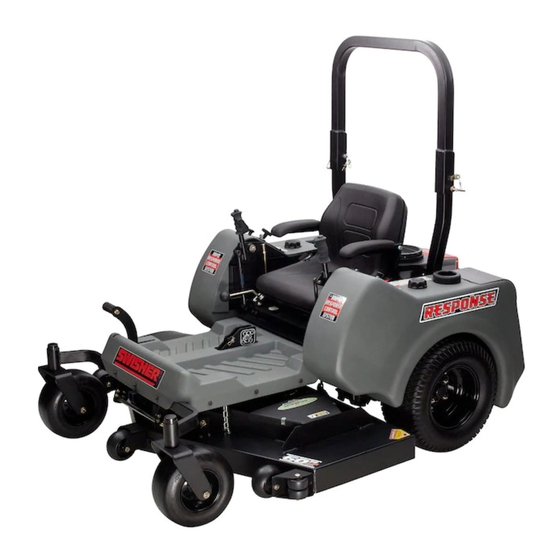
ZTR2760BS, ZTR2760BS-CA, ZTR2460BS, ZTR2460BS-CA,
ZTR2460KA, ZTR2460KA-CA
27 or 24 HP (Briggs & Stratton), 24 HP (Kawasaki) – 60" Wide Cut
Patent Pending
1602 CORPORATE DRIVE, WARRENSBURG MISSOURI 64093
PHONE: 660-747-8183 FAX: 660-747-8650
TOLL FREE: 1-800-222-8183
Manufacturing quality lawn care equipment since 1945,
Celebrating over 65 years of innovation
OWNER'S MANUAL
STARTING SERIAL # L112-352001
18870 REV 12-352
Advertisement
Table of Contents


Need help?
Do you have a question about the ZTR2760BS and is the answer not in the manual?
Questions and answers
How to change the oil in my ZTR2460KA