Table of Contents
Advertisement
Advertisement
Table of Contents

Summary of Contents for Swisher ZT2560
-
Page 1: Repair Manual
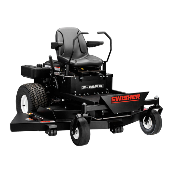
REPAIR MANUAL ZT2560 Swisher Mower Co Warrensburg, MO... -
Page 2: Table Of Contents
If engine won’t crank If engine won’t crank – continued If engine cranks but won’t start If PTO clutch will not engage Wire identification at switches Wire identification at switches – continued Drive control adjustment Drive control adjustment – continued Electrical components 10. -
Page 3: If Engine Won't Crank
IF ENGINE WON’T CRANK ALWAYS CHECK FUSE FIRST TEST #1 Using a remote starter switch or suitable device, make a connection between the large terminals on the solenoid. If engine does not crank!!! •Battery may be weak or dead •Starter may be bad •Battery cables may have bad connections •Do not go to Test #2 until this test gives results TEST #2... - Page 4 A neutral switch is located on the lower end of both drive control handles and is activated when the handles are outward in the neutral position. Check that the plunger buttons on both switches are depressed at least 3/8”. Meter should go to zero when checking continuity across switch terminals with plungers depressed.
-
Page 5: If Engine Cranks But Won't Start
ENGINE CRANKS BUT WON’T START Checks for electrical problems •While turning ignition switch to its first position, listen for the fuel solenoid on the carburetor to click. It must click to supply fuel to the carburetor. •Try a new spark plug. •Check for spark at plug when it is removed and the threaded end is grounded. -
Page 6: If Pto Clutch Will Not Engage
IF PTO CLUTCH WILL NOT ENGAGE Apply a negative ground to this terminal Apply 12 volts to this terminal. Clutch should activate, if it doesn’t, clutch is defective. If clutch checks OK, use a voltmeter to measure if there is 12 volts at the brown wire’s terminal. First turn ignition switch to the ON position but don’t start the engine. -
Page 7: Wire Identification At Switches
WIRE IDENTIFICATION AT SWITCHES 3623 IGNITION SWITCH One gray wire goes to the PTO switch and the other goes to the hour meter One black wire goes to PTO switch and the other goes to the engine plug Green wire goes to neutral switches and on to the ignition switch. -
Page 8: Wiring Harness To Engine Plug Connection
WIRING HARNESS TO ENGINE PLUG CONNECTION WIRING HARNESS PLUG TO ENGINE Gray wire goes to hour meter Green wire goes to hour meter Gray wire goes to carburetor fuel solenoid Green wire goes to oil pressure switch Black wire goes to engine ignition module Red wire goes to engine charging system Green wire goes to hour meter Red wire goes to terminal on solenoid... -
Page 9: Carburetor Fuel Solenoid
BATTERY CHARGING SYSTEM Voltage Regulator CARBURETOR FUEL SOLENOID Black wire goes to engine ground. Gray wire goes to the engine plug, then on to the ignition switch where it receives power to activate the fuel shut off valve. Fuel shut off solenoid is a Briggs part and is available through them only. -
Page 10: Drive Control Adjustment
DRIVE CONTROL ADJUSTMENTS Control plate shown in neutral position Hydro linkage LEFT SIDE SHOWN Start your adjustments by putting the drive control arms in the neutral position. Remove the linkage from the control plate at the Eaton hydro by removing the cotter pin and washer on the under side. - Page 11 DRIVE CONTROL ADJUSTMENTS (CONTINUED) LEFT SIDE SHOWN Once both hydro units are pulling equally, make your final control handle adjustment with this ball linkage. Whichever handle is going the farther forward, lengthen the linkage on that side until the handles are straight across when mower is traveling in a straight line.
-
Page 12: Parking Brake And Neutral Switch Operation
PARKING BRAKE AND NEUTRAL SWITCH OPERATION Right side drive control handle. Parking brake cable attaches here. Right side is shown. Control panel has been removed for better view. Parking brake is activated by this bolt as the drive control handle is swung outward in the neutral position. -
Page 13: Deck Lifting System
DECK LIFTING SYSTEM Three rocker arms are activated by the deck lift handle. This is the right side control. Note the routing of the cable. It drops straight below to the deck. This center rocker arm lifts the front center of the deck. It also drops through the lower frame but is directed by two pulleys under the mower frame to the front of the deck. -
Page 14: Deck Belt Replacement
DECK BELT REPLACEMENT Tension on belt can be adjusted by tightening or loosening this nut. ENGINE TO DECK BELT •Lower the deck to lowest setting •Loosen tension on tension idler •Remove worn or damaged belt •Using part# 10263 belt, route it around the engine pulley as shown in the diagram. -
Page 15: Repairing Or Replacing Blade Driver
REPAIRING OR REPLACING BLADE DRIVER Torque top nut to 90 ft/lbs Replacing this nut each time is recommended. Machine washers are used to keep the pulley from contacting the outer race of the bearing. When applying torque to the top nut the pressure is to the inner race only and onto the shank on the inner... -
Page 16: Replacement Parts
For additional assistance on service Contact Swisher Mower Co., Inc. Phone 1-800-222-8183 Fax 1-660-747-3160 E-mail cust.serv@swisherinc.com...


Need help?
Do you have a question about the ZT2560 and is the answer not in the manual?
Questions and answers