Table of Contents
Advertisement
TEC2101-3 N2 Networked Single-Stage Thermostat
Installation Instructions
Applications
The TEC2101-3 Thermostat is an N2 networked device
that provides control of single-stage heating/cooling
equipment. The technologically advanced TEC2101-3
Thermostat features a Building Automation System
(BAS) N2 Bus communication capability that enables
remote monitoring and programmability for efficient
space temperature control.
IMPORTANT: The TEC2101-3 Thermostat is
intended to provide an input to equipment under
normal operating conditions. Where failure or
malfunction of the thermostat could lead to personal
injury or property damage to the controlled
equipment or other property, additional precautions
must be designed into the control system.
Incorporate and maintain other devices such as
supervisory or alarm systems or safety or limit
controls intended to warn of, or protect against,
failure or malfunction of the thermostat.
North American Emissions Compliance
United States
This equipment has been tested and found to comply
with the limits for a Class A digital device pursuant to
Part 15 of the FCC Rules. These limits are designed to
provide reasonable protection against harmful
interference when this equipment is operated in a
commercial environment. This equipment generates,
uses, and can radiate radio frequency energy and, if
not installed and used in accordance with the
instruction manual, may cause harmful interference to
radio communications. Operation of this equipment in a
residential area is likely to cause harmful interference,
in which case the user is required to correct the
interference at his/her own expense.
TEC2101-3 N2 Networked Single-Stage Thermostat Installation Instructions
Part No. 24-9890-420, Rev. —
Canada
This Class (A) digital apparatus meets all the
requirements of the Canadian Interference-Causing
Equipment Regulations.
Cet appareil numérique de la Classe (A) respecte
toutes les exigences du Règlement sur le matériel
brouilleur du Canada.
Installation
Location Considerations
Locate the TEC2101-3 Thermostat:
•
on a partitioning wall, approximately 5 ft (1.5 m)
above the floor in a location of average
temperature
•
away from direct sunlight, radiant heat, outside
walls, behind doors, air discharge grills, stairwells,
or outside doors
•
away from steam or water pipes, warm air stacks,
unconditioned areas (not heated or cooled), or
sources of electrical interference
Note: Allow for vertical air circulation to the
TEC2101-3 Thermostat.
Issued September 14, 2006
1
Advertisement
Table of Contents

Related Manuals for Johnson Controls TEC2101-3 N2


Summary of Contents for Johnson Controls TEC2101-3 N2
-
Page 1: Installation Instructions
Operation of this equipment in a residential area is likely to cause harmful interference, in which case the user is required to correct the interference at his/her own expense. TEC2101-3 N2 Networked Single-Stage Thermostat Installation Instructions... - Page 2 5. Align the thermostat mounting base on the wall and use the base as a template to mark the two mounting hole locations. Figure 4: Removing the Screw Terminal Blocks TEC2101-3 N2 Networked Single-Stage Thermostat Installation Instructions...
- Page 3 Room Air Sensor If using the same power source 24 VAC Sensor for the thermostat and heating loads, Thermostat Power install a jumper across RC and RH. Figure 5: Wiring the TEC2101-3 Thermostat TEC2101-3 N2 Networked Single-Stage Thermostat Installation Instructions...
-
Page 4: Connecting The N2 Bus
(Occupied Heating SP) ADI-4 N2 AO CSAD 54 to 100°F Cooling SP (12 to 37.5°C) (Occupied Cooling SP) ADI-5 N2 AO CSAD 40 to 90°F (4.5 to 32°C) Setback Heating SP (Unoccupied Heating SP) TEC2101-3 N2 Networked Single-Stage Thermostat Installation Instructions... - Page 5 The BAS Model Point type is the N2 Bus Objects listed in Table 1 controls the definition inside the model file. Use an NCM CS object thermostat. to retrieve the data. TEC2101-3 N2 Networked Single-Stage Thermostat Installation Instructions...
-
Page 6: Setup And Adjustments
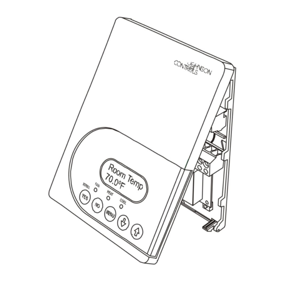
Room Temp Backlit, plain text 70.0ºF LCD is easy to read LEDs indicate in any condition. system activity. Five keys on the thermostat make operation easy and intuitive. Figure 6: Front Cover of Thermostat TEC2101-3 N2 Networked Single-Stage Thermostat Installation Instructions... - Page 7 Status Display Menu and when the through the following parameters: message is displayed, the backlight momentarily • Room Temperature lights up. • System Mode Both inputs can be configured to the Selection Options included in Table 2. TEC2101-3 N2 Networked Single-Stage Thermostat Installation Instructions...
- Page 8 (fan, heating, or cooling) is authorized. Also can be used to sequence the startup of multiple units in one location. Default: 10.0 sec TEC2101-3 N2 Networked Single-Stage Thermostat Installation Instructions...
- Page 9 The fan delay is only active when the fan is in the Auto mode. Com addr N2 network address at the Range: 1 to 255 thermostat; coincides with the address assigned at the supervisory controller. Default: 4 TEC2101-3 N2 Networked Single-Stage Thermostat Installation Instructions...
- Page 10 When adjusting the temperature, press the UP or DOWN arrow key to change the value in 0.5F°/0.5C° increments; press and hold the UP or DOWN arrow key to change the value in 5.0F°/5.0C° increments. TEC2101-3 N2 Networked Single-Stage Thermostat Installation Instructions...
-
Page 11: Operation
1. Press the NO key to all prompts until the Cancel the NO key to advance to the set? Y/N ovrd Y/N prompt appears. If the thermostat is in the unoccupied heating setpoint. unoccupied override state, this is the first prompt. TEC2101-3 N2 Networked Single-Stage Thermostat Installation Instructions... -
Page 12: Selecting The System Mode
3. Press the YES key to return to the Status Display and press the YES key to exit the Main User Menu. Menu or press the NO key to return to the fan mode selection menu. TEC2101-3 N2 Networked Single-Stage Thermostat Installation Instructions... -
Page 13: Repair Information
TE-6361M-1 Outdoor Air Temperature Sensor TE-6363P-1 Additional TE-636xx-x Series 10k ohm Johnson Controls Type II Thermistor Sensors are available; refer to the TE-6300 Series Temperature Sensors Product Bulletin (LIT-216320) for more details. Repair Information If the TEC2101-3 Thermostat fails to operate within its specifications, see Table 5 for troubleshooting details and Table 6 for alarm messaging. -
Page 14: Technical Specifications
The performance specifications are nominal and conform to acceptable industry standards. For application at conditions beyond these specifications, consult the local Johnson Controls office. Johnson Controls, Inc. shall not be liable for damages resulting from misapplication or misuse of its products.
Need help?
Do you have a question about the TEC2101-3 N2 and is the answer not in the manual?
Questions and answers