Table of Contents
Advertisement
Advertisement
Table of Contents

Related Manuals for Kathrein MSK 200/S2


Summary of Contents for Kathrein MSK 200/S2
- Page 1 User Manual Antenna signal meter system MSK 200/S2...
-
Page 2: Preface/Important Notes
PREFACE/IMPORTANT NOTES Dear customer, We kindly ask you to observe all instructions contained in this manual. The Kathrein-Werke KG has made every effort to ensure that the data and descriptions in this manual are accurate and complete. We reserve the right to make changes to this manual without prior notice. This particularly applies to modifi - cations required for technical improvement. -
Page 3: Table Of Contents
PREFACE/IMPORTANT NOTES GENERAL SAFETY INFORMATION ... 3 CONTENT ... 4 SAFETY FEATURES/DELIVERY SCOPE ... 6 DELIVERY SCOPE ... 7 OPERATION ... 7 INITIAL START-UP ... 7 SETTING UP THE DEVICE ... 7 SET-UP OPTIONS USING THE DEVICE ON THE SHOULDER STRAP ... -
Page 4: Safety
Symbols used on Kathrein devices and in manuals: Follow operating instructions Information on the weight of devices with a mass > 18 kg Earth conductor connection. - Page 5 5. Prior to switching on the device, ensure that the nominal mains voltage set on the device and the nominal mains voltage of the supply match. If it is necessary to change the voltage setting, it may also be necessary to change the respective mains fuse for the device. 6.
-
Page 6: Features/Delivery Scope
fi nal measurements on antenna and distribution systems. DELIVERY SCOPE MSK 200/S2, Order no. 21710024 (75 Ω): - 1 antenna signal meter system MSK 200 - 1 AC power supply unit... -
Page 7: Operation
INITIAL START-UP Prior to operating for the fi rst time, please take the T 8.0 A fuse out of the packaging and fi t it into the provided fuse holder. After insertion of the protector, the device muss be operated or charged on the power supply unit for ap- proximately two hours. -
Page 8: Using The Device On The Shoulder Strap
USING THE DEVICE ON THE SHOULDER STRAP When the device is used on the strap, also provide for adequate ventilation! To avoid a build up of heat, the openings for the fan and the ventilation holes must always be clear. For right-handed users Pass the shoulder strap over your right shoulder! Strap fastener... -
Page 9: General Operation
THE HELP FUNCTION The MSK 200‘s help function follows a new concept. All help fi les have been saved in the MSK 200 and can be called up whenever required. All you have to do to call up the help menu is to press the -key at any time when operating the MSK 200. -
Page 10: Touchscreen Operation
SECOND FUNCTION of touchscreen HELP TOUCHSCREEN OPERATION SOURCES Measurement Selection Selection (SOURCE) (ANALYZE) GENERAL OPERATION Tap on the touchscreen keys to select the respective task! This type of key opens a further menu! When the “SOURCE“ button is pressed, the source selection buttons appear, which can be used to select the signal path! When the “ANALYZE”... - Page 11 GENERAL OPERATION This type of key leads to a selection of various set- tings (e.g. selection of the channel)! This type of key offers the facility for alphanumerical input (e.g.: entering programme names)! This type of key offers the facility for numerical input (e.g.: entering programme numbers) Tap on the screen to set the markers directly or to shift them!
- Page 12 This type of key indicates an option that is unavailable on this unit! This type of key indicates a defective function in the unit! Tap on this type of key to switch between two operating modes (e.g.: 22 kHz signal ON/ OFF)! Press this key e.g.
-
Page 13: Operation
CHOICE OF THE SIGNAL SOURCE AND MEASUREMENT The most important keys on the MSK 200 are After activating the key, you will be able to defi ne the source and the channel or transponder to be measured. After pressing the have this carried out. -
Page 14: Choosing The Channel To Be Measured
CHOOSING THE CHANNEL TO BE MEASURED Now one can choose the channel to be measured: Generally there are different possibilities offered as to how a measurement channel can be chosen Selection of programme through programme name 1.1. Press “Chan.Tab“ to select the desired channel table 1.2. - Page 15 Information on the individual measurement possibilities can also be found in the on-board help menus. Generally an optimal pre-setting of parameters is saved in the MSK 200 for each type of measurement. There are though many other set-up possibilities that can be carried out dependant on the measurement in question.
-
Page 16: Function Overview
OPERATION Mains Battery external battery supply OPERATION keyboard external keyboard Touch REMOTE CONTROL Ethernet RS232 PCMCIA-Module analogue modem VIDEO DISPLAY Analogue video TV-CATV FTA digital video DVB-C J83 B Scrambled digital DVB-C video J83 B CI/CA SIGNALLING Display operational mode/ standby (using ON/OFF button) LNB supply... -
Page 17: Measurement Options
RECEPTION RANGES TV (CATV/terrestrial) Satellite Spectrum analysis DEMODULATION Digital J83 A/C (DVB-C) 16, 32, 64, CATV 128 ,256 QAM Analogue PAL, NICAM CATV B/G, I, D/K, L/L´, M/N Digital- COFDM (DVB-T) 2k, 8k; terrestrial 4, 16, 64 QAM; 6,7,8 MHz Analogue- PAL, NICAM terrestrial... -
Page 18: Technical Appendix
DESIGN • Manageable portable signal meter • High-resolution 10.4“ TFT colour display to graph analogue and digital TV signals and graphics • Backlight - thus the display is excellently readable also in bright sunlight (typ. 600 cd/m • Easy operation using 12 hard keys and through the infrared touch screen for menu-dependant, user-con- trolled, intuitive operation (context-dependant help) •... - Page 19 Audio IF bandwidth Video output voltage/impedance Hum measurement S/N weighting (to CCIR Rec. 567) Analogue input S/N weighting (to CCIR Rec. 567) TECHNICAL APPENDIX MSK 200/S2 21710024 dBµV Max peak, min peak, auto peak, sample, RMS Picture/s dBµV Pixel /Ω...
- Page 20 Digital CATV receiver (J83 A, B, C) Modulation type Symbol frequency Frequency increment Video output voltage/impedance IF bandwidths MER measurement Digital terrestrial TV receiver (DVB-T, ATSC) Modulation type Symbol frequency Frequency increment Video output voltage/impedance IF bandwidths MER measurement Digital satellite receiver (DVB-S, DVB-S2) Modulation type Symbol frequency Frequency increment...
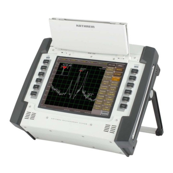
- Page 21 General Screen Touch Screen Temperature range Dimensions (W x H x D) Weight The illustration shows the MSK 200/S2 21710024 with 75-Ω-BNC socket; another version is available, MSK 200/S2 21710025 with 50-Ω-N socket. TECHNICAL APPENDIX Ω 1.6/5.6 (75) °C N-type socket (50)
-
Page 22: Service
DEVICE CALIBRATION The calibration interval is dependent on operational demands made on it and should be carried out every 1 to 2 years. The calibration can be carried out by ESC Kathrein customer service, see below. EXTERIOR CLEANING Clean the exterior of the device using a soft cloth, fl uff-free duster or a brush. In case of heavier soiling it is also possible to use alcohol or a mild soap solution. -
Page 23: Service
Fa. ESC Elektronik Service Chiemgau GmbH Bahnhofstr. 108 83224 Grassau E-Mail: service@esc-kathrein.de SERVICE If, despite studying this operating manual, you still have questions about getting started with the unit or using it correctly, or if unexpected problems occur, please contact your... - Page 24 Internet: http://www.kathrein.de KATHREIN-Werke KG • Anton-Kathrein-Straße 1 - 3 P.O. Box 10 04 44 • 83004 Rosenheim/GERMANY...
Need help?
Do you have a question about the MSK 200/S2 and is the answer not in the manual?
Questions and answers