Table of Contents
Advertisement
Quick Links
Advertisement
Table of Contents

Subscribe to Our Youtube Channel
Related Manuals for Kathrein MSK 200


Summary of Contents for Kathrein MSK 200
- Page 1 Manual Antenna measuring system MSK 200 Valid from software version V 3.8...
-
Page 2: Foreword/Important Instructions
FOREWORD/IMPORTANT INSTRUCTIONS Dear customer, please follow all the information given in this manual. KATHREIN-Werke KG has made every effort to ensure the information and descriptions are correct and complete. We reserve the right to make changes to this manual without prior notice. In particular, this applies to changes made due to technical advancements. -
Page 3: Table Of Contents
VARIANTS ........................22 MAINTENANCE ......................22 DEVICE CALIBRATION ......................22 OUTSIDE CLEANING ......................22 INTERIOR CLEANING ........................22 FUNCTION TEST ................... 22 REQUIRED MEASURING EQUIPMENT ..........................22 STORAGE ..........................23 SERVICE ......................23 CUSTOMER SERVICE ..................23 KATHREIN CUSTOMER HOTLINE... -
Page 4: Safety Instructions
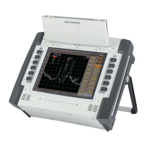
Read these instructions carefully before setting up the device. METER PROPERTIES/SCOPE OF SUPPLY The MSK 200 is a latest generation meter in a compact form which leaves nothing to be desired when it comes to testing antenna and cable systems, even including professional head-ends. The device is suitable for use in the lab and for monitoring head-ends with remote control, as well as for acceptance measurements on antenna and distribution systems. -
Page 5: Set Up
SET UP INITIAL SET UP Before operating the device for the fi rst time remove the T 8.0 A fuse from the packaging and place it in the fuse holder on the rear of the device. After fi tting the fuse, the device must be operated/charged for approx. two hours on the mains. Then the device must be operated on the battery and the battery fully discharged at least once (until the device switches itself off). -
Page 6: Using The Device On The Strap
SET UP USING THE DEVICE ON THE STRAP When the device is used on the strap, also pay attention to adequate ventilation of the device! To avoid a build up of heat, the openings for the fan and the ventilation holes must always be clear. For right-handers For left-handers Reach with the right hand through the belt and also... -
Page 7: Basic Information On Operation
BASIC INFORMATION ON OPERATION THE HELP FUNCTION The help function for the MSK 200 is very innovative. All the help fi les are always available as they have been saved in the MSK 200. To open this help, simply press the button. -
Page 8: Touchscreen Operation
BASIC INFORMATION ON OPERATION SECOND FUNCTION on the touch-screen HELP TOUCHSCREEN OPERATION Tap on the touchscreen buttons to select the respective task. This type of button opens a further menu. Sources Measurement If the “SOURCE” button is pressed, the source selection selection selection buttons appear, which can be used to... - Page 9 BASIC INFORMATION ON OPERATION This type of button leads to a selection of various settings (e.g. selection of a channel). This type of button enables letters and numbers to be entered (e.g. programme name entry). Using this button enter numbers (e.g.
- Page 10 BASIC INFORMATION ON OPERATION To open the zoom window, hold your fi nger longer on the marker; you can then shift it to the desired position. Press the “FUNCTION” button, tap on the screen and drag the section of the image using your fi nger (e.g.
-
Page 11: Operation
After pressing the button the required measurement can be selected and made. On the MSK 200's display the ANALYSE menu is always at the edge of the screen, the SOURCE menu beside it. -
Page 12: Selection Of The Channel To Be Measured
OPERATION SELECTION OF THE CHANNEL TO BE MEASURED Now the required measuring channel can be selected: In principle there are various ways you can select the channel Selection of a programme using the programme names 1.1. Select the required channel table using the “Chan.Tab” button. 1.2. - Page 13 You will also fi nd information on the different measuring methods in the onboard help. In the normal case, optimum parameter presettings are saved in the MSK 200 for each measurement. However, you can also make many settings to suit the related measurement. These are displayed on the related menu.
-
Page 14: Overview Of Functions
OVERVIEW OF FUNCTIONS OPERATION Mains External AC power unit 100...240 V Battery Internal Li-ion rechargeable battery 12 V/6.5 Ah External battery supply Vehicle 11 V...16 VDC OPERATION Keypad 12 hard keys On/Off, Help, Prog.+, Prog.-, Analyze, Source, OSD/Off, Vol.+, Vol.-, Copy, Function, Extend External keyboard ASCII keyboard (PS2) - Page 15 OVERVIEW OF FUNCTIONS RECEPTION RANGES TV (CATV/terrestrial) 5...900 MHz Satellite 900..3100 MHz Digital terrestrial 5...3080 MHz 87.5...108 MHz Spectrum analysis 5...3100 MHz DEMODULATION Digital J83 A/C (DVB-C) 16, 32, 64, J83 B DOCSIS CATV 128, 256 QAM 64 QAM 64, 256 QAM Analogue PAL, NICAM NTSC, NICAM...
-
Page 16: Technical Appendix
• MSK 200/M4 - 21710026 (75 Ohm) or 21710027 (50 Ohm): same as MSK 200/S2; plus MPEG-4 decoder for the display of HD pictures and HDMI interface • MSK 200/ME - 21710034 (75 Ohm) or 21710035 (50 Ohm): same as MSK 200/M4;... - Page 17 TECHNICAL APPENDIX Type MSK 200/S2 MSK 200/M4 MSK 200/ME MSK 200/MT 21710024 (75 Ω) 21710026 (75 Ω) 21710034 (75 Ω) 21710042 (75 Ω) Part no. 21710025 (50 Ω) 21710027 (50 Ω) 21710035 (50 Ω) 21710043 (50 Ω) Spectrum analyser Frequency range...
- Page 18 Channel bandwidths 6/7/8 Digital terrestrial TV reception (DVB-T, ATSC) Frequency range 10-3075 Modulation process 4QAM, 16 QAM, 64 QAM, 8 VSB, for MSK 200/MT plus 16 VSB Symbol rate According to standard Frequency increment Video output voltage/impedance Vpp/Ohm 1/75 ± 1 dB...
- Page 19 TECHNICAL APPENDIX Type MSK 200/S2 MSK 200/M4 MSK 200/ME MSK 200/MT 21710024 (75 Ω) 21710026 (75 Ω) 21710034 (75 Ω) 21710042 (75 Ω) Part no. 21710025 (50 Ω) 21710027 (50 Ω) 21710035 (50 Ω) 21710043 (50 Ω) Frequency increment MER measurement typ.
- Page 20 TECHNICAL APPENDIX Type MSK 200/S2 MSK 200/M4 MSK 200/ME MSK 200/MT 21710024 (75 Ω) 21710026 (75 Ω) 21710034 (75 Ω) 21710042 (75 Ω) Part no. 21710025 (50 Ω) 21710027 (50 Ω) 21710035 (50 Ω) 21710043 (50 Ω) Frequency accuracy TCXO...
- Page 21 TECHNICAL APPENDIX The fi gure shows the MSK 200/M4 21710026 with 75-Ω BNC socket. Depending on the version of the MSK 200, some of the connections shown here are optional.
-
Page 22: Maintenance
DEVICE CALIBRATION The calibration interval is dependent on use and operational demands, and should be between 1 and 2 years. Calibration can be done by Kathrein customer service, see next page. OUTSIDE CLEANING A soft cloth, lint-free duster or paint brush is recommended for cleaning the outside of the device. In case of heavier soiling it is also possible to use alcohol or a mild soap solution. -
Page 23: Service
35576 Wetzlar, Germany E-Mail: service-kathrein@esw-katek.de KATHREIN CUSTOMER HOTLINE If, despite studying this operating manual, you still have questions about getting started with the device or using it correctly, or if unexpected problems occur, please contact the Kathrein customer hotline. Tel: 08031/184-700... - Page 24 Internet: http://www.kathrein.de KATHREIN-Werke KG • Anton-Kathrein-Straße 1 - 3 P.O. Box 100 444 • 83004 Rosenheim • GERMANY...
Need help?
Do you have a question about the MSK 200 and is the answer not in the manual?
Questions and answers