Table of Contents
Advertisement
Quick Links
Advertisement
Table of Contents

Related Manuals for Kathrein MSK 140/OHD


Summary of Contents for Kathrein MSK 140/OHD
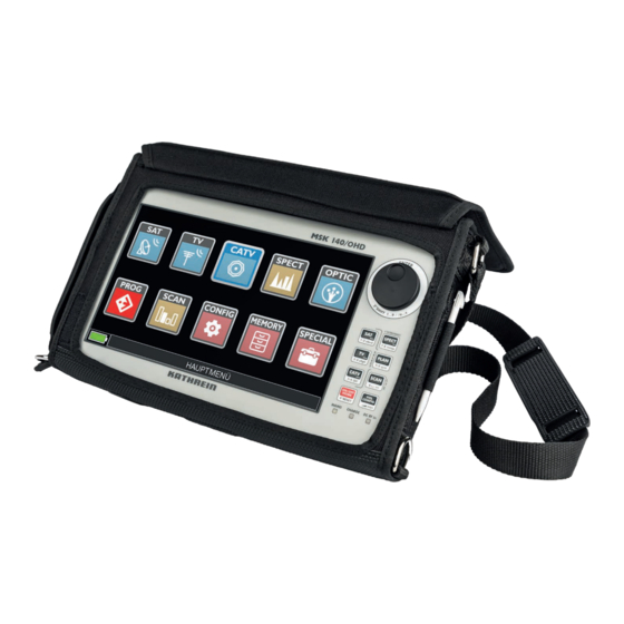
- Page 1 Instructions for use MSK 140/OHD Englisch...
-
Page 2: Table Of Contents
Contents Preface ................. 5 Validity of Manual ..............5 Intended Use ................ 5 Explanation of Symbols and Signal Words ......7 Symbols ......................7 Signal Words ...................... 7 Other Symbols ....................7 Presentation of Operating Instructions ............8 Safety Instructions ............... 8 Important Information on the Rechargeable Batteries .. - Page 3 Changing Basic Parameters ..........22 13.1 Changing the Volume ..................22 13.2 Changing the Brightness ................22 13.3 Displaying an Analogue Video Signal ............23 13.4 Changing the RF IN Setting ................23 13.5 Activating and Deactivating Power Saving Mode ........24 Configuration Menu ............
- Page 4 17.4.2 Opening the Data-logger ................... 60 17.4.3 Manual Memory Plan ..................60 17.4.4 File manager ...................... 62 Special Functions ............... 63 18.1 SAT Special Functions ..................63 18.1.1 SAT SCR ......................63 18.1.2 DiSEqC motor ....................64 18.1.3 SAT Finder ......................64 18.1.4 Tone and signal-to-noise ratio ................
-
Page 5: Preface
Preface Dear customer, Please follow all the information given in this manual. KATHREIN Digital Systems GmbH has made every effort to ensure the information and descriptions are correct and com- plete. We reserve the right to make changes to this manual without prior notice. In particular, this applies to changes made due to technical advancements. - Page 6 Intended Use Features: ● Level measurement of analogue and digital TV signals (DVB-S/S2/S2x, DVB-C, DVB-T/ T2, DAB/DAB+, TV, FM) including return path ● Video display of analogue and digital TV signals ● BER/MER measurement and display ● Constellation diagram display ●...
-
Page 7: Explanation Of Symbols And Signal Words
Explanation of Symbols and Signal Words Symbols General warning symbol Risk of material damage or malfunctions Signal Words Notice This signal word indicates a hazard which can lead to damage to property or malfunction. This signal word indicates useful tips and recommendations. Other Symbols Symbol Definition... -
Page 8: Presentation Of Operating Instructions
Safety Instructions Presentation of Operating Instructions The operating instructions in this document are shown either in the short form or the long form. Short form Step 1 ▶ step 2 ▶ step 3 ▶... Example: CONFIG ▶ CONFIGURATION MENU ▶ METER Long form Step 1 Example: 1. -
Page 9: Important Information On The Rechargeable Batteries
Important Information on the Rechargeable Batteries General information The supplied rechargeable battery is a lithium polymer battery of the highest quality. The battery life is 3 hours and depends on the following conditions: ● LNB power consumption: Single, dual or quad LNB. ●... -
Page 10: Transport And Storage
Transport and Storage Transport and Storage ► Transport and store the device in its original case. ► Protect the device against dust, dirt, moisture and direct sunlight. ► Transport and store the device only in the permitted temperature range between -25 and 70 °C. -
Page 11: Abbreviations And Technical Terms
Abbreviations and Technical Terms APID (Audio Packet Identifier) Audio reception parameters in the MPEG data stream aBER (Bit Error Rate after Viterbi) Ratio of transmitted bits to erroneous bits after Reed Solomon (Viterbi) (Bose Chaudhuri Hocquenghem) External error protection decoder (Bit Error Rate) The bit error rate is a measure of the quality of DVB sig- nals. - Page 12 Abbreviations and Technical Terms NsMargin (Noise Margin) Reserve of the signal to the noise level (up to the "fall of the cliff effect" with digital signals) Optical modulation index The Packet Error Ratio indicates the number of incompletely received data packets as a proportion of all transmitted packets (after Viterbi).
-
Page 13: Device Description
Device Description 11.1 Front view No. Name Function ① Touch-screen for display and operation ② Rotary wheel for navigation between menu items and to confirm the selec- tion ③ opens the measurement range of SAT signals ④ SPECT SCREEN- activates the spectrum analyser mode. SHOT screenshot function (saves to USB storage medium) ⑤... - Page 14 Device Description No. Name Function ⑪ MAINS/CHARGE/ LEDs go on when: DC RF in Signal meter is turned on or connected to the mains. The device is charging. A DC voltage component is present in the satellite signal. The signal meter is operated using the push-buttons -10), the rotary wheel ( ) and the touch-screen (...
-
Page 15: Top View
11.2 Top View No. Name Function ① Optical Connection for the optical 75 Ω F input connector; there is a special optical measuring interface in the main menu of the MSK 140 ② HF SAT/TV input connection for the SAT input plug 230 - 2600 MHz connection for the TV/CATV input plug 5 - 1250 MHz ③... -
Page 16: Operating The Signal Meter
Operating the Signal Meter ② HDMI output connection for an external monitor or TV The signal meter automatically detects an exter- nal screen and switches from the internal touch- screen to the external screen. ③ USB B port connection for PCs for software update and upload/download of data via the S.M.A.R.T. -
Page 17: Updating Firmware And Channel Plans
Updating Firmware and Channel Plans All information on updating firmware and channel plans using the S.M.A.R.T software can be found in the S.M.A.R.T. software manual at www.kathrein-ds.com 12.5 Resetting the Device to Factory Settings The signal meter is supplied with a default configuration (factory configuration) for the parameters for the system and plan/measurement. -
Page 18: Reading The Led Display
The signal meter cannot be unit is not powered on. 0.5 sec. off from Kathrein ► Check power supply unit. 0.5 sec. on ON/OFF yes or no The signal meter is turned on. HOME... -
Page 19: Touch Screen Display Areas
12.7 Touch Screen Display Areas ① Setting parameters and values ② Picture display ③ Context-sensitive menu ④ Transport stream information ⑤ Measurements The following functions can be accessed via the main menu on the touch- screen as well as via the push-buttons: ●... -
Page 20: Changing A Setting Value Using The Navigation Wheel And The Drop-Down Menu
Operating the Signal Meter 12.9 Changing a Setting Value Using the Navi- gation Wheel and the Drop-down Menu 1. Press the rotary wheel to activate the row with the set- ting parameters. ➯ A setting parameter is active (highlighted blue). 2. - Page 21 4. Enter the setting value using the numeric field at the bottom of the touch-screen or using the push-buttons. The cursor automatically jumps to the next input field. If you want to change the value in an input field, use the rotary wheel to navigate to this input field and enter the value again.
-
Page 22: Changing Basic Parameters
Changing Basic Parameters Changing Basic Parameters Using the volume menu, it is possible to change the following settings in the signal meter: ● ● VOLUME BATTERY SAVING ● ● BRIGHTNESS CONFIGURATION MENU ● VIDEO IN (video input) ● RF IN 13.1 Changing the Volume 1. -
Page 23: Displaying An Analogue Video Signal
➯ The brightness value is changed. The BRIGHTNESS parameter is active (high- lighted blue). To select other parameters and values, perform steps 1 – 6, see Helligkeit ändern. It is also possible to switch between volume menu parameters directly via the touch-screen. -
Page 24: Activating And Deactivating Power Saving Mode
Configuration Menu 13.5 Activating and Deactivating Power Saving Mode The default setting for BATTERY SAVING is OFF. In the setting, after 15 seconds of inactivity the screen brightness is automatically reduced, and after 5 minutes of inactivity the device switches off. 1. - Page 25 Name Function ① TIMER OFF determines whether or not the signal meter automatically switches off after a certain period of inactivity OFF/5 min/10 min/15 min/30 min ② UNIT measurement unit of the HF level that is displayed in the meas- urement interface dBm/dBµV/dBmV ③...
- Page 26 Configuration Menu ⑦ CALIBRATE touch-screen calibration function TOUCH- 1. Tap CALIBRATE TOUCHSCREEN or press with the rotary SCREEN wheel. ➯ A black screen with the action prompt and the cursor in the upper left corner appears: 2. Tap on the cursor. ➯...
- Page 27 ⑨ LAN CONFIGU- selects the mode of the Ethernet connection (DHCP/static) RATION In the static mode, IP addresses, netmask and gateway are con- figured To change the mode: 1. Tap LAN CONFIGURATION or press with the rotary wheel. ➯ The following screen appears: IP CONFIG is active (highlighted blue).
-
Page 28: Editing A Tv Configuration
Configuration Menu 14.2 Editing a TV Configuration Name Function ① LNB L. O. default value 0.0 MHz (LNB local oscillator) If the signal frequency is converted to the TV band (VHF or UHF), it is necessary to set the desired value before starting the measurements. - Page 29 ③ SCAN selects the mode of the automatic search NUR TERR. only searches for terrestrial channels (DVB-T/T2) TERR. & searches for terrestrial and cable channels CABLE (DVB-T/T2 and DVB-C) 29 von 76...
-
Page 30: Editing A Sat Configuration
Configuration Menu 14.3 Editing a SAT Configuration Name Function ① LNB L. O. ② ③ STANDARD the down-converter local oscillator can be selected. The signal frequencies are displayed according to the selected values (base- band frequency and local oscillator). WIDEBAND 10400 MHz 0 MHz (ZF) The signal frequency is displayed as the... - Page 31 ⑤ PLS CONFIGURATION defines and configures up to 10 different PLS (Physical Layer Scrambling) values for the decoding of the physi- cal layer of a satellite multistream signal for demodula- tion of the contained ISI and decoding of the embed- ded services.
-
Page 32: Editing A Catv Configuration
Configuration Menu 14.4 Editing a CATV Configuration Name Function ① LNB L. O. default value 0.0 MHz If the signal frequency is converted to the TV band (VHF or UHF), it is necessary to set the desired value before starting the measurements. To do so: 1. -
Page 33: Displaying Meter Info
14.5 Displaying Meter Info This menu displays an overview of the basic information of the signal meter, such as serial number, firmware version, etc. 14.6 Diagnostic This menu displays an overview of the status of the various hardware and software mod- ules of the signal meter. -
Page 34: Main Menu
Main Menu Main Menu You can access the following functions via the main menu: ① measurements of satellite signals ② measurements of terrestrial signals ③ CATV measurements of cable signals ④ SPECT spectrum analyser ⑤ OPTIC optical measurements ⑥ PROG programming device for ESU 51, 53, 54, 56, 57 ●... -
Page 35: Measuring Sat, Tv, Catv And Optical Signals
Measuring SAT, TV, CATV and Optical Signals 16.1 General information 16.1.1 Selecting the Signal Type 1. Press ON/OFF HOME to open the main menu. ➯ The main menu appears and the menu item is active (symbol is displayed larger). 2. Turn rotary wheel or select via the touch-screen between SAT, TV, CATV and OPTIC. -
Page 36: Performing Sat Measurements
Measuring SAT, TV, CATV and Optical Signals 16.2 Performing SAT Measurements 1. Select via the push-buttons or select via the main menu and the respective function. ➯ The SAT measurement range opens. 2. Press PLAN to select another satellite from the satellite list stored in the signal meter. - Page 37 The first screen: ① Satellite setting The frequency, modulation and polarisation parameters for parameters the received satellite signal, the selected satellite and the transponder number are displayed. When the signal is locked, the modulation type (DVB-S, DVB-S2 single/multi-stream, DSS) and the symbol rate are automatically detected.
- Page 38 Measuring SAT, TV, CATV and Optical Signals ► Touch the Vpid/Apid line to switch to the SERVICE screen (MPEG service list) (see also Signalinhalte dekodieren, S. 53). ➯ It is possible to switch between the channels assigned to the selected transponder: ► Touch the Vpid/Apid line again to switch back to the measurement interface. For detailed information about SERVICE see the section Signalinhalte dekodi-...
- Page 39 Advanced functions can be selected using the MENU context menu: In the context menu it is possible to set/change the value of the local oscillator (in MHz) and to access the functions Channel Logger and NIT visualization (VISUALIZE NIT). channel logger makes possible the visualisation and recording of RF measurements for the set channel.
-
Page 40: Performing Digital Tv Measurements
Measuring SAT, TV, CATV and Optical Signals The NIT visualisation function (VISUALIZE NIT) makes possible the decoding and visuali- sation of the contents of the NIT table included in the demodulated satellite signal. The screen is dynamically filled with the following decoded information: Frequency, bandwidth, constellation, etc.: 16.3 Performing Digital TV Measurements... - Page 41 The first screen: ① Channel setting The frequency, modulation type, channel bandwidth and parameters channel number are displayed. For terrestrial channels, the modulation type is automatically detected by the meter immediately after the lock: DVB-T/H, DVB-T2 or analogue TV. If the signal is received via a centralised distribution system that requires a special power supply, the meter can apply a variable DC voltage between 5 and 18 V at the RF input (F connector).
- Page 42 Measuring SAT, TV, CATV and Optical Signals The second screen ► Touch the left half of the display or press again on the keyboard to switch to the second measurement screen. ➯ The second screen is displayed. ➯ The second measurement screen contains the constellation diagram and informa- tion related to the modulation parameters: code rate, FEC, constellation type, etc.
- Page 43 The third measurement screen ► Touch the left half of the display or press again on the keyboard to switch to the third measurement screen. ➯ The third measurement screen shows the SFN echo diagram: At the top of the screen, the channel setting parameters and the diagram type (distance or delay mode) and a marker are displayed.
-
Page 44: Performing Analogue Tv Measurements
Measuring SAT, TV, CATV and Optical Signals Using the MENU context menu, under TYPE, the visualisation can be activated between ECHOS/µECHOS/preECHOS/postECHOS centreECHOS to perform a detailed echo analysis. On the fourth measurement screen the MER is visualised per carrier. This feature allows you to measure the MER value for each individual carrier of the DVB-T or DVB-T2 signal: The marker can be moved along the signal envelope: At the top of the screen in the CAR-... - Page 45 analogue TV signals. Since the signal meter automatically detects the modulation type, with an analogue signal the interface automatically switches to the correct view. The ter- restrial measuring function consists of two screens. The first screen: ① Channel setting The frequency, modulation type, channel bandwidth and parameters channel number are displayed.
-
Page 46: Dab Measurement
Measuring SAT, TV, CATV and Optical Signals 16.5 DAB Measurement ► Select via the main menu or via the push-button. ► Select PLAN via the submenu or via the push-button. ► Select the DAB plan and then choose the function MEAS. ➯... -
Page 47: Performing Optical Measurements
16.7 Performing Optical Measurements 16.7.1 Safety Instructions DANGER Danger of death or severe injuries/damage to the device! Incorrect commissioning can lead to serious or fatal accidents, or serious damage to the device! ► Before commissioning the device, read through all instructions completely and carefully. -
Page 48: Performing Optical Measurements
Measuring SAT, TV, CATV and Optical Signals ► All individual or multiple ends of optical fibres or ends that have not been capped off, which carry a power classed as hazard class 1, should be covered individually or collectively when not being worked on. Only covers or covering materials with sufficient optical energy screening capability for the respective wavelengths may be employed for this purpose. -
Page 49: Omi Measurement
➯ The signal meter assesses the difference between the stored value and the actual value of the optical power and provides feedback to the user on line attenuation. This value is displayed as OPTIC POWER LOSS (optical attenuation): 16.7.3 OMI Measurement If a signal is fed in via the optical input, for a single carrier measurement, the (①) is automatically displayed:... -
Page 50: Performing A Spectrum Analysis
Measuring SAT, TV, CATV and Optical Signals 16.8 Performing a Spectrum Analysis ► Press the SPECT push-button in the main menu on the screen or the SPECT push- button on the keyboard to open the spectrum analyser. ➯ Spectrum analysis starts automatically with the previously selected channel plan, or, if the user performed SAT, TV or CATV measurements, with the last channel set by the signal meter: SP 1... - Page 51 Maximum Hold function 1. Press the SPECT button again to activate the function HOLD: 2. Press Menu & ➯ The following functions are displayed: 51 von 76...
- Page 52 Measuring SAT, TV, CATV and Optical Signals ① BUZZER TON on/off ② MRK. BW Bandwidth measurements and power measurements can be activated. (marker bandwidth) The bandwidth of the set signal can be meas- ured, the signal can be viewed in the spectrum diagram and the bandwidth value can be read in the upper bar.
-
Page 53: Service List
SERVICE LIST 17.1 Decoding the Signal Content ► Touch SERVICE LIST (MPEG service list) in the main menu under the respective receive path. ➯ The MPEG decoder of the signal meter is activated. The signal meter saves the last measurement performed. ➯... - Page 54 SERVICE LIST ① Channel setting Important setting parameters such as frequency, channel parameters bandwidth and modulation standard are displayed. ② Service list When the signal is locked and demodulated, the decoder begins scanning the transport stream to find the service infor- mation tables containing all information regarding the trans- port stream structure: Number of services, PID list, service name, etc.
-
Page 55: Performing An Lte Interference Autotest
⑥ Other information All other information about the selected service is displayed: Service ID, presence of teletext and encryption status. ⑦ Transport informa- The bottom status bar displays basic transport stream tion parameters: TS-ID, cell ID, network ID and network name. If the selected service is a radio service, the video area is blank while the audio PID is being decoded and played by the two built-in stereo speakers. - Page 56 SERVICE LIST channels that are available in a particular service area. ► In the MEMORY MENU touch the item AUTOMEMORY tv (auto-memory function). ➯ The context configuration menu opens: The view can be displayed differently depending on the operating mode. ①...
-
Page 57: Data-Logger Functions
⑥ START SAVE? activates the auto-memory function and starts the channel search: The view can be displayed differently depending on the oper- ating mode of the signal meter. START ÜBERSCHREIBEN is displayed instead of START SAVE?, it means that the target file already exists and will be overwritten after the function is started. - Page 58 SERVICE LIST ① FROM FILE defines which channel plan the data-logger should process This can be a standard SAT channel plan, a manual memory plan or an auto-memory plan. The data-logger can also indi- rectly process terrestrial plans via the auto-memory function. For example, the plan EUROPE contains the general channel...
- Page 59 ⑨ START SAVE? starts data logging The following screen appears: For each channel in the selected plan, the meter determines the type (analogue/digital) and performs the RF measure- ments to determine signal strength and quality. The indication PASS/MARG(borderline)/FAIL is based on the signal-to-noise ratio measurement: A negative signal-to-noise ratio (very low MER) leads to the indication FAIL.
-
Page 60: Opening The Data-Logger
SERVICE LIST 17.4.2 Opening the Data-logger This feature can be used to retrieve and open stored data logger data. ► In the MEMORY MENU touch the item RECALL DATALOGGER. ➯ The list of measurements opens. This can be searched by channel type, power/ level, MER, BER values and quality indicator: 17.4.3 Manual Memory Plan... - Page 61 To edit a manual plan: 1. Under PLAN select the desired plan. 2. Press START EDIT. ➯ The following view appears: 3. Select a channel in the channel list on the left. ① ⑨ 4. Select one of the actions –...
-
Page 62: File Manager
SERVICE LIST ② ADD BELOW 1. Press ADD BELOW ADD ABOVE to add a new entry at the above or below in the list. ③ ADD ABOVE ➯ A pop-up window similar to the window used for edit- ing appears. 2. -
Page 63: Special Functions
Special Functions The special function menu (SPECIAL) contains some useful tools for describing the SAT, TV or CATV installation beyond the signal reception. The content of this menu depends on the last measurement performed by the user: If the user has performed a SAT measure- ment, for example, all tools related to a satellite installation are shown in the special func- tion menu. -
Page 64: Diseqc Motor
Special Functions 18.1.2 DiSEqC motor This function allows for the control of rotary-motor satellite antennas with DiSEqC com- mand. The controller can be used with the spectrum analyser (SPECTRUM) or the SAT measuring interface (MEASURE). The signal meter provides information about the current azimuth value and the corresponding signal frequency. -
Page 65: Tone And Signal-To-Noise Ratio
18.1.4 Tone and signal-to-noise ratio This function can be enabled on satellite and terrestrial channel plans. It serves to create a real-time spectrum of the signal-to-noise ratio over time. The measurement is also linked to a tone whose intensity is proportional to the signal strength. The better the signal-to- noise ratio, the higher the tone. -
Page 66: Esu Programmer
18.1.6 ESU PROGRAMMER This function is used to check and program the Kathrein outlets (ESU 5x series). The outlet is automatically searched for after being plugged into the RF input (DC of the RF input must be set to ON). -
Page 67: Tv And Catv Special Functions
18.2 TV and CATV special functions For terrestrial and cable television, the MSK 140 offers some special tools for checking the correctness of the antenna and cable installation. One of these tools is the "Tone and signal-to-noise ratio" function described in the previous section. Other tools are described in the following chapters. -
Page 68: Ingress Measurement (Catv)
Special Functions 18.2.2 Ingress measurement (CATV) The ingress test is typical for cable TV distribution systems. It inspects the quality of the CATV uplink path with a frequency band of 4 to 66 MHz. In the configuration menu, the lower and upper frequency limits of the test band can be defined and the maximum hold in the spectrum (HOLD parameter) enabled/disabled:... -
Page 69: Remote Control Of Signal Meter
Remote Control of Signal Meter Remote control makes it possible to control all measuring functions via a network connec- tion. Only a web browser is necessary to retrieve and control DVB-T/S and C signals as well as radio and analogue TV signals. The remote control is performed by a smartphone, tablet, PC or laptop. -
Page 70: Defining Settings
Remote Control of Signal Meter 19.4 Defining Settings 1. Under Settings enter the settings for single channel measurements depending on the modulation; see also SAT-, TV-, CATV- und optische Signale messen, S. 35: 2. Press Apply to accept the changes. At ③ it is also possible to specify the chronological sequence of the recording in the logger function. -
Page 71: Performing A Spectrum Analysis
19.6 Performing a Spectrum Analysis 1. Click Monitor ▶ Spectrum. ➯ The spectrum analysis of the last channel set by the signal meter is displayed (see also Spektrumanalyse durchführen, S. 50): 19.7 Performing a TS Analysis 1. Click Monitor ▶ Analyser. The TS analysis of the last channel set by the signal meter is displayed: 71 von 76... -
Page 72: Technical Data
Technical Data Technical Data RF component Frequency range DVB-C/-T/-T2, DAB+, TV, FM 5–1250 Frequency range DVB-S/DVB-S2 230-2600 Frequency resolution Cable/TV/FM: 50, Sat: 100 TV standards B/G, I, D/K, M, N Digital satellite receiver DVB-S/S2/S2x Modulation process QPSK, 8PSK, 16/32APSK Code rate (FEC) DVB-S 1/2, 2/3, 3/4, 5/6, 7/8 Code rate (FEC) DVB-S2 1/2, 2/3, 3/4, 5/6, 8/9, 9/10, 2/5, 3/5... - Page 73 Input symbol rate MS/s 2-6.999 1E-9 ... 1E-2 (pre RS) Optical receiver Inputs SC, CLIK! (Adapter) Wavelengths 1310-1550 Input level range -40 to +6 Measurement accuracy ±2 RF frequency range 5-2600 TV system Colour standards PAL, SECAM, NTSC FM, NICAM and AM sound, AAC/HEAAC, Dolby Audio Digital image decoding MPEG-2;...
-
Page 74: Services
If, despite studying this operating manual, you still have questions about getting started with the unit or using it correctly, or if unexpected problems occur, please contact the Kathrein customer hotline at +49 731 270 909 70. 74 von 76... -
Page 75: Cleaning
Cleaning Follow the following instructions to avoid material damage: ► Disconnect the power plug from the outlet before cleaning the unit. ► Do not open the unit. ► Do not insert any objects into the ventilation slots. ► Use a dry cloth for cleaning. ►... - Page 76 | support@kathrein-ds.com 9360000310/a/PM/0919/GB | Subject to change. KATHREIN Digital Systems GmbH | Anton-Kathrein-Str. 1-3 | 83022 Rosenheim | Germany | Phone +49 731 270 909 70...
Need help?
Do you have a question about the MSK 140/OHD and is the answer not in the manual?
Questions and answers