Table of Contents
Advertisement
Quick Links
Advertisement
Table of Contents

Subscribe to Our Youtube Channel
Related Manuals for Kathrein MSK 125


Summary of Contents for Kathrein MSK 125
- Page 1 Operating Manual Antenna Measuring System MSK 125 For software version V1.2...
-
Page 2: Foreword/Important Instructions
FOREWORD/IMPORTANT INSTRUCTIONS Dear customer, thank you for choosing the Kathrein MSK 125 measuring instrument. Please read the following instructions carefully, so as to familiarise yourself with all the new functions before starting to use your instrument. Please comply with all the instructions in this operating manual. KATHREIN-Werke KG has done all it can to ensure that the data and descriptions in this operating manual are correct and complete. -
Page 3: Table Of Contents
CONTENTS ................2 FOREWORD/IMPORTANT INSTRUCTIONS ................... 2 VALIDITY OF THIS OPERATING MANUAL ..................2 GENERAL SAFETY INSTRUCTIONS ..........................3 CONTENTS ......................7 SAFETY INSTRUCTIONS ......................7 MEANING OF SYMBOLS ......................7 SAFETY INSTRUCTIONS ......................7 PRODUCT PACKAGE ........................8 FUNCTIONALITY ................... - Page 4 CONTENTS ...................... 25 DIGITAL SAT RECEPTION ..................25 FREQUENCY DISPLAY AND ENTRY ..............25 COMMAND OVERVIEW OF SAT FREQUENCY INPUT ................26 LNB VOLTAGE AND 22 KHZ SELECTION ................... 28 “SAT DVB-S(2)” LEVEL MEASUREMENT ..............28 SETTING DVB-S(2) DEMODULATION PARAMETERS ............
- Page 5 CONTENTS ....................52 SET CHANNEL BANDWIDTH ....................52 HF STANDARD SELECTION ................... 53 CHANNEL DISPLAY AND ENTRY ..............53 COMMAND OVERVIEW FOR “TV CHANNEL ENTRY” ..................53 FREQUENCY DISPLAY AND ENTRY .............. 54 COMMAND OVERVIEW FOR “TV FREQUENCY ENTRY” ................55 DIGITAL TERRESTRIAL TV RECEPTION ..............
- Page 6 CHANNEL AND FREQUENCY TABLE, “STANDARD L” (FREQUENCY IN MHZ) ....... 84 CHANNEL AND FREQUENCY TABLE, “STANDARD D/K” (FREQUENCY IN MHZ) ........85 CHANNEL AND FREQUENCY TABLE, “STANDARD I” (FREQUENCY IN MHZ) ..........86 CALCULATION OF SAT IF FREQUENCY USING THE MSK 125 ........................... 87 NOTES...
-
Page 7: Safety Instructions
MEANING OF SYMBOLS Notes with a caution symbol must be adhered to or the MSK 125 could be damaged or destroyed. This symbol indicates notes for measuring functions or refers to chapters that contain further information on a topic. -
Page 8: Functionality
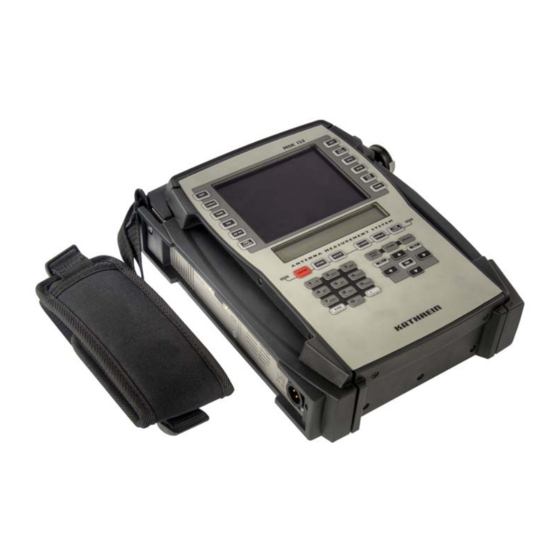
FUNCTIONALITY The MSK 125 is a mobile multi-purpose measuring device intended for analogue TV and satellite, FM radio and for DVB-C, DVB-S(2) and DVB-T for battery and mains operation. The integrated 6.5 Ah lithium-ion battery and a rechargeable 230 V AC power unit are included in the product package. - Page 9 FUNCTIONALITY...
-
Page 10: Operating And Display Elements
OPERATING AND DISPLAY ELEMENTS Measured values and settings are shown on the LCD display. LCD DISPLAY Depending on the operating mode and function, the LCD display shows • the selected channel, • the selected frequency, • the called function, • the operating mode, •... - Page 11 OPERATING AND DISPLAY ELEMENTS TFT Colour Display TV picture/settings Source selection Measurements LCD display Measurement results On/off button Settings Mode indicator LNB display Input pad Cursor pad...
-
Page 12: Overview Of Keypad Commands
OPERATING AND DISPLAY ELEMENTS OVERVIEW OF KEYPAD COMMANDS Button Brief description of the function Switching the device on/off Sources Selection of SAT operation and switch between analogue and digital SAT Selection of cable TV operation and switch between analogue cable TV and digital cable TV Selection of terrestrial TV operation and switch between analogue terrestrial TV and digital terrestrial TV FM radio selection... - Page 13 OPERATING AND DISPLAY ELEMENTS Cursor pad Reduce current values (frequency, channel, etc.) Increase current values (frequency, channel, etc.) Selection up Selection down Confi rm input or selection Reduce volume Increase volume Measurement memory management Store measurement device settings and measured values Retrieve measurement device settings and measured values Settings Default settings and setting the digital modulation parameters...
-
Page 14: Connections
DC supply EXTERNAL DC SUPPLY The MSK 125 can be operated with a mains supply or its own built-in battery. For mains operation, use the PSU and charger connected to the DC socket on the left-hand side of the MSK 125 enclosure. -
Page 15: Rf Input
MSK 125 for output to an external HDMI monitor. This output is only available with digital programmes. SCART SOCKET The video and audio signal is available at the SCART socket on the front of the MSK 125 for evaluation on an external monitor. The button also allows you to switch to audio/ video input. -
Page 16: Getting Started
• Adjust the desired volume using the button. The LCD display shows the current software version and the serial number of the MSK 125 for approx. 1 second. Now feed the reception signal from the receiver into the RF input socket. -
Page 17: Default Setup Settings At Time Of Shipment
LEVEL dBµV LOW LEVEL MUTE MAINS AND BATTERY OPERATION The MSK 125 can be operated with a mains supply or its own built-in battery. MAINS OPERATION Remove the AC power unit supplied (100 V ... 250 V) from its packaging and use it to connect the device to the mains supply. -
Page 18: Battery Operation
Battery operation is only possible if the battery is charged suffi ciently. Otherwise the MSK 125 cannot be switched on. Once the battery has fully discharged it must be recharged immediately to avoid damage to the battery. -
Page 19: Sat
ANALOGUE SATELLITE RECEPTION In “SAT” mode the MSK 125 can be set to the “Analogue” and “DVB-S(2)” types of reception. SAT ANALOGUE/DVB-S(2) SELECTION Press once = SAT analogue Press again = DVB-S(2) Press again = SAT analogue again FREQUENCY DISPLAY AND ENTRY To measure the level of an reception signal, you must fi... -
Page 20: Sat Transponder Frequency Input
SAT TRANSPONDER FREQUENCY INPUT Select “satellite reception” (analogue or digital) Enter frequency The frequency can be changed in 100 kHz increments Confi rm input The FRQ/CHAN button can be used to switch between SAT transponder frequency and SAT IF frequency display. Note To ensure that the SAT IF frequency can be correctly computed when the SAT transponder frequency is entered, the right LO... -
Page 21: Lnb Voltage And 22 Khz Selection
LNB VOLTAGE AND 22 KHZ SELECTION The LNB supply voltage is available at the RF socket. To turn on or change the LNB voltage, press the button. You will see a menu with four options: 1 = LNB-Voltage/22 kHz Sets the LNB voltage and changeover between High and Low band with the 22 kHz signal 2 = LO-Frequency Select the LNB local oscillator frequency... - Page 22 Command overview for LNB voltage Opens the LNB menu Selects LNB voltage Change LNB voltage in 0.1 V increments 22 kHz signal on/off Exit the LNB menu Example To select LNB voltage 14 V: Press LCD display: • LNB voltage: 14 V •...
-
Page 23: Sat Analogue" Level Measurement
SOUND CARRIER FREQUENCY SETTING Every analogue satellite video signal is assigned a number of sound carrier frequencies. On the MSK 125 you can listen to main and sub-carriers you choose. The sound carrier frequency can be adjusted from 5.0 MHz to 8.99 MHz in 10 kHz intervals. At 7.00 MHz the sound carrier bandwidth is automatically switched... - Page 24 • Sound carrier bandwidth: Narrow = 150 kHz • Operating mode: SAT analogue Note When “SAT analogue” mode is called the MSK 125 is always set to 7.02 MHZ sound carrier. Frequency changes to the audio carrier are only retained until you exit the “SAT analogue”...
-
Page 25: Digital Sat Reception
DIGITAL SAT RECEPTION In “SAT” mode the MSK 125 can be set to the “Analogue” and “DVB-S(2)” types of reception. FREQUENCY DISPLAY AND ENTRY To measure the level of an reception signal, you must fi rst input the desired frequency. The LCD display indicates the frequency and the measured level. -
Page 26: Lnb Voltage And 22 Khz Selection
Complete your frequency entry by pressing the button. The most recent frequency setting is retained even after you switch the MSK 125 off, provided it was entered with digits and confi rmed by pressing LNB VOLTAGE AND 22 KHZ SELECTION The LNB supply voltage is available at the RF socket. - Page 27 Command overview for LNB voltage Opens the LNB menu Selects LNB voltage Change LNB voltage in 0.1 V increments 22 kHz signal on/off Exit the LNB menu Example To select LNB voltage 14 V: Press LCD display: • LNB voltage: 14 V •...
-
Page 28: Sat Dvb-S(2)" Level Measurement
8 data bits and one additional parity bit for the recognition of transmission errors. Multiple code words form one DiSEqC command. Code words are entered in hex code. Code words Parity bit The MSK 125 can send signals based on DiSEqC 1.0 but not receive them. -
Page 29: Command Overview For Diseqc Tm
COMMAND OVERVIEW FOR DISEQC If a DiSEqC matrix is activated with a DiSEqC command, the analogue LNB control voltage must fi rst be set to the correct satellite frequency plane, i.e. if a vertical satellite frequency plane is required, the analogue LNB control voltage must be set to 14 V. - Page 30 Exit the DiSEqC menu Example of a “User” entry: You wish to check the Kathrein EXR 22 matrix. The command set for the EXR 22 matrix is E0 00 24 (LNB High) and E0 00 20 (LNB Low). Calling “DiSEqC ”:...
-
Page 31: Command Overview For "Framing Byte
COMMAND OVERVIEW FOR “FRAMING BYTE” Description Byte Command from master, one-time transmission Command from master, repeating transmission Command from master, awaiting response, fi rst transmission Command from master, awaiting response, repeated transmission Response from slave, “OK”, no errors detected Response from slave, command not supported by slave Response from slave, parity error detected Response from slave, command not recognised COMMAND OVERVIEW FOR “ADDRESS BYTE”... -
Page 32: Command Overview For "Command Byte
COMMAND OVERVIEW FOR “COMMAND BYTE” The MSK 125 can send commands based on DiSEqC 1.0, but cannot receive them. All commands that require DiSEqC (send and receive) are greyed in the table. Commands shown in bold are preferred for Kathrein switching matrices. -
Page 33: Command Overview For "Data Byte
Write N1 Set port group 1 Write N2 Expansion option Write N3 Expansion option Read A0 Read analogue value A0 Read A1 Read analogue value A1 Write A0 Set analogue value A0 Write A1 Set analogue value A1 Write A7 Set analogue value A7 LO string Read instantaneous frequency... -
Page 34: Scif - Single Cable Interface (Sat Single Cable System Diseqc Control)
SCIF – SINGLE CABLE INTERFACE (SAT SINGLE CABLE SYSTEM DISEQC CONTROL) Launch the LNB menu Select SCIF Press to select the type of single cable system LNB with one local oscillator (10200 MHz) TYPE 1 = for 4 receivers (UAS481) TYPE 2 = Single cable switching matrices for 2 local oscillators (9750 / 10600 MHz) for 8 receivers... - Page 35 SAT BAND selection for TYPE 1 Vertical polarisation Horizontal polarisation With the TYPE 1 SCIF system, there is no distinction between Low and High band because the LO of 10.2 GHz enables both reception bands simultaneously. Transponder Frequency Entry Now enter the transponder frequency. Confi...
- Page 36 Logging off a receiver: Press to log off this receiver. Type 2 = single-cable switching matrices for 2 local oscillators and 8 receivers If you have selected Type 2, you can now defi ne one of eight receiver frequencies. Press to select the 4 receiver.
- Page 37 Type 3 = single-cable switching matrices for 2 local oscillators and 4 receivers If you have selected Type 3, you can now defi ne one of four receiver frequencies. Press to select the 1 receiver. The transponder frequency which can be defi ned later is set to 1400 MHz. The measuring device automatically adjusts to the selected receiver frequency.
-
Page 38: Simple Diseqc Tm , Tone Burst
SIMPLE DISEQC , TONE BURST The Simple Tone Burst DiSEqC procedure is a simplifi ed form of the DiSEqC control. Two switching states are possible with this Simple DiSEqC , Tone Burst and Data Burst. COMMAND OVERVIEW FOR “SIMPLE DISEQC ”... -
Page 39: Mpeg Image Representation In Dvb-S(2)
MPEG IMAGE REPRESENTATION IN DVB-S(2) If you select DVB measurement by pressing , the TFT screen displays the list of programmes that can be received on the digital transport stream. Use the key to select the desired programme and confi rm your selection by pressing To select the programme, you can also enter the displayed programme number directly If the programme can be received free, the picture and sound of... -
Page 40: Locating Satellites
LOCATING SATELLITES function allows you to search for satellites whose transponder frequencies are unknown. The frequency range from 1000 to 2100 MHz is continuously scanned for reception signals. If a reception signal is detected, the reception level is indicated in the display in the form of an increasing or decreasing bar. The buttons allow you to set the measurement range to three sensitivity levels. -
Page 41: Finding Individual Reception Frequencies
FINDING INDIVIDUAL RECEPTION FREQUENCIES function allows you to adjust the antenna to the maximum reception signal. The display indicates the reception in the form of an increasing or decreasing bar. The buttons allow you to set the measurement range to three sensitivity levels. The bearing sound enables you to monitor the level. -
Page 42: Tv Measurement
TV MEASUREMENT ANALOGUE CABLE TV RECEPTION In “CABLE” mode the MSK 125 can be set to the “Analogue” and “DVB-C” types of reception. ANALOGUE CABLE/DVB-C SELECTION Press once = Analogue cable TV Press again = DVB-C Press again = analogue cable TV again... -
Page 43: Channel Display And Entry
TV MEASUREMENT CHANNEL DISPLAY AND ENTRY To measure the level of an reception signal, you must fi rst input the desired frequency. The following channels can be set: • Band I/III CH 01 to CH 12 in 7 MHz grid •... -
Page 44: Command Overview For Tv "Frequency Entry
The most recent frequency setting is retained even after you switch the MSK 125 off, provided it was entered with digits and confi rmed by pressing Please note that the full-stops before and after the channel number indicate to the precisely selected channel: CH: .10. -
Page 45: Level Overflow And Underflow
TV MEASUREMENT LEVEL OVERFLOW AND UNDERFLOW At a level < 30 dBμV the LCD display indicates an underfl ow. LCD display: • Channel: CH 05 • Operating mode: Analogue cable TV • Level: underfl ow At a level > 120 dBμV the LCD display indicates an overfl ow. LCD display: •... - Page 46 TV MEASUREMENT Example To measure audio carrier level spacing and level of TT1: Press now press and keep the button pressed. The LCD display shows the following values for approx. 1 second: • Audio carrier spacing frequency: 5.5 MHz • Audio/video carrier spacing: -13 dB •...
-
Page 47: Digital Cable Tv Reception
The audio carrier level is only displayed as long as the button is pressed. DIGITAL CABLE TV RECEPTION In “CABLE” mode the MSK 125 can be set to the “Analogue” and “DVB-C” types of reception. ANALOGUE CABLE/DVB-C SELECTION Press once... -
Page 48: Channel Display And Entry
TV MEASUREMENT CHANNEL DISPLAY AND ENTRY To measure the level of an reception signal, you must fi rst input the desired frequency. The following channels can be set: • Band I/III CH 01 to CH 12 in 7 MHz grid •... -
Page 49: Command Overview For "Tv Frequency Entry
The most recent frequency setting is retained even after you switch the MSK 125 off, provided it was entered with digits and confi rmed by pressing Please note that the full-stops before and after the channel number indicate to the precisely selected channel: CH: .10. -
Page 50: Level Measurement Of "Dvb-C" Signals
TV MEASUREMENT If you do not wish to change the modulation type, press • 1 = QAM 64 demodulation • 2 = QAM 128 demodulation • 3 = DOCSIS QAM 64 demodulation • 4 = QAM 256 demodulation After selecting the modulation type you are automatically directed to the symbol rate entry. -
Page 51: Mpeg Image Representation In Dvb-C
TV MEASUREMENT MPEG IMAGE REPRESENTATION IN DVB-C If you select DVB measurement by pressing , the TFT screen displays the list of programmes that can be received on the digital transport stream. Use the key to select the desired programme and confi... -
Page 52: Analogue Terrestrial Tv Reception
TV MEASUREMENT ANALOGUE TERRESTRIAL TV RECEPTION In “TERR” mode the MSK 125 can be set to the “Analogue” and “DVB-T/H” types of reception. ANALOGUE TERRESTRIAL / DVB-T/H SELECTION Press once = Analogue terrestrial TV Press again = DVB-T/H Press again = analogue terrestrial TV again HF STANDARD SELECTION –... -
Page 53: Channel Display And Entry
TV MEASUREMENT CHANNEL DISPLAY AND ENTRY To measure the level of a TV reception signal, you must fi rst enter the desired channel. The following channels can be set: • Band I/III CH 01 to CH 12 in 7 MHz grid •... -
Page 54: Command Overview For "Tv Frequency Entry
The most recent frequency setting is retained even after you switch the MSK 125 off, provided it was entered with digits and confi rmed by pressing Please note that the full-stops before and after the channel number indicate to the precisely selected channel: CH: .10. -
Page 55: Digital Terrestrial Tv Reception
TV MEASUREMENT DIGITAL TERRESTRIAL TV RECEPTION In “TERR” mode the MSK 125 can be set to the “Analogue” and “DVB-T/H” types of reception. ANALOGUE TERRESTRIAL / DVB T/H SELECTION Press once = Analogue terrestrial TV Press again = DVB-T/H Press again = analogue terrestrial TV again HF STANDARD SELECTION –... -
Page 56: Channel Display And Entry
TV MEASUREMENT CHANNEL DISPLAY AND ENTRY To measure the level of an reception signal, you must fi rst input the desired frequency. The following channels can be set: • Band I/III CH 01 to CH 12 in 7 MHz grid •... -
Page 57: Command Overview For "Tv Frequency Entry
The most recent frequency setting is retained even after you switch the MSK 125 off, provided it was “entered with digits” and confi rmed by pressing Please note that the full-stops before and after the channel number indicate to the precisely selected channel: CH: .10. -
Page 58: Dvb-T-/H Mer, Ber And Offset Measurement
TV MEASUREMENT DVB-T-/H MER, BER AND OFFSET MEASUREMENT The modulation error rate (MER), the bit error rate (BER) and the carrier frequency offset can be measured to evaluate the digital reception quality. To launch DVB-T/H measurement: In the “terrestrial digital” reception mode, press LCD display for DVB-T signals: •... -
Page 59: Nit Network Information Table For Dvb-T
TV MEASUREMENT NIT NETWORK INFORMATION TABLE FOR DVB-T If you select DVB measurement by pressing , the TFT screen displays the list of programmes that can be received on the digital transport stream. Press the decimal point button to receive the NIT. You will receive the operator's information fi... -
Page 60: Finding Individual Reception Frequencies
TV MEASUREMENT FINDING INDIVIDUAL RECEPTION FREQUENCIES function allows you to adjust the antenna to the maximum reception signal. The display indicates the reception in the form of an increasing or decreasing bar. The buttons allow you to set the measurement range to three sensitivity levels. The bearing sound enables you to monitor the level. -
Page 61: Nicam Audio Bit Error Rate Measurement
TV MEASUREMENT NICAM AUDIO BIT ERROR RATE MEASUREMENT The bit error rate (BER) can be measured to improvement Example evaluation of the audio quality of Nicam signals. Launch bit error rate measurement: Press Press If the quality of the Nicam signal is so good that no bit error can be detected, “BER=0.000”... -
Page 62: Fm Measurement
After launching the FM menu for the fi rst time you only have to enter the digit sequence for another frequency entry. The most recent frequency setting is retained even after you switch the MSK 125 off, provided it was entered with digits and confi rmed by pressing LEVEL MEASUREMENT When you have set a frequency the level is measured automatically and displayed in dBμV on the LCD display. -
Page 63: Level Overflow And Underflow
FM MEASUREMENT LEVEL OVERFLOW AND UNDERFLOW At a level < 30 dBμV the display indicates an underfl ow. LCD display: • Frequency: 104.8 MHz • Operating mode: FM • Level: underfl ow At a level > 120 dBμV the LCD display indicates an overfl ow. LCD display: •... -
Page 64: Spectrum Measurement
SPECTRUM MEASUREMENT To evaluate a receiver, the frequency spectrum in the ranges “Satellite”, “Cable”, “Terrestrial” and “FM” can be displayed on the screen. Spectrum measurement is launched from the respective modes (Sat, Cable, Terr or FM). Command for spectrum measurement: To exit the measuring task: Press again. -
Page 65: Tv Spectrum
SPECTRUM MEASUREMENT NARROW (1316.0 MHz) TV SPECTRUM The TV spectrum is divided up into four modes (see corresponding chapter), which can be selected using the buttons, see screenshot and description on the next page: 5 = Return Path... - Page 66 SPECTRUM MEASUREMENT FULL SPAN = entire TV range (44 ... 867 MHz) VHF (44 ... 467 MHz) UHF (467 ... 867 MHz)
-
Page 67: Return Path Spectrum
SPECTRUM MEASUREMENT The displayed center frequency is the previously set reception channel. NARROW (Center 210.25 MHz) ANALOGUE NARROW (Center 394.00 MHz) DIGITAL RETURN PATH SPECTRUM The displayed marker frequency shows the previously set reception frequency. RETURN PATH (4...65 MHz) ANALOGUE/DIGITAL FM SPECTRUM The displayed marker frequency shows the previously set reception frequency. -
Page 68: Storing Device Settings
STORING DEVICE SETTINGS STORING DEVICE SETTINGS TFT Display First select the measuring task! Indicates the stored settings on the TFT display and opens the entry fi eld to defi ne a storage place on the LCD display. Use the “Up” and “Down” buttons to scroll through the screen content. -
Page 69: Storing Measurement Results
STORING MEASUREMENT RESULTS STORING MEASUREMENT RESULTS IN THE DEVICE MEMORY TFT Display First select the measuring task and perform the measurement! The “Memory Explorer” command displays the stored measuring results on the TFT display. Use the “Up” and “Down” buttons to scroll through the screen content. -
Page 70: Deleting Measurement Results From The Device Memory
STORING MEASUREMENT RESULTS TFT Display DELETING MEASUREMENT RESULTS FROM THE DEVICE MEMORY TFT Display The “Memory Explorer” command displays the stored measuring results on the TFT display. Indicates the stored settings on the TFT display and opens the entry fi eld of the storage place where the measurement results are to be deleted. - Page 71 PC via USB connection or read, manage and print out the SD card directly on your PC! The required conversion program is available on our web site. Please go to “http://www.kathrein.de” then select “Service” “Software/Download” “Messgeräte” “MSK 125”.
-
Page 72: Data Logger
DATA LOGGER The “Data Logger” setting allows you to execute the stored measurement device settings in sequence and store the corresponding measurement results. The stored device settings are used for automatic measuring. Up to 100 (00 ... 99) different measurement series can be stored. Note Before using the “DATA LOGGER”... -
Page 73: Entering The Stop Line For Automatic Measuring
DATA LOGGER ENTERING THE STOP LINE FOR AUTOMATIC MEASURING Use the button and the two-digit setting storage number to select the stop line where automatic measuring is to stop. STARTING AND INTERRUPTING AUTOMATIC MEASURING Use the cursor button to start automatic measuring. -
Page 74: Storing The Data Logger Measurement Results On The Sd Card
DATA LOGGER STORING THE DATA LOGGER MEASUREMENT RESULTS ON THE SD CARD See: Storing measurement results on the SD card. Example Call up Data Logger Select start line Select stop line Start Automeasure When the run is complete: Launch measured value memory Get fi... -
Page 75: Maintenance
DEVICE CALIBRATION The calibration interval is dependent on use and operational demands, and should be between 1 and 2 years. Calibration can be carried out by Kathrein customer service. For address see next page. OUTSIDE CLEANING A soft cloth, lint-free duster or paint brush is recommended for cleaning the outside of the device. In case of heavier soiling it is also possible to use alcohol or a mild soap solution. -
Page 76: Customer Service
TECHNICAL CUSTOMER SUPPORT If, despite studying this operating manual, you still have questions about getting started with the unit or using it correctly, or if unexpected problems occur, please contact the Kathrein Technical Support: Tel: +49 8031 184-700... -
Page 77: Features
FEATURES • Level measurement of analogue and digital TV signals (TV, Sat, FM, DVB-S(2), DVB-C, DVB-T, DVB-H (2k, 8k mode)) • Image representation of analogue and digital TV signals • BER/MER measurement and indication • 5.7" TFT colour display, transfl ective (640 x 480 pixels) •... -
Page 78: Technical Data
TECHNICAL DATA Type MSK 125 Order no. 21710022 RF component Sat: 920 ... 2150, TV: 47 ... 862, Frequency range FM: 87 ... 108 Return path: 4...65 Frequency tuning (steps) Sat: 100 , TV/FM: 50 Standard: B, 7 TV standards (channel grid) - Page 79 TECHNICAL DATA DVB-T/H carrier offset measurement NiT display (Network Information Table) Level measuring component Measurement range dBµV 30 ... 120 Measurement accuracy ± 2 SAT: 6 MHz SAT-DVB: 6 MHz Measurement bandwidth TV: 250 kHz TV-DVB: 6 MHz FM: 250 kHz SAT: Mean value display Detector TV: Peak value display...
-
Page 80: Technical Appendix
• Bandwidth correction The following formula applies: C/N = reception signal level - ambient noise level - bandwidth correction (MSK 125 measurement bandwidth) 6 MHz Bandwidth correction value = 10 log –––––––––––––––––––––––––––––––––– RF bandwidth reception signal Bandwidth correction value = 6.37 dB for 26 MHz bandwidth (Astra) Bandwidth correction value = 7.78 dB for 36 MHz (Eutelsat, Intelsat, Kopernikus) -
Page 81: Diseqc Tm Commands For Kathrein Matrices
Vert. Horiz. DiSEqC command E0 00 38 F4 E0 00 38 F6 E0 00 38 F5 E0 00 38 F7 COMMAND SET FOR KATHREIN MATRIX EXR 20 EXR 20 Range POS. A POS. B DiSEqC command E0 00 22 E0 00 26... -
Page 82: Channel Tables
407.25 259.25 415.25 266.25 423.25 273.25 431.25 280.25 439.25 287.25 447.25 294.25 455.25 463.25 Channel grid: 7 MHz in VHF and USB/OSB - 8 MHz in UHF and SB The table shows channel, display of the MSK 125 and frequency... -
Page 83: Channel And Frequency Table, "Standard L" (Frequency In Mhz)
216.00 423.25 224.00 435.25 232.00 447.25 240.00 459.25 248.00 256.00 264.00 272.00 Channels marked with a * do not allow video and audio evaluation or audio carrier level measurement. The table shows channel, display of the MSK 125 and frequency. -
Page 84: Channel And Frequency Table, "Standard D/K" (Frequency In Mhz)
351.25 159.25 359.25 167.25 367.25 100.25 375.25 105.25 383.25 231.25 391.25 239.25 399.25 247.25 407.25 255.25 415.25 263.25 423.25 271.25 431.25 279.25 439.25 287.25 447.25 295.25 455.25 303.25 463.25 The table shows channel, display of the MSK 125 and frequency. -
Page 85: Channel And Frequency Table, "Standard I" (Frequency In Mhz)
351.25 159.25 359.25 167.25 367.25 100.25 375.25 105.25 383.25 231.25 391.25 239.25 399.25 247.25 407.25 255.25 415.25 263.25 423.25 271.25 431.25 279.25 439.25 287.25 447.25 295.25 455.25 303.25 463.25 The table shows channel, display of the MSK 125 and frequency. -
Page 86: Calculation Of Sat If Frequency Using The Msk 125
CALCULATION OF SAT IF FREQUENCY USING THE MSK 125 This is done as follows: IF = reception frequency - oscillation frequency The oscillation frequency is made up as follows: 9750 MHz oscillator frequency is used for a reception frequency between 10700 MHz and 11700 MHz. -
Page 87: Notes
NOTES... - Page 88 Internet: http://www.kathrein.de KATHREIN-Werke KG • Anton-Kathrein-Straße 1 - 3 P.O. Box 100 444 • 83004 Rosenheim GERMANY...
Need help?
Do you have a question about the MSK 125 and is the answer not in the manual?
Questions and answers