Table of Contents
Advertisement
Quick Links
Download this manual
See also:
Professional Shop Manual
Preliminary Shop Handbook
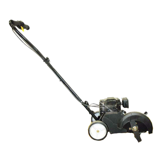
AC3 Edger
NOTE: These materials are for use by trained technicians who are experienced in the service and repair of outdoor power
equipment of the kind described in this publication, and are not intended for use by untrained or inexperienced individuals.
These materials are intended to provide supplemental information to assist the trained technician. Untrained or inexperi-
enced individuals should seek the assistance of an experienced and trained professional. Read, understand, and follow all
instructions and use common sense when working on power equipment. This includes the contents of the product's Oper-
ators Manual, supplied with the equipment. No liability can be accepted for any inaccuracies or omission in this publication,
although care has been taken to make it as complete and accurate as possible at the time of publication. However, due to
the variety of outdoor power equipment and continuing product changes that occur over time, updates will be made to these
instructions from time to time. Therefore, it may be necessary to obtain the latest materials before servicing or repairing a
product. The company reserves the right to make changes at any time to this publication without prior notice and without
incurring an obligation to make such changes to previously published versions. Instructions, photographs and illustrations
used in this publication are for reference use only and may not depict actual model and component parts.
© Copyright 2006 MTD Products Inc. All Rights Reserved
MTD Products Inc - Product Training and Education Department
FORM NUMBER - 769-02775
10/2006
Advertisement
Table of Contents
Troubleshooting

Related Manuals for MTD AC3


Summary of Contents for MTD AC3
- Page 1 Instructions, photographs and illustrations used in this publication are for reference use only and may not depict actual model and component parts. © Copyright 2006 MTD Products Inc. All Rights Reserved MTD Products Inc - Product Training and Education Department...
-
Page 3: Table Of Contents
Table of Contents INTRODUCTION ........................1 PERIODIC MAINTENANCE......................2 INITIAL TROUBLESHOOTING....................5 TROUBLESHOOTING THE IGNITION SYSTEM ............... 7 TROUBLESHOOTING THE FUEL SYSTEM ................9 TROUBLESHOOTING/ REPAIRING THE CARBURETOR............10 BLADE AND BELT ........................14 STARTER ..........................16 FUEL SYSTEM.......................... 17 IGNITION SYSTEM ........................ -
Page 5: Introduction
For the 2007 season, MTD introduced a compact • Most of the fasteners used on the blower are edger. This edger uses the new AC3 four cycle engine sized in fractional inches. Some are metric. that was introduced in the spring of 2006. -
Page 6: Periodic Maintenance
The oil on this engine should be changed after the first 10 hours of use and every 25 hours there after. To change the oil in the AC3 engine you must unscrew the oil fill plug in the crank case cover. - Page 7 Inspect the spark arrestor. See Figure 2.4. Spark Plug To remove the spark plug: Unplug the spark plug wire. CAUTION: Do not grab the spark plug wire with pliers. Damage to the sparkplug boot will result. A damaged spark plug boot will weaken the spark of the spark plug.
- Page 8 Check the valve lash by placing a feeler gauge Install the engine cover. between the rocker and the valve stem. To NOTE: There are six screws for the engine adjust the valve loosen or tighten the fulcrum nut cover, three that go into the engine block casting with a 8mm wrench until there is a slight drag on and three that go into the starter housing.
-
Page 9: Initial Troubleshooting
To reach the air filter remove the cover. INITIAL TROUBLE SHOOTING 1a. Remove the air filter cover by pressing in The first step in diagnosing an engine problem is to the tab on the side of the filter housing perform the periodic maintenance. A majority of the and lifting the cover off. - Page 10 Inspect the spark plug: 6d. If the engine starts and runs long enough to burn the prime, the problem is effectively • What does the spark plug look like? isolated to the fuel system. proceed to the • A dry fowled plug could mean the engine is run- Troubleshooting the Fuel System section ning rich.
-
Page 11: Troubleshooting The Ignition System
Check and adjust the valve lash by following the TROUBLESHOOTING THE IGNITION SYSTEM procedures described in the section on periodic To test the ignition system: maintenance. Disconnect the spark plug wire. Test run the engine before returning it to service. Connect a spark tester to the spark plug wire. - Page 12 Disconnect the red wire. See Figure 4.2. With the switch in the engine run position (l), the meter should indicate no continuity. See Figure 4.3. Disconnect the red wire Switch in the engine run position Figure 4.2 Figure 4.3 Install the starter as described in the “starter” section of this manual.
-
Page 13: Troubleshooting The Fuel System
TROUBLESHOOTING THE FUEL SYSTEM NOTE: If the results are not as described, the Drain and inspect the fuel: switch is bad and should be replaced. • Look for water. If there is reason to suspect that the ignition tim- • Look for dirt. -
Page 14: Troubleshooting/ Repairing The Carburetor
TROUBLESHOOTING/REPAIRING THE CAR- BURETOR NOTE: A cracked spacer or a leaking gasket Typically, troubleshooting the carburetor is the last step between the spacer and the cylinder could result in the diagnostic process. The other factors are more in a lean run or prevent the impulses from the readily identified;... - Page 15 Inspect the throttle valve assemble for debris Disconnect the throttle cable by unhooking the and freedom of movement. See Figure 6.4.. Z-fitting. See Figure 6.5. Throttle valve assembly Unhook the Z-fitting Figure 6.4 Figure 6.5 If there is a problem with the throttle valve Place the carburetor in a clean area on the work assembly, check on availability and price of parts bench.
- Page 16 Inspect the metering valve and the metering Inspect the diaphragms for brittleness and/or valve seat for dirt and/or pitting. See Figure 6.7. damage. NOTE: The carburetor used in this manual is a Walbro. Depending on the application the engine may have a different carburetor. All car- buretors have a manufacturer name cast on them.
- Page 17 The orifice can also be seen from the pump side Set the needle valve lever as per the carburetor of the throttle housing. See Figure 6.11. manufacturer’s recommendations using a W- tool. See Figure 6.13. Orifice Pump spring Needle valve lever Figure 6.11 Figure 6.13 The fuel pump in the carburetor is driven by vac-...
-
Page 18: Blade And Belt
BLADE AND BELT Remove the three screws holding the blade guard in place using a T-40 Torx driver. Blade removal/replacement See Figure 7.2. Remove the blade retaining nut with a 15/16” socket and an impact wrench. See Figure 7.1. Remove these three screws Blade retaining nut Figure 7.2 Figure 7.1... - Page 19 Remove the belt cover by removing the three Remove the spindle pulley. See Figure 7.6. screws using a T-20 Torx driver. See Figure 7.4. Spindle pulley Remove these three screws Figure 7.6 Figure 7.4 The belt will now slide off. Remove the belt guide using a 3/8”...
-
Page 20: Starter
STARTER REMOVAL Remove the screws that hold the engine cover to the starter housing. See Figure 8.3. Remove the belt cover and belt following the steps described in the Belt and Blade section. Remove the spark plug. Insert a long length of rope into the cylinder to Remove these block the engine. -
Page 21: Fuel System
To get at the internal components of the starter FUEL SYSTEM REPAIR remove the three screws in the pressure plate The fuel system consists of: and cut off the starter pulley retaining ring. See Figure 8.5. • The fuel tank (including the cap and fuel lines) •... - Page 22 Carefully remove the fuel line from the nipple on Remove the engine cover by removing the six the fuel filter. Discard the old fuel filter. screws that hold it in place. See Figure 9.5. See Figure 9.3. Fuel line Six screws Nipple Engine cover removed Figure 9.5...
-
Page 23: Ignition System
Insert the two tabs into the two slots in the starter IGNITION SYSTEM REPAIR housing. The ignition system consists of: • Connect the fuel lines to the carburetor. The blue • The flywheel line is the return line and the clear line is the sup- ply line. - Page 24 Place a brass .010” feeler gauge on the flywheel Inspect the flywheel key for any signs of dam- magnets and rotate the flywheel until the mag- age. nets line up with the module. Let the magnets Install the flywheel by following the previous pro- draw the module against the flywheel with the cedure in reverse order.
Need help?
Do you have a question about the AC3 and is the answer not in the manual?
Questions and answers