Table of Contents
Advertisement
Quick Links
B573 User
Manual
B573 Ethernet Router and B573 Media Connector Software
TCT Router and FLN5 RS-485 Floor Bridge Applications
Overview
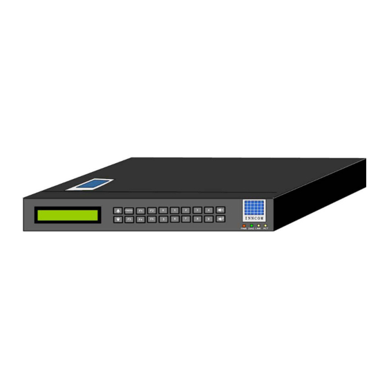
INNCOM's B573 Ethernet Router
The B573 is configured by the software loaded into it at the factory to support 4 types of applications:
TCT Router (MBX) Application : Inncom related data (room temperature, occupancy, rental status, etc) to/from
the guestroom is sent through a TCT room gateway device located in each guestroom. The TCT is connected to
a network hub or switch inside the guestroom that is connected to the hotels "guest-side" (or public) network. A
single B573 connected to the "guest-side" (or public) network is programmed to rout Inncom data to and from all
of the TCT's , and then make this data available to the Inncom software running on the Inncom server.
RS-485 FLN5 (Floor Level Network 5) Floor Bridge Application: Inncom related data (room temperature,
occupancy, rental status, etc) to/from the guestroom is sent via an RS-485 twisted pair wiring network connected
between the room gateway device (ie E528 thermostat, X529 , TCC, B485, etc) and the RS-485 Com ports on
the rear of the B573. This data is then made available to the Inncom software running on the Inncom server.
Room Gateway Application: Whereas the above mentioned TCT Router (MBX) and RS-485 FLN5 Floor Bridge
modes of the B573 are intended to rout data from all connected room gateway devices toward the Inncom Server
computer,
the B573 itself can be programmed to act as an advanced room gateway device in installations
where guestrooms contain a tablet PC device. The specialized wireless communication protocols used by the
tablet PC device require a special B573 room gateway device to be installed. The B573 programmed as a Room
Gateway acts as an advanced TCT and bridges these specialized tablet PC protocols to a B573 TCT Router
(MBX), which in turn makes the information available to the Inncom Server.
FLN5 (Floor Level Network 5) Reflector Application: A B573 programmed as an "FLN5 Reflector" is used at
installations containing large, multi room suites that can not be adequately managed by the normal Inncom suite
linking functionality.
The TCT Router (MBX) and RS-485 FLN5 Floor Bridge applications are the most common. In both of these
applications, the B573 routs Inncom related messages from all connected room gateway devices to/from the
Inncom Server. The only difference being the type of physical network used to connect the room gateway device
to the B573. For the TCT MBX application, the hotels TCP/IP Ethernet network is utilized. For the RS-485
FLN5 application, a serial RS-485 twisted pair network is utilized.
The TCT Router (MBX) and RS-485 FLN5
Floor Bridge applications will be covered in detail by this document.
The Room Gateway and FLN5 Reflector applications are much less commonly used and are not covered by this
document. Refer to Inncom application note "AN214 Suite Linking with Reflection" for details on the FLN5
Reflector mode, and Section 3.4 of the B573 Engineering manual for details on the B573 Room Gateway mode.
277 · West Main Street· Niantic, CT · USA · 860-739-4468 · www.inncom.com
1
Advertisement
Table of Contents

Summary of Contents for Inncom B573
- Page 1 (ie E528 thermostat, X529 , TCC, B485, etc) and the RS-485 Com ports on the rear of the B573. This data is then made available to the Inncom software running on the Inncom server. Room Gateway Application: Whereas the above mentioned TCT Router (MBX) and RS-485 FLN5 Floor Bridge...
- Page 2 Revision 1.2, Issued 5/15/08 B573 MBX (TCT Router) Application A single B573 configured as an "MBX" is used at a hotel that has a pre-existing TCP/IP Ethernet network installed. An Inncom TCT "room Ethernet gateway" device is installed in each guestroom. The TCT sends/receives Inncom related room information to and from the B573 MBX router over the “guestroom”...
- Page 3 E528, X529 , B485 or K592). The Inncom data from the "room gateway" device entering the B573 via the RS485 Com A or COM B ports is routed to the Ethernet network by the B573, where it is picked up by the "B573 Media Connector"...
-
Page 4: Table Of Contents
1.4 Set the Network IP Address and Subnet Mask of the B573 ............13 “Ping” B573 IP Address From Inncom Server Computer ..............14 1.5 Verify / Set the TCT Port Offset If Configuring a B573 MBX TCT Router......... 15 1.6 Configure and Save B573 Media Connector Software Script File (B573_MC.cfg) ..... 16 1.7 Configure and Save the WinP5PT.p5s script file to Support B573(s)........... -
Page 5: Section 1: B573 Installation
Section 1: B573 Installation Read First: The B573 is not a stand-alone device like its predecessor, the B572. For its intended operation as a bridge/router, the B573 hardware relies on being “connected” to a software program called the “B573_MC.exe” (B573 Media Connector) that must always be running on the Inncom server computer: The B573 is “dumb”... - Page 6 The B573 requires a fixed (static) network IP Address. This is programmed into the B573 using the front panel LCD display and buttons. The B573 DOES NOT support DHCP. You must coordinate with the hotels IT department to obtain a fixed IP address for each installed B573 and program it into the B573. •...
-
Page 7: Mount The B573
Attach the mounting brackets to the B573 body using the provided machine screws as shown in Figure 1. Three tapped holes are on the left and right sides of the B573 near the front of the B573 to accept the machine screws. -
Page 8: Connect Communication Wiring To The B573
Ethernet patch cable that connects the B573 to the same network that has all the TCT’s attached. Connect the network patch cable from the switch or hub that places the B573 on the TCT network to the RJ45 network jack (labeled I/O Base) on the rear of the B573 277 ·... - Page 9 2-pin green terminal blocks provided with the B573. Read the notes on page 10. 2. Connect the network patch cable from the switch or hub that places the B573 on the same network as the Inncom server to the RJ45 network jack (labeled I/O Base) on the rear of the B573.
- Page 10 Before making any actual termination between the RS-485 pair coming from a particular room and the B573 COM port , verify the pair has no shorts or excessive voltage present that may indicate the wiring pair has a problem that could damage the B573 when connected.
-
Page 11: Power The B573
Power Option 1: B573 receives power from 12VDC power connected to the 12VDC Power jack (red circle shown below). A 2.1mm, center pin positive DC power jack is provided at the lower right on the back of the B573 to connect a 12VDC power supply. -
Page 12: Important: Notes On Grounding The B573
If the B573 has the optional 120/240VAC power supply installed, the AC power source that you connect the AC line cord from the B573 to must have a valid earth ground connection. The ground pin on the “AC In” socket on the rear of the B573 is physically connected to the B573 metal housing and to any “common”... -
Page 13: Set The Network Ip Address And Subnet Mask Of The B573
B573 front panel buttons and display. . You may need to consult with the properties IT department to obtain the IP address and Subnet to be set into the B573. If installing multiple B573's, you will need a unique IP address for each B573. -
Page 14: Ping" B573 Ip Address From Inncom Server Computer
Enter key. c. If the B573 with the defined IP address replies, you will see 4 replies appear in the DOS window , here an audible “click” from the B573 and see the IP Address of the “pinging” computer on the B573 display (see note below) for each of the 4 replies. -
Page 15: Verify / Set The Tct Port Offset If Configuring A B573 Mbx Tct Router
The B573 MBX supports changing this TCT Port value by adding an offset value to the baseline value of 23210. This is done to allow more than one B573 MBX to be used on the same network. However using more than one B573 MBX is only done under special rare circumstances. -
Page 16: Configure And Save B573 Media Connector Software Script File (B573_Mc.cfg)
; If using FLN5 room gateways, the FLN5 tag must be set in each line. ; If the number of rooms is not known, leave at 0. If set, B573 will display "x rooms of y", quickly showing ; how many non-communicating rooms are on that bridge. - Page 17 If that is the case, used “Watchdog” to restart the “B573_MC.exe” program. • If the IP address of any B573 changes, the "B573_MC.cfg" script file must be updated with the new IP address and saved. The "B573_MC.exe" program must then be re-started for the change to take effect.
-
Page 18: Configure And Save The Winp5Pt.p5S Script File To Support B573(S)
WinP5PT.p5s script file. a. If the property was using an older B572 MBX to support TCT’s and you are replacing it with a new B573 MBX, there will be a pre-existiing line in the Media section of the WinP5PT.p5s script file that defined the IP address of the existing B572 MBX similar to: $Media: B572 IP: XXX.XXX.XXX Port: 7002 (XXX.XXX.XXX is IP address of existing B572) -
Page 19: Start "Winp5Pt.exe" And "B573_Mc.exe" Programs And Verify Operation
The current Windows system time of the Inncom server. If after 1-2 minutes the “Status” for a defined B573 remains “Not Connected” and the LCD display on the particular B573 has not changed to the “connected” screen, verify the following: •... - Page 20 B573 User Manual Revision 1.2, Issued 5/15/08 • Verify the particular B573 is configured as an FLN5 RS-485 bridge. Verify the line item for the particular B573 in the “B573_MC.cfg” script file has “FLN5: Y” at the end of the line. •...
-
Page 21: Verifying Room Communication
B573(s). 1. You can verify room gateway communication locally at the B573 **. This feature is useful if you do not have access to the Inncom Server or a remote Inncontrol terminal. From the B573 front panel using the LCD display and keypad, enter the “1.2 Function”... -
Page 22: Section 2: Accessing And Using The B573 Lcd Display Menu Screens
Section 2: Accessing and Using the B573 LCD Display Menu Screens Section 1 covered installing the B573 , accessing the necessary B573 local menu functions from the B573 front panel to set the B573 IP address and subnet and configuring the “B573_MC.exe” (B573 Media Connector) software script file (“B573_MC.cfg”) to connect to installed B573’s. -
Page 23: Server Menu
“Server” sub-menus to appear. If the “B573_MC.exe” software is NOT running, or the particular B573 is NOT connected to the “B573_MC.exe” software because the IP address of the B573 does not match the IP address in the “B573_MC.cfg” script file, pressing the Enter button with “1. -
Page 24: Trace Menu
Accessing the 1.1.2 Trace Message menu provides the ability to trace specific message types. 1.1.2.1 Trace PI – The B573 displays “Tracing: PI” on the first line, and room IDs of any rooms reporting a process image on the second line. - Page 25 1.1.3.2 Trace FLN5-A: This option will only be available if the B573 is configured as an FLN5 RS-485 Floor bridge. Shows messages for all rooms connected to the COM_A port on the back of the B573. “Tracing: FLN5-A” will be displayed on the first line and the room# and message on the second line.
-
Page 26: Function Menu
. • If an FLN5 RS-485 B573, “Com A = x, Com B = “ where “x” and “y” are the number of rooms actually communicating on the COM_A and COM_B RS-485 com port of the particular B573. -
Page 27: Setup Menu
The only function that would possibly be used is to access the 2.12 NVRAM menu to change the “TCT Port Offset” value if the B573 is configured as an “MBX” to support TCTs. This is covered in Section 1.5 on page 15 of this document. -
Page 28: Network Menu
Revision 1.2, Issued 5/15/08 2.1 Network Menu From the 2.1 Network menu, you can set the Network IP Address and Subnet of the B573 2.1.1 IP Address - Set IP Address of the B573 using the following steps : 2.1.2 Subnet Mask – Set Network Subnet Address in the B573 using the following steps: 2.1.3 VLAN Tag - Not Required or utilized at this time... -
Page 29: Device Menu
2.2.1 Backlight : Turn the B573 LCD display backlight On or Off 2.2.2 Show Ping : Turn On or OFF the setting to visually and audibly indicate the B573 IP Address is being “pinged” from a computer. When On, if you “ping” the B573 IP address from a computer, the B573 will emit an audible “click”... -
Page 30: Fln5 Test Pattern Menu
DC voltage on the “A” and “B” terminals for each FLN5 Com Port (COM_A and COM_B) Press any button on the B573 front panel to STOP the FLN5 test pattern and Reset the B573. With this test signal present, a fixed, known DC voltage will be present at the COM_A and COM_B RS-485 outputs of the B573 that can be measured with a meter set to measure DC voltage. -
Page 31: Utility Menu
If the B573 has connected to the B573_MC.exe software, the IP Address and network MAC address of the Inncom Server computer (ie computer running the B573_MC.exe program) will be displayed. If the B573 is NOT connected to the B573_MC.exe program, no MAC address or IP address will be displayed. -
Page 32: B573 Troubleshooting
B573 has no power applied. 1. Review the section on powering the B573 on page 11. B573 Front LCD does not show the The B573 is not connected to the Is the network patch cable that number of connected rooms to that network. - Page 33 Verify the B573 MBX is Server. connected to the hotel “guest” network (ie the network that all The IP address for the B573 MBX the room TCT devices are is not defined (or is defined connected to). incorrectly) in the “B573_MC.cfg”...
- Page 34 INNControl software running on the hardware or wiring that connects Inncom server. Inncom server or terminal. the B573(s) to the Inncom Server. Verify the B573(s) is/are The “B573_MC.cfg” script file is not connected to the same network present in the “C:\Inncom\Scripts”...
- Page 35 RS-485 wiring pair from the installed, and a GROUP of rooms to a B573, or there is an issue with rooms connects to the B573 is appear as NOT communicating on the wiring (ie rooms not punched...
- Page 36 “$B573: IP:…….” line in the “B573_MC.cfg” script (see Figure A.4 below). The “FLN5: Y” is not used only when using a single B573 set to “MBX” mode to be used with TCT’s. It must be there for FLN5 Floor bridge mode B573s.
- Page 37 "Ping" the B573 from the Inncom server computer. You must first know the network IP address of the particular B573 . This may be written on a sticker applied to the particular B573, but the easiest way is to actually read the IP address from the B573 "Utility"...
-
Page 38: Technical Specifications
B573 powered from 12VDC Only: Inncom P/N 01-9981. 120VAC to Dual 12VDC power supply Inncom P/N 04-4040 B573 with optional 100/240 VAC power supply: Inncom P/N 01-9981.A1 B573 120VAC power supply: Inncom P/N 02-9978 6 ft AC Line Cord (for 01-9981.A1 / 02-9978):... -
Page 39: B573 Front Panel Button And Led Descriptions
Front Panel LED Descriptions RED “PWR” LED : On when power is applied to B573. GREEN “DIAG” LED : Blinks twice rapidly each second when B573 IS connected to “B573_MC.exe” program Blinks once each second when B573 IS NOT connected to “B573_MC.exe” program. -
Page 40: References
Revision 1.2, Issued 5/15/08 References B573 Engineering Manual INNCOM B573 Media Connector User's Guide IWAN User's Manual Note: These manuals will be provided by INNCOM upon request. Document Revision History Table 2. Document Revision History REVISION DATE ISSUED REASON FOR CHANGE First issue 1.0...
Need help?
Do you have a question about the B573 and is the answer not in the manual?
Questions and answers