Table of Contents
Advertisement
Quick Links
Advertisement
Table of Contents

Related Manuals for Motorola V3682


Summary of Contents for Motorola V3682
- Page 1 V3682 Level III Service Manual Single Band 1900 MHz GSM...
-
Page 2: Table Of Contents
V3682 CONTENTS Page Number SECTION 1: GENERAL Introduction Motorola service policy for V3682 in warranty General Safety Information SECTION 2: V3682 DESCRIPTION Specifications of V3682 V3682 Overview Connector Pinout Talk time, Weight and Volume Matrix SECTION 3: FEATURE LIST List of Features available... - Page 3 V3682 Flexing Testing on HP 8922 Testing PCB only on Car Kit Set Up Testing on Go / NoGo Tester SECTION 7: ACCESSORIES Accessory Statement SECTION 8: GLOSSARY OF TERMS List of Abbreviations of 46 European Customer Services...
-
Page 4: Section 1: General
V3682 SECTION 1: GENERAL of 46 European Customer Services... -
Page 5: Introduction
The scope of this document is to provide the reader with basic information relating to the V3682, and also to provide procedures and processes for repairing the units up to and including Level 2 repair. -
Page 6: Motorola Service Policy For V3682 In Warranty
Only shops authorized to carry out repairs will be able to purchase spare parts. Orders for spare parts should be placed with the Accessories and Aftermarket Division (AAD) of Motorola. Refer to the latest version of CSB 260 for details. -
Page 7: General Safety Information
In standby mode the mobile telephone will automatically transmit to acknowledge a call if it is not turned off. • Refer to the appropriate section of the product user manual for additional pertinent safety information • All equipment should be serviced only by a Motorola qualified technician. of 46 European Customer Services... -
Page 8: Section 2: V3682 Description
V3682 SECTION 2: V3682 DESCRIPTION of 46 European Customer Services... -
Page 9: Specifications Of V3682
V3682 Specifications of V3682 General Function Specification Frequency Range GSM PCS 1850.2 - 1909.8 MHz Tx 1930.2 - 1989.8 MHz Rx Channel Spacing 200 kHz Channels 174 GSM/374 DCS carriers with 8 channels per carrier Modulation GMSK at BT = 0.3... -
Page 10: V3682 Overview
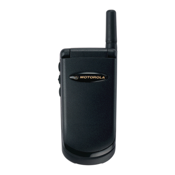
V3682 V3682 Overview The V3682 has been marketed as the lightest and smallest dual band mobile phone in the world. It is now designed with the new Whitecap Chipset to allow the unit to operate at a lower working voltage and therefore prolong battery life, in both Standby and Talk time. -
Page 11: Connector Pinout
V3682 2.3 Connector Pinout 1- RF Ground 2- RF In/Out 3- RF Ground 4- Battery Feedback 5- Manual Test Line 6- Not connected 7- Not Connected 8- Audio In 9- Audio Out / On-Off 10- Battery Ground 11- RTN 12- CMP... -
Page 12: Section 3: Feature List
V3682 SECTION 3: FEATURE LIST of 46 European Customer Services... -
Page 13: List Of Features Available
V3682 List of Features Available Below are the list of Menu functions available at present, all highlighted text are or menu options that may be added in future versions i.e. on the release of Voice Annotation. Below are the list of Menu functions available at present, all highlighted text are or menu options that may be added in future versions i.e. -
Page 14: Call Related Features
V3682 CALL RELATED FEATURES Show battery meter 1.Show ID on next call Restrict my 2.Restrict ID on next call Phone number Call Diverting 1.On Talk and Fax 2.Off Call waiting 1.On 2.Off Call Barring 1.Int’l Calls Bar outgoing calls 2.Int’l Calls Except home 3.All Calls... -
Page 15: Messages
V3682 Messages Call Voicemail Received messages Go to Next message Delete Message Return Call 1.Send Message Edit Message 2.Store Message Reply to message Delete all messages Outgoing Messages Go to next message Send message 1.Send message Edit message 2.Store message Delete message 1.On... -
Page 16: Phone Setup
V3682 PHONE SETUP Select Phone line Adjust Ring volume 1.Ring only 2.Vibrate only Ring or Vibrate 3.Vibrate then ring Standard Tone 4.No ring or vibrate Set Ringer Tone Music Tone Set Ringer Tone 2 1.On Automatic Lock Phone Lock 2.Off... -
Page 17: Network Selection
V3682 NETWORK SELECTION Available 1.Register Now Networks 2.Make Preferred Registration 1.Automatic Search Network Search Preferences 2.Manual Search 1.Slow Search 2.Medium Search Frequency of 3.Fast Search Search 4.Continuous Search Preferred 1.Choose From Available Add network Networks 2.Choose From Known to List 3.Add new Network Code... -
Page 18: Accessory Setup
V3682 ACCESSORY SETUP NB. THIS MENU IS ONLY AVAILABLE WITH EITHER HEADSET PLUGGED IN OR WHEN INSTALLED IN A CAR KIT. 1.On Mute Car Radio 2.Off Dependant on 1.On Automatic answer type of car kit 2.Off 1.On Automatic Handsfree 2.Off 1.On... -
Page 19: Section 4: Disassembly & Parts
V3682 SECTION 4: DISASSEMBLY & PARTS of 46 European Customer Services... -
Page 20: Dissasembly Introduction
4.1 Disassembly Introduction The V3682 has no screws to hold it together and is held together by plastic catches, these are delicate and should be parted using the upmost care. Also the display flex cable can be torn or broken without too much stress being applied so again caution should be taken on dissassembly or assembly. - Page 21 V3682 2.Remove the battery 3.Push down on Antenna 1.Remove Battery door from pushing from the and screw Antenna Anti- by pressing up on latch bottom and lifting clockwise. and pulling door. outwards. 5.Push tool between latch 4.Remove the LED and housing to prize open...
- Page 22 V3682 7.Carefully lift the retaining 6.Remove with care the clip on the flex connector. backhousing from the front. Then pull the flex from the connector. Remove keypad 8.Lift PCB out of PCB from board front housing of 46 European Customer Services...
-
Page 23: Exploded Parts Diagram
V3682 Exploded Parts Diagram SWF3076DA of 46 European Customer Services... -
Page 24: Replacement Parts
V3682 Replacement Parts Xcvr Item Number SWF3076DA Spare Xcvr Number SE0044AB1Z1 Rear Hsng 0104793Z01 Hinge Mechanism 5504765Z02 Frnt Hsng Assy 0104792Z01 Flip Assy 0185763G01 Keypad PCB SYN6939A Keypad 3809378T02 SW Array Domes 4004877Z02 Escutcheon 5403796S01 Lens 6185833G02 Mic grommet 0585699J01... -
Page 25: Section 5: Sim Cards And Security
V3682 SECTION 5: SIM CARDS AND SECURITY of 46 European Customer Services... -
Page 26: Manual Test Mode
V3682 5.1 Manual Test Mode The GSM Motorola V3682 is equipped with a manual test mode capability. This capability allows service personnel to take control of the unit, and by entering certain keypad commands, make the unit performs desired functions. - Page 27 V3682 4. Insert card into replacement unit, or unit with new main RF / Logic PCB. 5. Turn unit on wait till ‘Clone’ appears. 6. Enter 03# ‘Please wait’ will be displayed while data is transferred. 7. Repeat steps 1 – 6 but enter 022# at step 2 to transfer data on to Clone card.
-
Page 28: Gsm Test Command
V3682 GSM Test Commands This is a list of Level 1 and 2 Test commands available to V3682 Table 6.1 Test commands GSM Test Commands Key Sequence Test Function/Name #(hold down for 2 seconds) Enter manual test mode Exit manual test mode... -
Page 29: Identity And Security
The mechanical Serial Number (MSN) is an individual unit identity number and will remain with the unit throughout the life of the unit. The MSN can be used to log and track a unit on Motorola’s EPPRS system. The MSN is divided into 4 sections. -
Page 30: Section 6: Repair & Test Procedures
V3682 SECTION 6: REPAIR AND TEST PROCEDURES of 46 European Customer Services... -
Page 31: Repair Introduction
V3682 6.1 Repair Introduction The V3682 is divided into 4 main sections when it comes to part replacability: The flip which contains the display module and speaker, the mechanical parts, the keypad PCB and the main RF / Logic PCB. - Page 32 V3682 Repair Chart Table 2. GSM V3682 Cellular Telephone: Troubleshooting and Repair Chart. (Assembly Replacement Level). SYMPTOM PROBABLE CAUSE VERIFICATION AND REMEDY Personal telephone will not turn a) Battery pack either discharged Measure battery voltage across a 50 ohm (>1 Watt)
- Page 33 V3682 SYMPTOM PROBABLE CAUSE VERIFICATION AND REMEDY a) Faulty alert Transducer / Main Replace Logic/RF Board Assembly (refer to 4. Incoming call alert transducer RF / Logic PCB defective symptom 1c). Verify that the fault has been cleared audio distorted or volume is too and re-assemble the unit with the new PCB.
-
Page 34: Software Upgrade
V3682 SYMPTOM PROBABLE CAUSE VERIFICATION AND REMEDY b) Reed Switch defective Gain access to Keypad board as described in the DISASSEMBLY instructions in this manual. Unsolder the reed switch and replace with a known good one. Reassemble unit. Place call to portable phone and verify ability to answer by opening flip. -
Page 35: Testing On Hp 8922
GSM Test 83220E Down Converter Power Supply Signal Cable RF Cable V3682 under Test Audio test cable, Battery and adapter. (See Emulator prototype picture) NB At the time of release a final version for the Audio cable was unavailable; a photo and part number will be available as soon as the final release is available. - Page 36 Testing on Car Kit Set Up SSN4020A - Speaker SYN7066C – DSP Box SMN4103A - Extension Cable – SKN4419A Startac handset Junction Box – SCN2636A – SLN6749A SKN4491A – V3682 under RF Cable Test 2700 external card reader – SLN6749A of 46 European Customer Services...
-
Page 37: Testing On Go / Nogo Tester
V3682 Testing on Go / NoGo tester The set up for the GO / NOGO tester must be set up as per above. The tester must be set up as per GSM specifications. The test incorporates the basic live call, during which many of the RF parameters are checked. This test can be ran in ‘Autotest’... -
Page 38: Section 7: Accessories
V3682 SECTION 7: ACCESSORIES of 46 European Customer Services... - Page 39 V3682 7.1 Introduction A lthough the B attery packages are completely different to those used in the other Startac ranges, the accessory socket remains standard so a great deal of the Startac type accessories are still compatible. There is no requirement for any A uxiliary battery.
- Page 40 SJN8635A – Manual Insert The V3682 Voice Recognition Car kit is a professional install handsfree car kit with improved full duplex performances for the StarTAC models. The Kit uses the latest Digital Signal Processor (DSP) technology for high quality audio as well as Voice Recognition (VR) algorythms, and includes all basic handsfree components, hang up cup, DSP HF box, speaker, directional microphone, and cables.
- Page 41 V3682 SECTION 8: GLOSSARY OF TERMS of 46 European Customer Services...
-
Page 42: List Of Abbreviations
V3682 8.1 List of Abbreviations Those marked ** are Motorola specific abbreviations. A Interface Interface between MSC and BSS Authentication algorithm Stream cipher algorithm ciphering key generating algorithm Access Burst A-bis Interface between BSC and BTS ACCH Associated Control Channel... - Page 43 V3682 CSPDN Circuit Switched Public Data Network Closed User Group Call Waiting Dummy Burst Distributed Base Station ** DCCH Dedicated Control Channel Detach Decision Feedback Equalizer DISC Disconnect Data Link (layer) Control Channel (ISDN terminology applied to mobile service) Signaling channel...
- Page 44 V3682 Information (frames) International Alphanumeric 5 Identification IMEI International Mobile Equipment Identity Immediate assignment message IMSI International Mobile Subscriber Identity Intelligent Network INDY Iridium 9500 handset International Switching Center Iridium Subscriber Unit ISDN Integrated Services Digital Network ISUP ISDN User Part...
- Page 45 V3682 Norme European de Telecommunications Network Management Network Management Center O&M Operations and Maintenance OACSU Off Air Call Set-Up Outgoing Calls Barred OMAP Operations and Maintenance Application Part (previously was OAMP) Operations and Maintenance Center OMCR Operations and Maintenance Center -Radio Part...
- Page 46 V3682 SRES Signed RESponse (authentication) Supplementary Service System Simulator Signaling Transfer Point SYSGEN SYStem GENeration Terminal Adapter Timing Advance TCAP Transaction Capabilities Application Part Traffic Channel TCH/F A full rate TCH TCH/FS A full rate speech TCH TCH/HS A half rate speech TCH...
- Page 49 V3682 - BOARD OVERLAY - TOP SIDE...
- Page 50 V3682 - BOARD OVERLAY - BOTTOM SIDE...
Need help?
Do you have a question about the V3682 and is the answer not in the manual?
Questions and answers