Table of Contents
Advertisement
Quick Links
Advertisement
Table of Contents

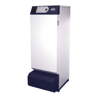
Summary of Contents for Delta FV 35
- Page 1 FV INSTALLATION OPERATING AND SERVICING INSTRUCTIONS NOTICE D’INSTALLATION, D’UTILISATION ET D’ENTRETIEN GEBRUIKSHANDLEIDING EN INSTALLATIEVOORSCHRIFT excellence in hot water 15/06/2004 - 664Y1600...
- Page 2 INSTALLATION OPERATING AND SERVICING INSTRUCTIONS delta FV 35 : With ACV BMV1 oil burner delta FV 50 : With ACV BMV2 oil burner NOTICE D’INSTALLATION, D’UTILISATION ET D’ENTRETIEN delta FV 35 : Avec brûleur fioul ACV BMV1 delta FV 50 : Avec brûleur fioul ACV BMV2...
- Page 3 N T1 T2 S3 B4 N T1 T2 SQK 349 N T1 T2 QAAD50 (QAAD70) QAC32 QAD22 bl bk br 19 18 17 16 15 14 13 12 11 10 230V-50 Hz 19 18 17 16 15 14 13 12 11 10...
- Page 5 B 23 C 13 / C 33...
- Page 6 12 11 3 N 8 4 10 1 B4 S3 T2 T1 N B4 S3 T2 T1 N...
-
Page 7: Oil Burner
INSTALLATION, OPERATING AND SERVICING INSTRUCTIONS performance balanced flue FV 35 with ACV BMV(K)1 oil burner FV 50 with ACV BMV(K)2 oil burner... -
Page 8: Applicable Standards
INDEX INTRODUCTION INTRODUCTION INTENDED USERS OF THESE INSTRUCTIONS Intended users of these instructions These instructions are intended for: Symbols - specifying engineers Applicable standards - installing engineers Warnings - users - servicing technicians DESCRIPTION SYMBOLS Overview Description of operation The following symbols are used in these instructions: Construction features Boiler captions Essential instruction for operating the system... -
Page 9: Description Of Operation
CFCs. • The Delta Performance FV 35 with a fixed output of 35 is fitted with the ACV BMV1 oil burner. Jacket The boiler is covered by a steel jacket which has been scoured and •... -
Page 10: Technical Specification
TECHNICAL SPECIFICATION GENERALE The units are delivered fully assembled, tested and packed on a timber base with shockproof edges and protected by heat-shrunk plastic film. On reception and after unpacking, check the equipment for damage. For transport purposes, refer to the weights and dimensions given below. MAXIMUM OPERATING CONDITIONS Maximum service pressure (tank full of water) -
Page 11: Domestic Hot Water Performance
TECHNICAL SPECIFICATION DOMESTIC HOT WATER PERFORMANCE FV/35 FV/50 Operating at 80 °C Peak delivery at 40 °C ( T = 30 °C) L/10’ Peak delivery at 40 °C ( T = 30 °C) L/60’ 1024 1485 Continuous delivery at 40 °C ( T = 30 °C) 1352 Tank refill time at 60 °C Initial heating time... -
Page 12: Installation
INSTALLATION BOILER ROOM Chimney connection type: B23 (See illustration L) The boiler is connected to the chimney by a metal pipe rising at an angle from the boiler to the chimney. Important • Keep vents free at all times. Un raccord de cheminée est nécessaire. •... -
Page 13: Heating Connection
INSTALLATION HEATING CONNECTION IMPORTANT As a safety measure against burns, we strongly recommend installing a thermostatic mixer. Example of a basic circuit configuration (see illustration G) 1. 3-way motorised mixing valve 2. Safety valve set to 3 bar with pressure gauge 3. -
Page 14: Electrical Connection
INSTALLATION ELECTRICAL CONNECTION OIL SUPPLY Power supply System construction and installation must be in accordance with DIN 4755. Local regulations must be followed. The boiler operates with a 230 V - 50 Hz single phase supply. An on-off mains switch box with 6 A fuses must be fitted outside the Oil pipes must be brought sufficiently close to the burner so that the boiler to allow power to be shut off during servicing and before any tubes can be connected without strain. -
Page 15: Burner Features
ACV BMV1 AND BMV2 BURNER CAPTIONS ACV BMV1 AND BMV2 OIL BURNERS (see illustration O) Description For the Delta Performance oil-fuelled balanced flue model, we have 1. Control unit opted for the all-new technology of the ACV BMV1 and BMV2 oil 2. Nozzle line protection burner, manufactured from high quality components combining 3. -
Page 16: Servicing The Safety Devices
STARTUP SERVICING FILLING THE DOMESTIC HOT WATER AND RECOMMENDATION HEATING CIRCUITS (see illustrations B, G et H) ACV advises that boilers should be serviced at least once a year. The burner must be serviced and tested by a competent engineer. SERVICING THE BOILER IMPORTANT (see illustration K) -
Page 17: Using The Boiler
USER GUIDE USING THE BOILER Safety valve (heating) If water flows from one of the safety valves, shut off the boiler and call your heating engineer. Have your system serviced every year by a qualified heating engineer. If the boiler is subject to heavy A monthly inspection is recommended: usage, it may need more frequent servicing. -
Page 18: Resetting Acv Bmv1 And Bmv2 Burners
USER GUIDE RESETTING ACV BMV1 AND BMV2 BURNERS (see illustration Q) If the burner is not working: 1. Remove the protective cover of the burner. 2. If the red light is lit, press the button to start the burner. 3. If the burner lights, replace the cover. If the burner does not operate, switch off the power before removing the front cover panel. - Page 19 REPLACEMENT PARTS / PIECES DETACHEES / WISSELSTUKKEN Codes Burner Brûleur Brander See Oil burner instructions Voir notice du brûleur fioul Zie handleiding van de stookoliebrander BMV(K)1 / BMV(K)2 BMV(K)1 / BMV(K)2 BMV(K)1 / BMV(K)2 Casing Jaquette Mantel Front panel Face avant Voorpaneel 21473397 Left panel...
- Page 20 excellence in hot water INTERNATIONAL FRANCE SLOVAK REPUBLIC ACV international n.v ACV FRANCE sa ACV SLOVAKIA s.r.o. KERKPLEIN, 39 31, RUE AMPERE - Z.I MI - PLAINE PLUHOVÁ 49 B-1601 RUISBROEK - BELGIUM F-69680 CHASSIEU - FRANCE 831 04 BRATISLAVA - SLOVAK REPUBLIC TEL.: +32 2 334 82 20 TEL.:+33 4 72 47 07 76 TEL.:+421 2 444 62 276...

Need help?
Do you have a question about the FV 35 and is the answer not in the manual?
Questions and answers