KERN EMB Service Manual
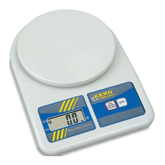
Emb series school balance
Hide thumbs
Also See for EMB:
- Operating instructions manual (17 pages) ,
- Operating instructions manual (12 pages) ,
- Operating instructions manual (18 pages)

Related Manuals for KERN EMB


Summary of Contents for KERN EMB
- Page 1 KERN & Sohn GmbH Ziegelei 1 Tel: +49-[0]7433- 9933-0 D-72336 Balingen Fax: +49-[0]7433-9933-149 E-Mail: info@kern-sohn.com Internet: www.kern-sohn.com Service manual School balance KERN EMB Version 3.3 4/2009 EMB-SH-e-0933...
-
Page 2: Table Of Contents
To Replace PCB ________________________________________________ 10 To Replace Load Cell Assembly ___________________________________ 11 10 Schematics ____________________________________________________ 12 10.1 For EMB 220-1, EMB 2200-0, EMB 5.2K5 ________________________________ 12 10.2 For EMB 500-1, EMB 1200-1, EMB 5.2K1 ________________________________ 13 10.3 For EMB 200-2, EMB 600-2 ___________________________________________ 14 10.4 For EMB 100-3, EMB 1000-2 __________________________________________ 15... -
Page 3: Basic Information
• Solder pads to prevent end-user internal calibration • Low battery indicator • Overload protection / indication • AC adaptable • Operated by 2 x AA size alkaline batteries (EMB220-1, EMB2200-0, EMB5.2K5), 9V battery (EMB100-3, EMB200-2, EMB600-2, EMB1000-2, EMB500-1, EMB1200-1, EMB5.2K1) EMB-SH-e-0933... -
Page 4: Calibration Procedure (Cal)
Wait until display shows [ F ] then turn off. In case [ E] is display instead of [ F], this indicates a calibration procedure error, unstable or wrong calibration weight applied for calibration. Turn the scale off and then on and repeat the procedure. EMB-SH-e-0933... -
Page 5: Internal Calibration Procedure (Linearity Adjustment)
100 000 to 300 000. In case out of this range, connect J9 (J4 for EMB 200-2 and EMB 600-2; J6 for EMB 100-3 and EMB 1000-2) left side or right side to increase or reduce the reading. Connecting or disconnecting pads on J6, J7 or J8 for EMB 220-1, EMB 2200-0, EMB 5.2K5... -
Page 6: Readout Of The Internal Counts
In that case the internal count is 321 580 5 Display Segment Test Whenever the scale is power on, all segments of the LCD will be turn on for approx. 5 seconds. Check for any missing segment. EMB-SH-e-0933... -
Page 7: Functional Block Diagram / Description
6 Functional Block Diagram / Description 6.1 Functional Block Diagram Keyboard L C D 9V/2xAA Battery Power control / Microprocessor Regulator & Low battery Adaptor detector digital signal Load cell Amplifier A/D Converter analog (Sensor) signal EMB-SH-e-0933... -
Page 8: Function Description
A low battery detector is employed to make sure that the power supply is strong enough for normal operation of the scale. 7. Keyboard The keyboard provides on user interface. [On/TARE], [OFF] keys are employed to operate the scale. EMB-SH-e-0933... -
Page 9: Trouble Shooting
If missing segments, check fixing of LCD frame, zebra connector under LCD. ↓ Display Zero? If display [LO], check battery >2.6v (>7.5v for EMB 100-3,EMB 200-2,EMB 600-2,EMB 500-1,EMB 1000-2, EMB 1200-1,EMB 5.2K1) adaptor>9v. If display [ E] , check internal count. -
Page 10: To Replace Pcb
8 To Replace PCB 1. Disassemble top housing of scale. 2. Disconnect PL1, SS1 and flat line of keyboard (EMB 220-1, EMB 2200-0, EMB 5.2K5) PL1, PL2 and PL3 (EMB 500-1, EMB 1200-1, EMB 5.2K1) PL1, PL2 and JP1 (EMB 200-2, EMB 600-2) PL1, PL3, JP2, J1 (flat line) and SENSOR (EMB 100-3, EMB 1000-2) from the PCB. -
Page 11: To Replace Load Cell Assembly
Connect the load cell wires and fix the screws. 3. Perform internal calibration as described in section 4. 4. Assemble the top housing. 5. Check accuracy of scale at different weight. EMB 200-2 EMB 600-2 EMB 220-1 EMB 500-1 weight tol. -
Page 12: Schematics
10 Schematics 10.1 For EMB 220-1, EMB 2200-0, EMB 5.2K5 EMB-SH-e-0933... -
Page 13: For Emb 500-1, Emb 1200-1, Emb 5.2K1
10.2 For EMB 500-1, EMB 1200-1, EMB 5.2K1 EMB-SH-e-0933... -
Page 14: For Emb 200-2, Emb 600-2
10.3 For EMB 200-2, EMB 600-2 EMB-SH-e-0933... -
Page 15: For Emb 100-3, Emb 1000-2
10.4 For EMB 100-3, EMB 1000-2 EMB-SH-e-0933... - Page 16 EMB-SH-e-0933 EMB-SH-e-0933...
-
Page 17: Components Layout
11 Components Layout 11.1 For EMB 220-1, EMB 2200-0, EMB 5.2K5 EMB-SH-e-0933... -
Page 18: For Emb 500-1, Emb 1200-1, Emb 5.2K1
11.2 For EMB 500-1, EMB 1200-1, EMB 5.2K1 EMB 500-1 EMB 1200-1 EMB 5.2K1 11.3 For EMB 200-2, EMB 600-2 EMB-SH-e-0933... -
Page 19: For Emb 100-3, Emb 1000-2
11.4 For EMB 100-3, EMB 1000-2 EMB-SH-e-0933... - Page 20 EMB-SH-e-0933...
Need help?
Do you have a question about the EMB and is the answer not in the manual?
Questions and answers