Advertisement
Quick Links
Advertisement

Related Manuals for Kärcher HD 7/250 DE TR1


Summary of Contents for Kärcher HD 7/250 DE TR1
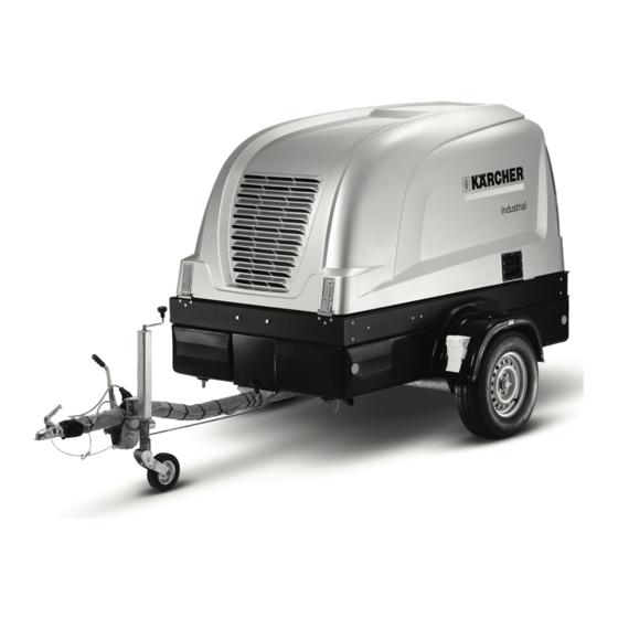
- Page 1 HD 7/250 De Tr1 59633200 08/10...
-
Page 3: Safety Instructions
Please read and comply with these original instructions prior to the initial operation of your appliance and store them for later use or subsequent own- ers. Contents Safety instructions EN - Function EN - Environmental protection EN - Proper use EN - Device elements EN -... - Page 4 Notes about the ingredients (REACH) You will find current information about the ingredients at: http://www.karcher.de/de/unternehmen/ umweltschutz/REACH.htm Proper use Use this appliance only as directed in these operating instructions. – The appliance is used to clean objects...
- Page 5 1 Towing hitch 2 Tear-off rope 3 Connector vehicle lighting 4 Support wheel 5 Battery 6 Battery main switch 7 Block wedge 8 Oil dip pump gear 9 Covering lid, oil drain opening pump gear 10 Oil drain screw intermediate gear 11 Oil sight glass intermediate gear 12 Ventilation screw intermediate gear 13 Ventilation end gear...
- Page 6 1 Display actual pressure 2 Bar graph fuel level 3 Bar graph water level in tank 4 Display cooling water temperature 5 Display oil pressure 6 F6 key, menu preselection Symbols on the display Symbol Meaning Nominal pressure Actual pressure Motor oil pressure Fuel level Water level in tank...
- Page 7 Operation Please observe Chapter "Safety Instruc- tions" and the enclosed safety instructions for high pressure cleaners (5.063-314.0) Transport Trailer operation Note The driver, who operates the towing vehicle with trailer on public roads must ensure that he has the appropriate license for this. Danger When transporting the trailer in public traffic with the water tank half full, the water can...
- Page 8 Caution Do not completely deplete the fuel in the fuel tank, otherwise, the fuel system will have to be ventilated. Possibly suctioned dirt from the bottom of the tank can lead to malfunctions. Check the fill level of the diesel fuel at the bar segment display for the fuel lev- el.
- Page 9 Connect the water supply hose to the respective water inlet (arrow). Open the lock on the appliance cover and swivel the appliance cover up- wards. Swivel the latch of the appliance hood upwards to keep it from shutting inad- vertently. Check the water filter for contamination, clean/replace if required.
- Page 10 Step 3: Press the F3 key to switch be- tween brightness and contrast. You can change the brightness and contrast levels with the F4 and F5 keys. F4 (-) = set value decreases. F5 (+) = set value increases. By pressing the F6 key twice, you will return to the operating display.
- Page 11 Refill the antifreeze container with anti- freeze. Select the mixing ratio of the water/antifreeze as per the instructions of the antifreeze manufacturer. Align the actuation lever of the ball tap for antifreeze/water tank vertically. Unscrew the high pressure hose from the high pressure outlet.
- Page 12 Maintenance and care Danger – Maintenance Procedures may only be carried out by persons who have been in- structed in the safe operation and mainte- nance on the high-pressure systems. – Before carrying out any tasks on the machine, switch the key switch off and remove it.
- Page 13 1 Compressor 2 Oil cooler module 3 Air cooler module 4 Cyclone separator 5 2/2 way solenoid valve, 2-stroke 6 Condensation drain, return to water tank 7 Pressure relief valve 8 Silencer 9 Backflow valve 10 Pressure regulation valve 11 Ball tap 12 Safety valve 13 Pressure container 14 Compressed air filter...
- Page 14 Time Activity Prior to each drive Check the lighting. Check the tyre pressure and their state. Every 10 operating Check oil level in the pump gear (see "Initial startup"), refill oil if needed. hours or daily Check the water filter and clean if necessary. Check coolant level in the equalisation container (see "Initial startup"), refill coolant if need- Once after the first 50 Replace motor oil (see "Maintenance Procedures").
- Page 15 Pump and gear Pump Mobil D.T.E Oil AA 320 Gear Mobil D.T.E Oil AA 320 The oil level is correct if it is within the markings on the oil dip. After the check, insert the oil dip and close the lid of the filler neck. Check the coolant and refill Note Prior to every operation, the fill level of the...
- Page 16 Faults Danger This can lead to severe injuries and possi- bly death. An improper startup and repair of the appliance and the spray unit is danger- ous. Faults with display Faults detected by the control are shown on the display. Display/meaning Cause Emergency Stop switch depressed...
- Page 17 Display/meaning Cause Cable plug of high pressure sensor loose or short in connection Cable breakage High pressure sensor defective >Malfunction< High pressure sen- The permitted max. pressure is exceeded due to small or plugged nozzle Load speed too high >Malfunction< High pressureHoch- druck >...
- Page 18 Ventilating the high pressure system Replace the valves Technical specifications (2001/14//EC) By whom Operator Operator Operator Operator Operator Customer Service HD 7/250 DE TR1 °C l/h (l/min) 1080 (18) MPa (bar) 0,15...0,6 (1,5...6) l/h (l/min) 672 (11,2) MPa (bar) 250 (2500) MPa (bar)
- Page 19 Accessories and Spare Parts – Only use accessories and spare parts which have been approved by the man- ufacturer. The exclusive use of original accessories and original spare parts ensures that the appliance can be oper- ated safely and troublefree. –...
- Page 20 KR Karcher Co. Ltd. (South Korea), 2nd Floor , Youngjae Building, 50-1, 51-1, Sansoo-dong, Mapo-ku, Seoul 121-060, +82-2-322 6598, www.karcher.co.kr MX Karcher México, SA de CV, Av. Gustavo Baz Sur No. 29-C, Col. Naucalpan Centro, Naucalpan, Edo. de México, C.P. 53000 México, +52-55-5357-04-28, www.karcher.com.mx...