
Related Manuals for TM RACING 2010 STROKE 250


Summary of Contents for TM RACING 2010 STROKE 250
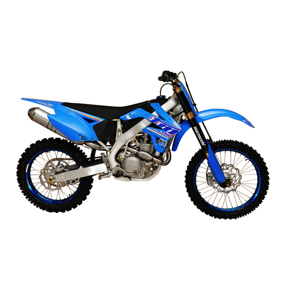
- Page 1 USER AND MAINTENANCE MANUAL TM 2 STROKE 2010 250/300 cc. TM RACING USES and ADVICES...
- Page 2 ENGLISH ENGLISH...
- Page 3 IMPORTANT YOU ARE ADVISED TO READ THIS MANUAL CAREFULLY BEFORE USING YOUR MOTO TM. IT CONTAINS A LOT OF INFORMATION AND ADVICE THAT WILL MAKE THE USE AND MAINTENANCE OF THE MOTORCYCLE MUCH EASIER AND SAFER. IT IS IN YOUR SPECIFIC INTEREST TO PAY PARTICULAR ATTENTION TO THE WARNINGS INDICATED IN THE FOLLOWING WAY: DANGER FAILURE TO COMPLY WITH THESE WARNINGS RISKS LIVES!
- Page 4 Always remember to respect the environment and other people. Always use the motorcycle with caution, it is in everybodys interest to safeguard the future of our sport. Enjoy yourself with your TM motorcycle! TM RACING S.p.A. Via Fano 6 - 61100 PESARO ITALY...
- Page 5 IMPORTANT ADVICE REGARDING THE LEGAL WARRANTY AND THE COMMERCIAL WARRANTY TM sport motorcycles are designed and constructed in a manner to support the stress that may be verified in normal road and competition use. Competition motorcycles are in compliance with the regulations of the categories actually in force at the most important international motorcycling federations.
-
Page 6: Table Of Contents
INDEX INDEX Page Page POSITION OF SERIAL NUMBER ........... 7 Adjustment of chain tension (SMM) ..........42 Frame number ................... 8 Chain maintenance ................42 Engine number ................... 8 Chain wear ..................43 OPERATING CONTROLS ..............9 Basic indications for TM disc brakes ..........43 Clutch lever AJP pump .............. -
Page 7: Position Of Serial Number
POSITION POSITION OF SERIAL OF SERIAL NUMBER NUMBER ENGLISH ENGLISH... -
Page 8: Frame Number
POSITION OF SERIAL NUMBER POSITION OF SERIAL NUMBER FRAME NUMBER The frame number is embossed on the right side of the steering metal tube. Make note of this number in the appropriate space on page 3. In the END, SMR, SMM models, the serial number is also stated on a plate positioned on the left hand side. -
Page 9: Operating Controls
OPERATING OPERATING CONTROLS CONTROLS ENGLISH ENGLISH... -
Page 10: Clutch Lever Ajp Pump
OPERATING CONTROLS OPERATING CONTROLS CLUTCH LEVER AJP PUMP The clutch lever (1) is mounted on the left of the handlebar. The position of the clutch lever, with respect to the handlebar grip, can be varied using the adjustment screws (A) (see maintenace operation). The adjusting screws (B) are used to adjust the pump after having adju- sted the lever position and to ensure the correct freeplay. -
Page 11: Electronic Digital Tachometer
OPERATING CONTROLS OPERATING CONTROLS ELECTRONIC DIGITAL TACHOMETER See picture (1). It is used on the END/SMR/SMM models. has a wide backlit display and four pilot lights. In the top there are the left indicator pilot light (2) , the low beam pilot light (3), the high beam pilot light (4) and the right indicator pilot light (5). -
Page 12: Combination Switch (End/Smr/Smm)
OPERATING CONTROLS OPERATING CONTROLS COMBINATION SWITCH WITH BACKLIT DIGITAL ELECTRONIC SPEEDOMETER (END/SMR/SMM) This command (1) is located near the handlebar left grip. The use of the switch is very easy. When the symbol (3) on the rotating ring is aligned with the symbol (4) on the switch body, lights are switched off. -
Page 13: Fuel Filler Cap
OPERATING CONTROLS OPERATING CONTROLS FUEL FILLER CAP The fuel fill cap is found on top of the tank. Open: turn the cap in an anti-clockwise direction Close: place the cap on the inlet well and tighten it in a clockwise di- rection. -
Page 14: Gear Shift Pedal
OPERATING CONTROLS OPERATING CONTROLS GEAR SHIFT PEDAL The gear shift pedal is positioned on the engine left side. The position of the gears is indicated in the illustration. The neutral is between the first and second gears. KICKSTART PEDAL The kickstart pedal is positioned on the right side of the engine. The upper part is turned outwards to start-up the engine and replaced inside as soon as the engine is running. -
Page 15: Side Stand Fixing For Offroad Routes
OPERATING CONTROLS OPERATING CONTROLS SIDE STAND FIXING FOR OFFROAD ROUTES If you drive the motorcycle off-road, the closed side stand can be addi- tionally fixed using a rubber band (2). IGNITION SWITCH In the SMR and SMM models an ignition key is added on the left side of the dashboard. -
Page 16: Fork Adjustment In Rebound
OPERATING CONTROLS OPERATING CONTROLS FORK ADJUSTMENT IN REBOUND The hydraulic dampening in extension determines the behaviour of the fork in the rebound stroke. The degree of dampening in rebound can be adjusted on the basis of pilot preferences and/or hardness of the spring installed. MARZOCCHI USD FORK The adjustment screw is located in the lower part of the fork leg (8). -
Page 17: Shock Absorber Adjustment In Rebound
OPERATING CONTROLS OPERATING CONTROLS Low speeds- The adjustment screw (1) is on the top of the damper gas tank. Use a screwdriver. By turning the screw clockwise, dampening increases, anticlockwise dampening decreases. A total of 25 clicks are available. High speeds- The adjuster is a hexagonal ring nut (2) and is concentric to the low speeds adjustment screw. -
Page 18: Steering Lock
OPERATING CONTROLS OPERATING CONTROLS STEERING LOCK This lock is situated on the left side of the frame steering tube. This lock stops rotation of the handlebar, preventing the motorcycle being driven. To lock the steering, turn the handlebar completely to the right, insert the key, turn it to the left, press, turn to the right and extract. -
Page 19: Advice And General Recommendations For Commissioning The Motorcycle
ADVICE AND ADVICE AND GENERAL GENERAL RECOMMENDATIONS RECOMMENDATIONS FOR COMMISSIONING FOR COMMISSIONING THE MOTORCYCLE THE MOTORCYCLE ENGLISH ENGLISH... -
Page 20: Indications For First Start-Up
ADVICE AND GENERAL RECCOMANDATIONS FOR ADVICE AND GENERAL RECCOMANDATIONS FOR COMMISSIONING THE MOTORCYCLE COMMISSIONING THE MOTORCYCLE DANGER INDICATIONS FOR FIRST START-UP - ALWAYS WEAR SUITABLE CLOTHING WHEN USING THE MOTOR- CYCLE. ASTUTE MOTORCYCLISTS THAT DRIVE A TM ALWAYS - Ensure that the “PRE-DELIVERY OPERATIONS” of your mo- WEAR THE TYPE-APPROVED HELMET, BOOTS, GLOVES AND torcycle have been carried out by your TM dealer. -
Page 21: Instructions For Use
INSTRUCTIONS INSTRUCTIONS FOR USE FOR USE ENGLISH ENGLISH... -
Page 22: Check Before Every Start-Up
INSTRUCTIONS FOR USE INSTRUCTIONS FOR USE CHECK BEFORE EVERY START-UP To use the motorcycle safely, it must be in a good shape. It is a good idea to carry out a general check-up of the motorcycle before every start-up. This check must include the following operations: 1 LEVEL OF ENGINE OIL To ensure adequate lubrication, the level of the oil in the engine must be kept within the envisioned limits. -
Page 23: Cold Engine Start
INSTRUCTIONS FOR USE INSTRUCTIONS FOR USE COLD ENGINE START 1 Open the fuel tap (1). 2 Remove the motorcycle from the stand. 3 Put the gears in neutral. 4 Activate the choke command (2), which is located on the left side of the carburetor. -
Page 24: If The Engine Is "Flooded
INSTRUCTIONS FOR USE INSTRUCTIONS FOR USE IF THE ENGINE IS “FLOODED” In the event of a fall, a certain amount of fuel can flow out the carburetor and enter the cylinder, “flooding” the engine. To start the engine, pull out the plug cap assy , unscrew the spark plug and extract it, then press the kick start pedal several times firmly DOWN TO THE BOTTOM. - Page 25 INSTRUCTIONS FOR USE INSTRUCTIONS FOR USE INDICATION: All TM models do not have a radiator cooling fan and the radiator di- mensions have been studied to optimise compactness and weight. The cooling system is sufficient for touristic or sports use. If you want to use an additional cooling fan contact a TM authorised dealer.
-
Page 26: Braking
INSTRUCTIONS FOR USE INSTRUCTIONS FOR USE BRAKING Close the throttle and brake at the same time progressively with the front and rear brakes. Insert a lower gear depending on speed. On dusty, wet or slippery surfaces, operate the brakes and change down the gears gently without locking the wheels. -
Page 27: Fuel
INSTRUCTIONS FOR USE INSTRUCTIONS FOR USE INDICATIONS REGARDING THE SIDE STAND: Push the stand forward until it stops and lean the motorcycle on it. Ensure that the ground is solid and the parking position is stable. For greater safety insert the 1st gear. WARNING THE SIDE STAND IS DESIGNED ONLY FOR THE WEIGHT OF THE MO- TORCYCLE. - Page 28 ENGLISH ENGLISH...
-
Page 29: Maintenance And Lubrication Table
MAINTENANCE MAINTENANCE LUBRICATION LUBRICATION TABLE TABLE ENGLISH ENGLISH... - Page 30 MAINTENANCE AND LUBRICATION TABLE MAINTENANCE AND LUBRICATION TABLE MAINTENANCE AND LUBRICATION TABLEE MAINTENANCE AND LUBRICATION TABLEE 250/300 END/SMR/SMM 250/300 END/SMR/SMM ROAD/HOBBY USE ROAD/HOBBY USE 1ST SERVICE EVERY 30 HOURS AFTER 3 HOURS A CLEAN VEHICLE PERMITS qUICKER AND THEREFORE CHEAPER INSPECTIONS 150 LT.
- Page 31 MAINTENANCE AND LUBRICATION TABLE MAINTENANCE AND LUBRICATION TABLE MAINTENANCE AND LUBRICATION TABLE MAINTENANCE AND LUBRICATION TABLE 250/300 MX/END/SMX COMPETITION USE 250/300 MX/END/SMX COMPETITION USE 1ST SERVICE AFTER 2 HOURS A CLEAN VEHICLE PERMITS qUICKER AND THEREFORE CHEAPER INSPECTIONS EVERY COMPETITION 12 LT.
- Page 32 MAINTENANCE AND LUBRICATION TABLE MAINTENANCE AND LUBRICATION TABLE BRIEF CHECK AND MAINTENANCE OPERATIONS TO BE PERFORMED BY THE RIDER/PILOT BRIEF CHECK AND MAINTENANCE OPERATIONS TO BE PERFORMED BY THE RIDER/PILOT AFTER BEFORE EVERY AFTER EVERY OFF-THE-ROAD START UP WASH • Check engine oil level •...
- Page 33 MAINTENANCE AND LUBRICATION TABLE MAINTENANCE AND LUBRICATION TABLE CHECKS TO BE CARRIED OUT ON ENGINE 250/300 END/MX/SMX CHECKS TO BE CARRIED OUT ON ENGINE 250/300 END/MX/SMX COMPETITION USE COMPETITION USE 15 HOURS OF SERVICE EqUAL ABOUT 150 LT. HOURS HOURS HOURS HOURS HOURS...
- Page 34 ENGLISH ENGLISH...
-
Page 35: Frame And Engine Maintenance
FRAME AND FRAME AND ENGINE ENGINE MAINTENANCE MAINTENANCE ENGLISH ENGLISH... -
Page 36: Check Steering Bearings And Play Adjustment
FRAME AND ENGINE MAINTENANCE FRAME AND ENGINE MAINTENANCE DANGER ALL MAINTENANCE AND ADJUSTMENT OPERATIONS THAT ARE MARKED WITH (A) REQUIRE TECHNICAL MASTERY. FOR THIS REASON IT IS IN THE INTEREST OF YOUR SAFETY TO HAVE THESE OPERATIONS CARRIED OUT EXCLUSIVELEY BY A SPECIALISED TM WORKSHOP WHERE YOUR MOTORCYCLE WILL BE MAINTAINED IN AN OPTIMAL MANNER BY SPECIFICALLY TRAINED STAFF. -
Page 37: Telescopic Fork Vent Screws
FRAME AND ENGINE MAINTENANCE FRAME AND ENGINE MAINTENANCE TELESCOPIC FORK VENT SCREWS Every 5 hours of use in competitions loosen the vent screws (1) by a few turns, so allowing the release of any air-pressure from inside the fork. Instead of a screw, Marzocchi fork features a tyre valve (3), which is protected by a rubber bulb (4). -
Page 38: Basic Calibration Of The Chassis On The Basis Of Pilot Weight
FRAME AND ENGINE MAINTENANCE FRAME AND ENGINE MAINTENANCE BASIC CALIBRATION OF THE CYCLE PART ON THE BASIS OF THE PILOT’S WEIGHT To obtain optimal driving features of the motorcycle and to prevent dama- ge to the fork, rear shock, rear swing arm and frame, it is necessary that the basic calibration of the suspension is adapted to your body weight. -
Page 39: Establishing Rear Shock Lowering In Running Order
FRAME AND ENGINE MAINTENANCE FRAME AND ENGINE MAINTENANCE ESTABLISHING REAR SHOCK LOWERING IN RUNNING ORDER - Now, with the help of a person who holds the motorcycle, sit on the motorcycle wearing all protective clothing (with feet on the footrests) and rock up and down a few times to normalise the set-up of the rear suspension. -
Page 40: Replacement Of Fork Springs
FRAME AND ENGINE MAINTENANCE FRAME AND ENGINE MAINTENANCE REPLACEMENT OF FORK SPRINGS If your body weight is less than 70 kg or exceeds 80 kg, adequate fork springs must be used. If you are in doubt or have any questions, please contact your authorised TM dealer. -
Page 41: Check Chain Tension
FRAME AND ENGINE MAINTENANCE FRAME AND ENGINE MAINTENANCE CHECK CHAIN TENSION Put the motorcycle onto the central stand to control chain tension. Push the chain upwards to the end of the drive chain slider. The upper part of the chain (A) must be taught (see photo). The distance between the chain and rear fork must be about. -
Page 42: Adjustment Of Chain Tension (Smm)
FRAME AND ENGINE MAINTENANCE FRAME AND ENGINE MAINTENANCE ADJUSTMENT OF CHAIN TENSION (SMM) Loosen both the locking screws(7) of the rear eccentric hub in a way that the hub itself can turn around its axis. Using the relevant TM tool, code F50806 (8), turn the hub until correct chain tension is reached. -
Page 43: Chain Wear
FRAME AND ENGINE MAINTENANCE FRAME AND ENGINE MAINTENANCE CHAIN WEAR To check chain wear follow carefully the instructions given below : put the gear into neutral, pull the upper part of the chain in an upward direction with a force of 10 - 15 kilogrammes (see figure). Now, measure the distance of 18 links on the lower part of the chain. -
Page 44: Front Brake Nissin Pump (End/Mx)
FRAME AND ENGINE MAINTENANCE FRAME AND ENGINE MAINTENANCE BRAKE FLUID RESERVOIRS: The front and rear brake liquid reservoirs are dimensioned in a way that topping-up is not necessary even if the brake pads are worn. In fact, when the pads are worn, the fluid in the hoses tends to occupy the space left by the small pistons, which have moved so that the pads always lay on the disc. -
Page 45: Front Brake Brembo Radial Pump (Smr/Smm/Smx)
FRAME AND ENGINE MAINTENANCE FRAME AND ENGINE MAINTENANCE WARNING - DO NOT ALLOW BRAKE FLUID TO COME INTO CONTACT WITH PAINTED PARTS, THE BRAKE FLUID CORRODES PAINT. - USE ONLY CLEAN BRAKE FLUID OUT OF A HERMETICALLY SEALED CONTAINER. FRONT BRAKE BREMBO RADIAL PUMP (SMR/SMM/SMX) FRONT BRAKE LEVER ADJUSTMENT The distance of the front brake lever from the handlebar grip can be adju-... -
Page 46: Replacement Of Front Brake Pads
FRAME AND ENGINE MAINTENANCE FRAME AND ENGINE MAINTENANCE REPLACEMENT OF FRONT BRAKE PADS (A) FOR ALL MODELS WITH FLOATING CALIPER (END/MX) Push the brake caliper towards the disc, in a way that the brake pistons reach their base position. Remove the safety devices (1), extract the pin (2) and remove the pads from the caliper. -
Page 47: Modification Of Rear Brake Pedal Base Position
FRAME AND ENGINE MAINTENANCE FRAME AND ENGINE MAINTENANCE MODIFICATION OF REAR BRAKE PEDAL BASE POSITION (A) The base position of the rear brake pedal can be modified in the following way: loosen counter-nut M6 (1) fork side, turn the adjustment screws by acting on the hexagonal head (2). -
Page 48: Check Rear Brake Pads
FRAME AND ENGINE MAINTENANCE FRAME AND ENGINE MAINTENANCE CHECK REAR BRAKE PADS The brake pads must be controlled from the rear side. The thickness of the pad friction material must not be less than 1 mm. DANGER AT THE THINNEST POINT, THE THICKNESS OF THE BRAKE PAD FRICTION MATERIAL MUST NOT BE LESS THAN 1 MM, OTHERWISE A FAULT COULD OCCUR IN THE BRAKES. -
Page 49: Disassembly And Assembly Of The Rear Wheel (All Except Smm)
FRAME AND ENGINE MAINTENANCE FRAME AND ENGINE MAINTENANCE WARNING - NEVER ACTIVATE THE BRAKE LEVER WHEN THE FRONT WHEEL IS DISASSEMBLED - ALWAYS POSITION THE WHEEL WITH THE BRAKE DISC UPWARDS TO PREVENT DAMAGE. To re-assemble the front wheel, insert it carefully into the fork, taking care to insert the disc correctly between the brake pads without damaging them. -
Page 50: Disassembly And Assembly Of Rear Wheel (Smm)
FRAME AND ENGINE MAINTENANCE FRAME AND ENGINE MAINTENANCE DISASSEMBLY AND ASSEMBLY OF REAR WHEEL (SMM) Rest the motorcycle with the frame cradle on a stand, in a way that the rear wheel does not touch the ground. Cut the safety binding (6), slide out the clasp (7) and unscrew the wheel nut M50x1.5(8). -
Page 51: Tyres, Tyre Pressure
FRAME AND ENGINE MAINTENANCE FRAME AND ENGINE MAINTENANCE TYRES, TYRE PRESSURE TYRE PRESSURE TYRE PRESSURE The type, the state and the pressure of the tyres condition the motor- FRONT REAR cycle’s behaviour on the road and they must be checked before every journey. -
Page 52: Battery
BATTERY (SMR E SMM) The saddle must be removed to access the battery. The battery does not require maintenance. It is not necessary to check the level of the electrolyte or top-up with water. The battery poles must be cleaned and, if necessary, slightly greased using grease that does not contain acids. -
Page 53: Standard Headlightd (End/Smr/Smm)
STANDARD HEADLIGHTD (END/SMR/SMM) REPLACEMENT OF HEADLIGHT/POSITION LIGHT BULB Release both elastic stripes and move the light-holder mask forward. NERO HEADLIGHT TWO-LIGHT BULB Disconnect the blue, black and white cables and remove the rubber protection (7). Release the retainer and carefully extract the bulb-holder (8). -
Page 54: Ciclops" Optional Headlight (End/Smr/Smm)
FRAME AND ENGINE MAINTENANCE FRAME AND ENGINE MAINTENANCE “CICLOPS” OPTIONAL HEADLIGHT (END/SMR/SMM) REPLACEMENT OF HEADLIGHT/POSITION LIGHT BULB Release both of the elastic stripes and move the light-holder mask forward. HEADLIGHT BULB Disconnect the terminal, remove the cover (4) and the seal (5). Unscrew the screws (6) and remove the retainer (7). -
Page 55: Led Rear Light
FRAME AND ENGINE MAINTENANCE FRAME AND ENGINE MAINTENANCE LED REAR LIGHT REPLACEMENT LED POSITION / STOP / NUMBER PLATE (END/SMR/SMM) Unscrew the screws (5) and remove the rear light body after disconnec- ting the wires from the bike harness. Since the led light is a single part, you have to change it completely. -
Page 56: Check Coolant Level
This mixture offers protection against freezing as well as a good protection against corrosion and therefore should not be replaced by pure water. WARNING - AFTER THE COOLANT LIQUID HAS BEEN EMPTIED, WHEN RE-FILLING IT IS NECEESARY TO BLEED THE COOLING SYSTEM (SEE NEXT PAGE). - ALWAYS USE GOOD QUALITY PRODUCTS TO PREVENT CORROSION OR FOAM. -
Page 57: Cleaning The Air Filter
FRAME AND ENGINE MAINTENANCE FRAME AND ENGINE MAINTENANCE DANGER WHEN THE ENGINE IS RUNNING THE EXHAUST SYSTEM BECOMES VERY HOT. ONLY START TO WORK ON THE EXHAUST SYSTEM WHEN IT HAS COOLED DOWN, TO PREVENT BURNS. To ease mounting of the silencer, grease the ends of the pipes. Also fix the retaining spring between the pipe and the silencer. -
Page 58: Hydraulic Clutch Brembo Pump
FRAME AND ENGINE MAINTENANCE FRAME AND ENGINE MAINTENANCE CHECK HYDRAULIC CLUTCH FLUID LEVEL The reservoir is part of the clutch pump positioned on the handlebar and has an inspection window: with the reservoir in a horizontal position, the level of the fluid must never fall below the centreline of the window, nor be above the upper margin. -
Page 59: Throttle Cable Command Adjustment
FRAME AND ENGINE MAINTENANCE FRAME AND ENGINE MAINTENANCE THROTTLE CABLE COMMAND ADJUSTMENT The throttle command should always have a free play of 3-5 mm. Mo- reover, when the engine is idling, the revs must not vary when steering as far as possible to the left and to the right. To adjust the play, push the protection hood backwards (6). -
Page 60: Basic Indications Regarding Carburetor Wear
FRAME AND ENGINE MAINTENANCE FRAME AND ENGINE MAINTENANCE BASIC INDICATIONS REGARDING CARBURETOR WEAR The throttle valve, jet needle and the float needle valve are subject to great wear caused by engine vibration. As a consequence the carbure- tor may malfunction (e.g. enrichening of the mixture). These parts must therefore be controlled after 200 hours. -
Page 61: Check Fuel Level (Float Height)
OPERATION WITH THROTTLE FULLY OPEN (MAX CAPACITY) If after a while at full gas the insulating part of a new plug (the ceramic part around the electrodes) appears particularly bright or white, you will need to replace the main jet with a richer one. If instead the insulating part of the plug appears dark or blackened, you will need to replace the main jet with a leaner one. -
Page 62: Check Engine Oil Level
FRAME AND ENGINE MAINTENANCE FRAME AND ENGINE MAINTENANCE CHECK ENGINE oIl lEvEl You should check the level of the engine oil with the engine at standstill but while it is still warm. Park the vehicle on level ground and keep it vertical (not on its side stand). -
Page 63: Change Engine Oil
FRAME AND ENGINE MAINTENANCE FRAME AND ENGINE MAINTENANCE CHANGE ENGINE OIL (A) WARNING WHEN CHANGING THE OIL, CLEAN THE MAGNET OF THE OIL DRAIN BOLT The oil must be changed with the engine at working temperature. DANGER THE ENGINE AT WORKING TEMPERATURE AND THE OIL INSIDE ARE VERY HOT - PAY ATTENTION, BURNS HAZARD. -
Page 64: Troubleshooting
TROUBLESHOOTING TROUBLESHOOTING If you have the envisioned maintenance operations carried out on your motorcycle, you will have very few problems. If, however, a problem does occur, please look for it in the following table and try to solve it. Please note that a lot of the operations cannot be carried out without the help of technicians . - Page 65 TROUBLESHOOTING TROUBLESHOOTING PROBLEM CAUSE SOLUTION Clogged idle speed jet Disassemble the carburetor and clean the jet THE ENGINE WILL NOT Altered idle speed adjustment screws Adjust the idle speed screws RUN AT IDLE SPEED Damaged spark plug Replace the spark plug Faulty Ignition system Have the ignition system checked The fuel overflows because the level is adjusted too...
-
Page 66: Cleaning
CLEANING CLEANING Clean the motorcycle regularly in a way to maintain the surface of the plastic parts in good condition. To do this, it is advised to use hot water with a detergent and sponge. Most of the dirt can be removed using weak water jets. WARNING NEVER CLEAN THE MOTORCYCLE WITH HIGH PRESSURE CLEANING DEVICES OR WITH STRONG JETS OF WATER! BECAUSE OF THE HIGH PRESSURE THE WATER COULD REACH THE ELECTRICAL PARTS, CONNECTORS, FLEXIBLE CABLE COMMANDS, BEARINGS, THE... -
Page 67: Technical Data - Engine
TECHNICAL DATA - ENGINE TECHNICAL DATA - ENGINE TECHNICAL DATA - ENGINE 250/300 MX 2010 TECHNICAL DATA - ENGINE 250/300 MX 2010 ENGINE 250 cc. 300 cc. Type 2 stroke single-cylinder DOHC , liquid cooled Displacement 249.3 cm 293.14 cm Cylinder bore and stroke 66.4x72 72x72... - Page 68 TECHNICAL DATA - ENGINE TECHNICAL DATA - ENGINE TECHNICAL DATA - ENGINE 250/300 END/SMX/SMR/SMM 2010 TECHNICAL DATA - ENGINE 250/300 END/SMX/SMR/SMM 2010 ENGINE SMR/SMM/SMX SMR/SMM/SMX Type 2 stroke single-cylinder DOHC , liquid cooled Displacement 249.3 cm 293.14 cm Cylinder bore and stroke 66.4x72 mm 72x72 mm Compression...
-
Page 69: Carburetor Settings
CARBURETOR SETTINGS CARBURETOR SETTINGS ENGLISH ENGLISH... -
Page 70: Engine Tightening Torques
ENGINE TIGHTENING TORqUES ENGINE TIGHTENING TORqUES 85-100 cc ENGINE TIGHTENING TORqUES 250/300 MX/END/SMR/SMM/SMX Crankase Allen screws, transmission cover, clutch cover, ignition cover 12 Nm Oil drain screw cap M14x1.5 20 Nm Oil filler screw cap M14x1.5 20 Nm Oil net filter screw cap 8 Nm Oil cartridge filter cover Allen screws 8 Nm... -
Page 71: Technical Data-Cycle Part
TECHNICAL DATA - CYCLE PART TECHNICAL DATA - CYCLE PART TECHNICAL DATA 250/300 MX/END/SMR/SMM/SMX TECHNICAL DATA 250/300 MX/END/SMR/SMM/SMX 250/300 MX 250/300 END 250/300 SMR/SMM Frame Twin-spar high resistance aluminium alloy frame Front suspension Marzocchi USD fork Rear/front suspension travel 300/315 mm Rear suspension Aluminium swing arm (Single-arm on SMM), Progressive mechanical linkage, Sachs shock (Ohlins optional) Front disc brake... -
Page 72: Alphabetic Index
ALPHABETIC INDEX ALPHABETIC INDEX Page Page Frame number ................... 8 Adjustment of chain tension (all models except SMM) ..... 41 Front brake BREMBO radial pump (SMR/SMM/SMX) ...... 45 Adjustment of chain tension (SMM) ..........42 Front brake lever BREMBO radial pump ..........10 ADVICE AND GENERAL RECOMMENDATIONS FOR Front brake lever NISSIN pump ............ -
Page 73: Wiring Diagrams
WIRING DIAGRAMS WIRING DIAGRAMS ENGLISH ENGLISH... - Page 74 ENGLISH ENGLISH...
- Page 75 ENGLISH ENGLISH...
- Page 76 ENGLISH 97047.10 TM-04 (ed. 03/10)
Need help?
Do you have a question about the 2010 STROKE 250 and is the answer not in the manual?
Questions and answers