Advertisement
Quick Links
WPR 2007
Wärmepumpen-
Regler
für Wärmepumpen mit
vereinfachter Regelung
(WPC) zum Heizen und
Kühlen
Bestell-Nr. / Order no. / N
Heat Pump
Controller
for heat pumps with
simplifi ed regulation
(HPC) for heating and
cooling
o
de commande : 452114.66.49
Montage- und
Inbetriebnahmeanweisung
für den Installateur
Installation and
Start-up Instructions
for Technicians
Notice de montage et
de mise en service
pour l'installateur
Régulateur de
pompe à chaleur
pour pompes à chaleur
à régulation simplifi ée
(WPC) pour chauff age et
rafraîchissement
FD 8709
Advertisement
Chapters

Subscribe to Our Youtube Channel
Related Manuals for Dimplex WPR 2007


Summary of Contents for Dimplex WPR 2007
- Page 1 WPR 2007 Montage- und Inbetriebnahmeanweisung für den Installateur Installation and Start-up Instructions for Technicians Notice de montage et de mise en service pour l‘installateur Wärmepumpen- Heat Pump Régulateur de Regler Controller pompe à chaleur für Wärmepumpen mit for heat pumps with pour pompes à...
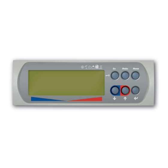
- Page 2 Einstellung der Sprache Instellen van de taal Bei Netzwiederkehr ist in der Displayanzeige die Auswahl Wanneer het net weer ter beschikking staat, kan in het der Sprache möglich. display de taal gekozen worden. Dazu die Taste ENTER (↵) betätigen und Druk hiervoor op de ENTER-toets (↵) en Gewünschte Sprache mit Pfeiltasten (⇑...
-
Page 3: Table Of Contents
Table of contents Table of contents 1 Important Information............................. E-2 2 Heat Pump Controller ............................. E-2 2.1 Heat pump controller: scope of supply............................E-2 3 Installation ............................... E-2 3.1 Attaching the wall-mounted heat pump controller ......................... E-2 3.2 Temperature sensor (heating controller N16) ..........................E-3 3.2.1 Mounting the external temperature sensor ........................... -
Page 4: Important Information
1 Important Information During start-up, observe the respective national safety To ensure that the antifreeze function of the heat pump regulations and the applicable VDE safety regulations, works properly, the heat pump controller must remain particularly VDE 0100 as well as the technical connection connected to the power supply and the flow must be requirements of the utility companies and network maintained through the heat pump at all times. -
Page 5: Temperature Sensor (Heating Controller N16
Installation 3.2 Temperature sensor (heating controller N16) All temperature sensors to be connected to the heat pump Depending on the connection type, the following additional controller have the sensor characteristic curve illustrated in Fig. temperature sensors must be installed: 3.3 on p. 3. The only exception is the external temperature External temperature sensor (Chap. -
Page 6: Electrical Connection Of The Heat Pump Controller To The Heat Pump
4 Electrical Connection of the Heat Pump Controller to the Heat Pump The supply cable for the output section of the heat pump The mixer (M21) is connected to X1/N. The mixer is must be routed as specified in the heat pump installation controlled by the HPC. - Page 7 Electrical Connection of the Heat Pump Controller to the Heat Pump Legends for Fig. 4.2 on p. 5 Contactor for flange heater K24 Relay for hot water request The utility bridge (J4/ID3-EVS to X2/0 V) must be inserted if no utility blocking contactor is fitted M14* Heat circulating pump (HC 1) (contact open = utility block).
-
Page 8: Preconfiguring The Heat Pump Heating System
5 Preconfiguring the Heat Pump Heating System The preconfiguration informs the controller about which corresponding setting ranges. Values in bold print indicate the components are connected to the heat pump heating system. factory settings. Preconfiguration must be carried out before the system-specific The factory settings in the “Preconfiguration”... -
Page 9: Configuring The Heat Pump Heating System
Configuring the Heat Pump Heating System 6 Configuring the Heat Pump Heating System The menus for “Outputs”, “Inputs” and “Special functions” as well simultaneously pressing the button combination (MENUE) and (ENTER ↵) (for approx. 5 seconds) as the extended setting menu can be set at the configuration level. - Page 10 Setting range Display System-specific parameters Different maximum temperatures are 25 °C Always permissible for panel and radiator heating ... 50 °C ... systems. The upper limit of the return set 70 °C temperature can be set between 25 °C and 70 °C.
- Page 11 Configuring the Heat Pump Heating System Setting range Display System-specific parameters Sets the desired return set temperature when 15 °C Heating circuit 2 fixed-setpoint regulation is selected ... 40 °C ... Fixed-setpoint 70 °C Parallel shift of the set heating curve for heating Indicator bar Heating circuit 2 circuit 2.
- Page 12 Setting range Display System-specific parameters For each day of the week, it is possible to select Cooling function whether Time1, Time2, no time or both times Dyn. cooling are to be active for a dynamic cooling block. Has the system got silent (dew point-controlled) Cooling function cooling? Sets the room set temperature for silent cooling...
-
Page 13: Outputs
Configuring the Heat Pump Heating System Setting range Display System-specific parameters Sets the start time for the thermal disinfection 00:00 Domestic hot water Sensor 23:59 Flange heater Sets the desired hot water temperature which is 60 °C Domestic hot water to be reached during thermal disinfection ... -
Page 14: Energy-Efficient Operation
7 Energy-efficient Operation If heating operation is carried out on the basis of the external Regulation via return temperature temperature, the heating controller calculates a return set Regulating a heat pump heating system via the return temperature from the set heating characteristic curve and the temperature offers the following advantages: current external temperature. -
Page 15: Setting Examples
Energy-efficient Operation 7.1.1 Setting examples Underfloor heating Radiators 35 °C/28 °C 55 °C/45 °C Standard external air temperature in °C Required flow temperature 35 °C 35 °C 35 °C 55 °C 55 °C 55 °C (at standard design temperature) 7 °C 7 °C 7 °C 10 °C... -
Page 16: Heating Curve Optimization
7.1.2 Heating curve optimization There are two setting options for optimizing the heating curve: Raising or lowering the entire heating curve by means of the buttons Hotter (⇑) and Colder (⇓) Changing the gradient by means of a higher or lower “Heating curve end point”... -
Page 17: Domestic Hot Water Preparation
Domestic Hot Water Preparation 10.1 8 Domestic Hot Water Preparation Hot water cylinders with a sufficient heat exchanger area should Regulation is carried out using a sensor installed in the hot water be used for DHW preparation. These must be capable of cylinder. -
Page 18: Activation Of Cooling Functions
10.2 10.1.2 Activation of cooling functions Special regulatory functions are performed when cooling Neither silent nor dynamic cooling was selected with “Yes” in operation is activated. the settings The cooling functions can fail to activate due to the following In all these cases, the cooling operating mode will remain active. reasons: However, the regulation system responds as in the summer operating mode. -
Page 19: Anhang / Appendix / Annexes
Anhang / Appendix / Annexes Anhang / Appendix / Annexes 1 Technische Geräteinformationen / Technical Device Information / Informations techniques sur les appareils ................................A-II 2 Hydraulische Einbindung / Hydraulic Integration / Intégration hydraulique..........A-II 2.1 Einbindungsschemen Heizen / Integration Diagrams for Heating / Schéma d’intégration chauffage .......... A-III 2.2 Einbindungsschemen Heizen/Kühlen / Integration Diagrams for Heating and Cooling / Schéma d’intégration chauffage/refroidisse- ment ...................................... -
Page 20: Technische Geräteinformationen / Technical Device Information / Informations Techniques Sur Les Appareils
1 Technische Geräteinformationen / Technical Device Information / Informations techniques sur les appareils 230 V AC 50 Hz Netzspannung Supply voltage Tension secteur 195 bis/to/à 253 V AC Spannungsbereich Voltage range Plage de tension etwa/approx./env. 50 VA Leistungsaufnahme Power consumption Puissance absorbée IP 20 Degree of protection according... -
Page 21: Einbindungsschemen Heizen / Integration Diagrams For Heating / Schéma D'intégration Chauffage
Hydraulische Einbindung / Hydraulic Integration / Intégration hydraulique 2.1 Einbindungsschemen Heizen / Integration Diagrams for Heating / Schéma d’intégration chauffage 2.1.1 Ein Heizkreis (1.HK) Heizen (Außentemperatur-/Raumtemperaturregelung) und Warmwasserbereitung / One heating circuit (HC1) for heating (external temperature / room temperature regulation) and domestic hot water preparation / Un circuit de chauffage (1er CC) avec chauffage (régulation de la température ambiante par la température extérieure) et production d’eau chaude sanitaire A-III... - Page 22 2.1.2 Zwei Heizkreise (1.HK/2.HK) Heizen (Außentemperatur-/Raumtemperaturregelung) und Warmwasserbereitung / Two heating circuits (HC1/HC2) for heating (external temperature / room temperature regulation) and domestic hot water preparation / Deux circuits de chauffage (1er et 2e CC) avec chauffage (régulation de la température ambiante par la température extérieure) et production d’eau chaude sanitaire A-IV...
-
Page 23: Einbindungsschemen Heizen/Kühlen / Integration Diagrams For Heating And Cooling / Schéma D'intégration Chauffage/Refroidissement
Hydraulische Einbindung / Hydraulic Integration / Intégration hydraulique 2.2 Einbindungsschemen Heizen/Kühlen / Integration Diagrams for Heating and Cooling / Schéma d’intégration chauffage/refroidissement 2.2.1 Ein Heizkreis (1.HK) Heizen (Außentemperatur-/Raumtemperaturregelung) und dynamisches Kühlen (Festwertregelung) / One heating circuit 1 (HC1) for heating (external temperature / room temperature regulation) and dynamic cooling (fixed- setpoint regulation) / Un circuit de chauffage (1er CC) avec chauffage (régulation de la température ambiante par la température extérieure) et rafraîchissement... - Page 24 2.2.2 Ein Heizkreis (1.HK) Heizen (Außentemperatur-/Raumtemperaturregelung) und stilles Kühlen (taupunktgeführte Regelung) / One heating circuit 1 (HC1) for heating (external temperature / room temperature regulation) and silent cooling (dew-point controlled regulation) / Un circuit de chauffage (1er CC) avec chauffage (régulation de la température ambiante par la température extérieure) et rafraîchissement passif (régulation en fonction du point de rosée) A-VI...
- Page 25 Hydraulische Einbindung / Hydraulic Integration / Intégration hydraulique 2.2.3 Zwei Heizkreise (1.HK/2.HK) Heizen (Außentemperatur-/Raumtemperaturregelung) und stilles oder dynamisches Kühlen (taupunktgeführte Regelung oder Festwertregelung) / Two heating circuits (HC1/HC2) for heating (external temperature / room temperature regulation) and silent or dynamic cooling (dew- point controlled regulation or fixed-setpoint regulation) / Deux circuits de chauffage (1er et 2e CC) avec chauffage (régulation de la température ambiante par la température extérieure) et rafraîchissement dynamique ou passif (régulation...
- Page 26 2.2.4 Zwei Heizkreise (1.HK/2.HK) Heizen (Außentemperatur-/Raumtemperaturregelung) und stilles oder dynamisches Kühlen (taupunktgeführte Regelung oder Festwertregelung) und Warmwasserbereitung über Thermostat / Two heating circuits (HC1/HC2) for heating (external temperature / room temperature regulation) and silent or dynamic cooling (dew-point controlled regulation or fixed-setpoint regulation) and domestic hot water preparation via thermostat / Deux circuits de chauffage (1er et 2e CC) avec chauffage (régulation de la température ambiante par la température extérieure), rafraîchissement dynamique...
-
Page 27: Legende / Legend / Légende
Hydraulische Einbindung / Hydraulic Integration / Intégration hydraulique 2.3 Legende / Legend / Légende Wärmepumpen Heat pumps Pompes à chaleur Wärmepumpenregler Heat pump controller Régulateur de pompe à chaleur Pufferspeicher Buffer tank Ballon tampon Warmwasserspeicher Hot water cylinder Préparateur d’eau chaude sanitaire Raumklimastation Room climate control station Sonde d’ambiance climatique... -
Page 28: Stromlaufpläne / Circuit Diagrams / Schémas Électriques
Gestionnaire de pompe à chaleur chauffage Abb. / Fig. / Fig. 3.1: Anschlussplan des wandmontierten Wärmepumpenmanagers WPR 2007 / Circuit diagram of the wall-mounted heat pump manager WPR 2007 / Schéma électrique du gestionnaire de pompe à chaleur mural WPR 2007... - Page 29 Stromlaufpläne / Circuit Diagrams / Schémas électriques 3.1.1 Anschluss externer Anlagenkomponenten / Connection of external system components / Branchement de composants d’installation externes 3.1.1.1 Eingänge / Inputs / Entrées Anschluss der Temperaturfühler am WPR / Connection of the temperature sensors to HPC / Connexion de la sonde de température au WPR WPR-Anschluss /...
- Page 30 3.1.1.2 Ausgänge / Outputs / Sorties Anschluss der WPC am WPR / Connection of HPC to HPC / Connexion du WPC au WPR WPR-Anschluss / WPC-Anschluss / Kommentar Comment Commentaire HPC connection / HPC connection / Connexion WPR Connexion WPC Spannung 230V AC Voltage 230 V AC Tension 230 V AC...
-
Page 31: Legende Zum Stromlaufplan Wärmepumpenregler Heizen/Kühlen / Legend For The Heat Pump Heating/Cooling Controller Circuit Diagram / Légende Du Schéma Électrique Du Régulateur De Pompe À Chaleur Chauffage/Rafraîchissement
Stromlaufpläne / Circuit Diagrams / Schémas électriques 3.2 Legende zum Stromlaufplan Wärmepumpenregler Heizen/Kühlen / Legend for the heat pump heating/cooling controller circuit diagram / Légende du schéma électrique du régulateur de pompe à chaleur chauffage/rafraîchissement Brücke EVS (J4/ID3-EVS nach X2/0V) The utility bridge (J4/ID3-EVS to X2/0 V) Pont de blocage du fournisseur muss eingelegt werden, wenn kein EVU-... -
Page 32: Diagnose Störungen - Alarm / Troubleshooting - Alarm / Diagnostic Défauts - Alarmes
R17* Raumtemperaturfühler Room temperature sensor Sonde de température ambiante Trafo Transformer Transfo Klemmenleiste Netz L/N/PE-230VAC/ Terminal strip for power supply L/N/PE- Bornier réseau L/N/PE-230 V AC/50 Hz 50Hz 230 V AC / 50 Hz Klemmenleiste interne Verdrahtung Terminal strip for internal wiring Bornier câblage interne 3-Wege-Umschaltventil für Three-way reversing valve for DHW... - Page 33 Garantiebedingungen Kundendienstadresse siehe Irrtümer und Änderungen vorbehalten. Montage- und Gebrauchsanweisung Wärmepumpe. Subject to alterations and errors. Sous réserve d’erreurs et modifications. For the terms of the guarantee and after-sales service addresses, please refer to the Installation and Operating Instructions for Heat Pumps. Pour les conditions de garantie et les adresses SAV, se référer aux instructions de montage et d'utilisation de la pompe à...
Need help?
Do you have a question about the WPR 2007 and is the answer not in the manual?
Questions and answers