
Related Manuals for Geutebruck GSD-682


Summary of Contents for Geutebruck GSD-682
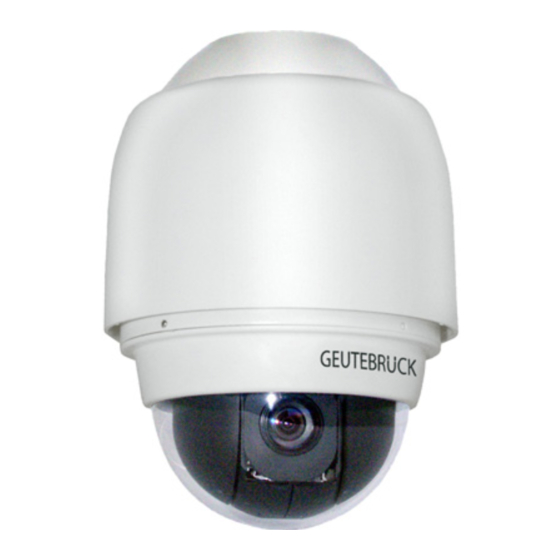
- Page 1 GSD-682 GSD-882 Integrierte High Speed Dome System Kameras Integrated High Speed Dome System Cameras Installationsanleitung Installation Manual...
- Page 3 Anwendungen konzipiert. Der GSD-882 kann bei Temperaturen zwischen -50 °C und +50 °C im Außenbereich der GSD-682 bei Temperaturen zwischen 0 °C und +45 °C im Innenbereich eingesetzt werden. Inhalt der Anleitung Dieses Manual gilt für beide Speed-Dome-Typen. Abweichungen bzgl. technischer Details, der Befestigung/Installation, usw., werden an den entsprechenden Stellen getrennt beschrieben.
- Page 4 Betreiben Sie die Dome - Kamera nur bei Temperaturen wie vor angegeben und einer relativen Luftfeuchtigkeit kleiner 90 % (nicht kondensierend). Der GSD-882 besitzt die Schutzklasse IP66 für den Außenbereich, der GSD-682 eignet sich AUSSCHLIESSLICH für Innenräume. • Montieren Sie das Dome System nur an einem geeigneten, stabilen und schwingungsfreien Montageort.
-
Page 5: Table Of Contents
1. Überblick ......................5 1.1 Besondere Produkteigenschaften ................6 1.2 Produkteinbindung ..................... 7 2. Installation / Inbetriebnahme GSD-882 / GSD-682 ......... 8 2.1 Installation / Inbetriebnahme des GSD-882 ............... 8 2.2 Lieferumfang GSD-882 ....................8 2.2.1 Dome Installation ....................9 2.3 Installation / Inbetriebnahme des GSD-682 .............. - Page 6 3.3.21 ZEITEINSTELLUNG (Uhrzeit/Datum-Funktion) ............ 52 3.3.22 ZEITPLAN (Termin/Zeitplanung) ................53 3.3.23 BEENDEN OSD ....................54 Anhang A: Technische Daten GSD-882 / GSD-682 ..........55 Steuerprotokolle JVC TK-C 676E (im Anhang d. engl. Manuals) Anhang B: Verfügbares Zubehör ................. 57 Netzteil PSU-24VAC/80VA/Boxed (5.14040) ..............57 Bracket Wall Mount GSD/BWM-003 (5.04802) ..............
-
Page 7: Überblick
1. Überblick Beide Speeddome-Typen beinhalten das gleiche Kamera-Zoomblock-Modul. Das integrierte High-Speed Dome-Kamera-Modul verfügt über die neueste Generation besonders leistungsfähiger DSP-Farbkameras, mit 36-fach optischem und 12-fachem Digital Zoom. Durch diese hohe Zoomfähigkeit erlaubt die Kamera einen klaren Blick, auch über große Distanzen. Ergänzt durch Auto-Fokus, Gegenlicht-Kompensation, automatische Belichtungsregelung AES, ausschwenkbares IR-Sperrfilter, Privacy Masking (ESF - elektronische Sichtschutzfunktion) und Weitdynamikbereich Wide Dynamic Range (WDR), wird so unter fast allen Umständen eine möglichst optimale Bildqualität erreicht. -
Page 8: Besondere Produkteigenschaften
1.1 Besondere Produkteigenschaften Präzise und genaue Objektverfolgung Automatischer Abgleich Positionsgenauigkeit für Schwenken und Neigen: +- 0.225° Geschwindigkeit beim Anlaufen von Festpositionen: bis zu 400°/s Die Schwenk-/Neigegeschwindigkeiten können proportional zur eingestellten Brennweite gewählt werden. Tag/Nacht-Umschaltung • Ausschwenkbares lR Sperrfilter Anwendungen bei schwacher Beleuchtung •... -
Page 9: Produkteinbindung
1.2 Produkteinbindung Das folgende Anschlussdiagramm zeigt die Einbindung der Dome - Kamera in ein Videoüberwachungssystem und die Verbindungsmöglichkeiten mit anderen Systemkomponenten. Achtung: Bei istanzen über 1200 m empfehlen wir dringend den Einsatz eines Repeaters. Dies erhöht zudem die Ausfallsicherheit im . -
Page 10: Installation / Inbetriebnahme Des Gsd-882
2. Installation / Inbetriebnahme des GSD-882 / GSD-682 Die nachfolgende Dokumentation beschreibt den Anschluss, die Einstellung und Bedienung der Dome - Kameras. Bitte beachten Sie, dass Sie zur Steuerung und Kontrolle der Hochgeschwindigkeitsdome grundsätzlich ein Bediengerät (z.B. GEUTEBRÜCK MBeg/GCT), bzw. Software (z. B. GscTelecontrol), benötigen. -
Page 11: Dome Installation
2.2.1 Dome Installation Auspacken und Bereitstellen der Dome - Kamerateile Drehen und Abnehmen der oberen Gehäusekappe. Evtl. vorher die Arretierschraube im Deckel lösen. Entfernen der Schutzabdeckung. Den Gummidichtring der unteren Domekuppel mit dem beigelegten Gleitmittel bestreichen. Das erleichtert die Montage der unteren Kuppel und vermeidet Beschädigungen des Dichtringes. - Page 12 Montage der unteren Kuppel. Bitte beachten Sie, dass die kleine Nase an der Kuppel mit einem der vier Löcher m Gehäuseteil übereinstimmt. Mit zwei Händen und leichtem Druck die Kuppel einsetzen. Vorher die kleine Nase in passendes Loch einhaken. Auf keinen Fall die Kuppel wie im Bild gezeigt einsetzen.
- Page 13 Mit der beigefügten Schraube fixieren Sie die obere Dome - Kamera bdeckung im Wandhalter. Einstecken des Kabels in die Dome - Kamera Montieren (Rechtsdrehung) und Verschrauben der oberen Dome - Kamera bdeckung. Fertig montierte Dome - Kamera GSD-882...
-
Page 14: Installation / Inbetriebnahme Des Gsd-682
2.3 Installation / Inbetriebnahme des GSD-682 Die nachfolgende Dokumentation beschreibt den Anschluss, die Einstellung und Bedienung der Dome - Kamera. Bitte beachten Sie, dass Sie zur Steuerung und Kontrolle des Hochgeschwindigkeitsdomes grundsätzlich ein Bediengerät (z. B. GEUTEBRÜCK MBeg/GCT) benötigen. 2.3.1 Lieferumfang Bitte prüfen Sie die Lieferung auf Vollständigkeit (siehe nachfolgende Liste). -
Page 15: Dome Installation
2.3.2 Dome Installation Je nach Installationsumgebung wird der Dome an der Decke oder Wand montiert. In den folgenden Abschnitten werden die unterschiedlichen Installationszubehöre und -arten im Detail beschrieben. 2.3.2.1 Deckenmontage Grundsätzlich gibt es drei Deckenmontagearten: Aufputzmontage, Deckeneinbau und Montage mit Abstandshalter (Abstandsrohr) Die folgenden Abbildungen zeigen die unterschiedlichen Kabelanschlussarten. - Page 16 Aufputzmontage Aufputzmontage ist die Standardinstallation für Innendome. Das hierfür notwendige Montagezubehör liegt der Domeverpackung bei. Die benötigten Zubehöre sind im folgenden Abschnitt gelistet. Benötigtes Material: Dome Kamera Aufputzmontagering und Zierring ( nthalten) Fixierungslasche ( nthalten) Beachten Sie die nachfolgenden Schritte für die Dome-Aufputzmontage. Achtung: Entfernen Sie vor der Montage die Domekuppel! Schritt 1...
- Page 17 Schritt 6 Ziehen Sie das kabel durch den Montagering und stecken Sie es in den vorgesehenen Domeanschluss. Schritt 7 Stecken Sie das Domegehäuse in den Montagering und drehen Sie ihn im Uhrzeigersinn bis zum Anschlag. Fixieren Sie das Domegehäuse durch Anziehen der Fixierungsschraube (s.
- Page 18 Deckeneinbaumontage Das hierfür notwendige Montagezubehör liegt den Verpackungen bei. Die benötigten Zubehöre sind im folgenden Abschnitt gelistet. Benötigtes Material: Dome Kamera T-Bar (Einbausatz, optionales Zubehör) Fixierschraube (Enthalten im Einbausatz) Montageschablone (Enthalten im Einbausatz) Zierring (enthalten in Domeverpackung) Beachten Sie die nachfolgenden Schritte für die Deckeneinbaumontage. Achtung: Entfernen Sie vor der Montage die Domekuppel! Schritt 1: Lösen Sie die markierte Fixierungs-...
- Page 19 Schritt 4 Platzieren Sie den Einbausatz in die vorgesehene Öffnung. Schritt 5 Drehen Sie die Befestigungsflügel um 180° Schritt 6 Ziehen Sie die 3 Schrauben (s. Abbildung) soweit an, bis der Einbausatz fest in der Öffnung sitzt. Schritt 7 Ziehen Sie das kabel durch den Montagering und stecken Sie es in den vorge-...
-
Page 20: Deckenmontage Mit Abstandsrohr
Befestigen Sie den Zierring 2.3.2.2 Deckenmontage mit Abstandsrohr Das Abstandsrohr ist in 2 Längen erhältlich: 25 cm und 50 cm. Benötigtes Material: Dome Kamera Abstandsrohr mit Zubehör (optional) Montageadapter und Zubehör (optional) Beachten Sie die nachfolgenden Schritte für die Deckeneinbaumontage. Achtung: Entfernen Sie vor der Montage die Domekuppel! 1) Stellen Sie sicher, dass die Decke ausreichend tragfähig ist. - Page 21 4) Ziehen Sie das Kabel durch das Abstandsrohr und den Montageadapter. Achtung: Ziehen Sie vor Montage des Adapters die Gummiabdeckung über das Abstandsrohr. 5) Verschrauben Sie den Montageadapter mit dem Abstandsrohr. 6) Schrauben Sie die Fixierungslasche auf das Domegehäuse, s. Abbildungen 7) Stecken Sie das kabel in den vorgesehenen Domeanschluss.
-
Page 22: Wandmontage Mit Wandhalter
4) Befestigen Sie den Dome und Montageadapter am Wandhalter und verfahren weiter wie unter Schritt 6 -9 der Deckenmontageanleitung mit Abstandsrohr. Bitte beachten Sie bei der Montage des GSD-682, dass dieser nur mit dem Domemontageadapter GSD/BDA-001 montiert werden kann. Bitte separat bestellen (5.04866) -
Page 23: Schalterbeschreibung Und Einstellung
2.4 Schalterbeschreibung und Einstellung Bevor Sie die Dome - Kamera mit anderen Geräten verbinden, ist es unerlässlich, die Dome ID (Adresse) und das Kommunikations-/Steuerprotokoll einzustellen. Die für die Einstellungen benötigten Schalter befinden sich im Unterteil der Dome - Kamera (s. Abbildung). Reserviert Kommunikationsschaltereinstellung Dome ID Einstellung... -
Page 24: Dome Id Einstellungen (Schalter C)
Bitte beachten Sie, dass beide Geräte die gleiche RS-485 Einstellung haben. Die RS-485 Default - Einstellung ist Halbduplex (s. nachfolgende Abbildung). RS-485 Schalter Halb-Duplex Voll-Duplex 2.6 Dome ID Einstellungen (Schalter C) Benutzen Sie die drei Schalter zur Einstellung der Dome - Kamera ID (Nummer der Kamera im Fernsteuerbus). -
Page 25: Dome - Kamera Fernsteuerprotokoll (Schalter D)
2.7 Dome - Kamera Fernsteuerprotokoll (Schalter D) Einstellung der Schalter D für das benötigte Fernsteuerprotokoll Wählen Sie das JVC/GEUTEBRÜCK Protokoll mit der Schalterstellung 20 und Baud Rate 9600, wie in der folgenden Abbildung dargestellt. Zehner Einheit Einer Einheit Schnittstellenparameter: 9600 Baud 8 Datenbits /1 Stoppbit Parity even Halb-Duplex / Kein Handshake... -
Page 26: 22-Polige Steckerbelegung
2.8 22-polige Steckerbelegung Der Dome-Kamera ist ein 22-poliges kabel mit 130 cm Länge zum vereinfachten Anschluss beigelegt. Die nachfolgenden Abbildungen und Tabellen zeigen die Pinbelegung des 22-poligen Steckers. VOR dem Anschluss unbedingt die Farben des beiliegenden Kabels prüfen! Funktion und Kennzeichnung der Anschlüsse: Funktion Farbe Kabel... -
Page 27: Alarm Kontakt Beschreibung
2.9 Alarm Kontakt Beschreibung Nachfolgend wird die Funktion und Pinbelegung für die Alarmkontakte in der 22-poligen Buchse im Unterteil der Dome - Kamera beschrieben. Kontakt Farbe Definition Weiss ALARM NORMAL OFFEN Schwarz/Weiss ALARM NORMAL GESCHLOSSEN ALARM Grün/Schwarz GEMEINSAMER Blau/Weiss ISOG Rot/Weiss ALARM-1 Violett... -
Page 28: Anschlussbeschreibung
2.10 RS-485 Anschlussbeschreibung Über die RS-485-Schnittstelle kommuniziert die Dome-Kamera mit dem Kontrollgerät. Bitte beachten Sie, dass beide Geräte die gleichen RS-485 Einstellungen haben. Das empfohlene Anschlusskabel für RS-485 Verbindungen ist CAT 5 Kabel. Die Kabellänge beträgt 1200 m. Bei Kabellängen über 1200m ist die Verwendung eines Repeaters notwendig. -
Page 29: Bedienung Und Einstellung
3. Bedienung und Einstellung der Kamera 3.1 OSD Menü Anzeigeformat Die dargestellten Informationen werden in der OSD- (On-Screen-Display) Menü- Baumstruktur beschrieben. Die Position auf dem Bildschirm und die Funktionsbe- schreibung entnehmen Sie der nachfolgenden Tabelle. Position Funktion OSD Anzeige Beschreibung ohne Funktion nicht enthalten Alarm... -
Page 30: Osd Menü Baumstruktur
3.2 OSD-Menü Baumstruktur Im nachfolgenden Abschnitt wird die OSD-Menü-Struktur und das Setup beschrieben. Der Stern steht für "Werkeinstellung". Die ausführliche Funktionsbeschreibung folgt in Abschnitt 4.3 Menüeinstellungen. Begriff Ebene 1 Ebene 2 Ebene 3 Werkeinst. <ENGLISCH>, <VEREINF. CHINES.>, <FRANZ.>, <DEUTSCH>, <ITAL>, <JAPANISCH>, <POLNISCH>, <PORTUG.>, SPRACHE ENGLISCH <RUSSISCH>, <SPANISCH>, <TUERKISCH>... - Page 31 BEENDEN ID ANZEIGE <AN>, <AUS> TITEL ANZEIGE <AN>, <AUS> TITEL EINST. <01> ~<16> VORG. SETZEN <001>~<256> EINGABE VORGABE VORG. START <001>~<256> EINGABE BEENDEN EINGABE SEQUENZ LINIE <1> ~<8> SEQUENZ <01> ~<32> PUNKT VORGABE. <001>~<255>, <ENDE> SEQUENZ GESCHW. <01>~<15> VERWEILZEIT <000>~<127>SEK. SEQ.
- Page 32 ERK. SCHALTER <AN>, <AUS> AN: <INT FOKUS>, <FIX FOKUS>, <FIX AE>, ERK. MODUS <BEWEGUNG>; AUS: KEIN BLOCK MODUS KEIN; BEWEGUNG: <AN>, <AUS> RAHMEN ALARMERK. KEIN; BEWEGUNG: <01> ~ <04> SETZEN RAHMEN DEAKT. KEIN; BEWEGUNG: <01> ~ <04> GRENZWERT KEIN; BEWEGUNG: <001> ~ <255> BEENDEN <AN>, <AUS>...
-
Page 33: Einstellungsmenü
3.3 Einstellungsmenü Die verfügbaren Funktionen und Parametereinstellungen Ihrer Hochgeschwindigkeits - Dome - Kamera werden mit einem Bediengerät über das OSD (On Screen Display)- Menü konfiguriert. Die einzelnen Elemente des OSD-Menüs werden in den folgenden Abschnitten beschrieben. HAUPTSEITE 1 HAUPTSEITE 2 SPRACHE DEUTSCH ID ANZEIGE... -
Page 34: Osd-Einstellung Via Gsctelecontrol
OSD-EINSTELLUNG via GscTelecontrol (nur im GscSetup möglich!) Um das OSD-Menü des Domes aufzurufen, drücken Sie den <CAMERA ON>-Button. Bewegen Sie mit dem Joystick den OSD-Cursor zum gewählten OSD - Menüpunkt. - Bei Menüpunkten mit einem Zeichen, bewegen Sie den Joystick nach links oder rechts, um die Funktion dieses Menüpunktes auszuwählen. -
Page 35: Ae Modus (Automatische Belichtungsregelung)
• AUTOMATISCH Die optimale Schärfe wird durch einen internen Regelkreis ständig optimiert. Hier gibt es drei Modi für unterschiedliche Bedingungen: Normaler AF-Modus (Autofokus): der Dome regelt den Fokus ständig nach. Zoom Trigger Modus: wenn die Brennweite verändert wird, regeIt der Dome den Fokus nach Beenden des Zooms nach (Werkeinstellung ist 5 Sek.). -
Page 36: Wbc Modus (Weißbalance)
• AGC (Automatische Verstärkungsregelung) Bei dieser Option wirkt zuerst die Verstärkungsregelung. Die AGC kann nur ausgeschaltet werden. Es wirken nur „BLENDE" und dann „VERSCHLUSS". Diese Einstellung ist empfehlenswert, wenn ein zu starkes Bildrauschen verhindert werden soll (ist jedoch mit Verlust an Lichtempfindlichkeit verbunden). •... -
Page 37: Einstellmenü 1
3.3.7 EINSTELLMENÜ 1 EINSTELLMENU 1 ZOOMGESCHW. DIGITALER ZOOM LANGSAME VERSCHLUSSZEIT BILDUMKEHRUNG STANDBILD BLENDENÖFFNUNG AUTO STABILIZER STABLE ZOOM BEENDEN • ZOOMGESCHWINDIGKEIT Der Bediener kann eine gewünschte Zoomgeschwindigkeit einstellen zwischen 8 (Werkeinstellung = schnell) und 1 (langsam). • DIGITALER ZOOM Der Digital Zoom ist max. 12-fach. Nach Erreichen der längsten optischen Brennweite läuft der digitale Zoom bis zum maximalen Wert weiter. -
Page 38: Bildumkehrung
• BILDUMKEHRUNG (z. B. für Demozwecke > Dome STEHT) Wählen Sie die Option <AN> wenn Sie das dargestellte Bild horizontal und vertikal spiegeln möchten (siehe Darstellungen unten). Privacy Masking wird in diesem Fall deaktiviert! Die Werkeinstellung ist <AUS>. BILDUMKEHRUNG (AUS) BILDUMKEHRUNG (AN) •... -
Page 39: Einstellmenü 2
3.3.8 EINSTELLMENÜ 2 EINSTELLMENÜ 2 DREHEN ENTER WINKELJUSTIERUNG ENTER GESCHW. PRO ZOOM AUTOM. KALIBRIERUNG PASSWORT SYSTEM RESET SCAN MODE BEENDEN • DREHEN (FLIP/elektronische oder mechanische Bildumkehr) Achtung! Wenn die Bildumkehr aktiv ist, wird automatisch die Privacy Masking Funktion deaktiviert! Der Beobachter kann ein Objekt kontinuierlich verfolgen, auch wenn es sich unter der Kamera hindurch bewegt. -
Page 40: Winkeljustierung (Min/Max)
• WINKELJUSTIERUNG (Min/Max) Mit dieser Einstellung ist es möglich auch Objekte zu sehen, die sich bis zu 10° oberhalb horizontalen Blickrichtung (+/-10 ) befinden. Maximum der Auslenkung ist wie folgt einstellbar: WINKELJUSTIERUNG MIN WINKEL -10° MAX WINKEL 100° BEENDEN + SPEICHERN •... -
Page 41: Id Anzeige
3.3.9 ID ANZEIGE Diese Funktion erlaubt Ihnen die Einblendung der ID-Nummer zur Identifizierung der Dome - Kamera. Gehen Sie mit dem Joystick im <HAUPTMENÜ> zur Seite 2 und wählen den Menüpunkt <ID ANZEIGE>. Weitere Informationen zur Dome ID finden Sie im Abschnitt 2.4 Dome ID Einstellungen. -
Page 42: Vorgabe Festpositionen
Beispiel: A "ENTER", B "ENTER", C "ENTER". Als Titel erhalten Sie: ABC Schritt 6: Um einen Buchstaben zu löschen, bewegen Sie den Cursor auf den Buchstaben und drücken <ENTER>, dann auf <LÖSCHEN> und ebenfalls <ENTER>. Schritt 7: Bewegen Sie den Cursor auf <SPEICHERN> und drücken <ENTER> um die Einstellungen zu speichern. -
Page 43: Automatisches Schwenken
• VORGABE POSITION Hier können die gewünschten Festpositionen (wenn nicht schon geschehen) programmiert werden. "BEENDEN" wird benötigt , wenn weniger als 32 Positionen in der Sequenz angefahren werden sollen. Dies bedeutet, dass z. B. bei nur 5 in der Sequenz verwendeten Positionen die Festpos. - Page 44 Achtung: Die Neige- und Zoom-Werte werden aufgezeichnet und gelten für den gewählten automatischen Schwenkablauf. • ENDPUNKT Endposition für den Autopanablauf. >FINDEN<: Durch Drücken von <ENTER> gelangt man in den Joystick-Modus. Mit dem Joystick kann dann die gewünschte Position eingestellt werden. >SPEICHERN<: Durch Drücken von <ENTER>...
-
Page 45: Kamerafahrt
3.3.15 KAMERAFAHRT Es können vier Touren (KAMERAFAHRT) programmiert werden. Hierbei werden die Joystickkommandos, die Geschwindigkeit und die Zeit aufgezeichnet. Die Tour kann einen beliebigen Verlauf haben. Es können auch Haltepunkte enthalten sein. KAMERAFAHRT KAMERAFAHRTLINIE ENTER AUFZEICHNUNG START ENTER AUFZEICHNUNG ENDE KAMERAFAHRT AUSFÜHREN ENTER BEENDEN •... -
Page 46: Ir Funktion (Zuschaltbarer Ir Cut Filter)
• AUSWAHL MODUS (AUTOM. SCHWENKEN/SEQUENZ/KAMERAFAHRT/VORGABE) Die Kamera führt die hier gewählte Funktion aus, wenn <STARTFUNKTION> eingeschaltet und die <RÜCKKEHRZEIT> abgelaufen ist. • VORGABEPUNKT Geben Sie eine Position ein (1 - 256), die in der STARTPOSITION angefahren werden soll. SEQUENZ LINIE Geben Sie eine Sequenz ein (1 - 8), die in der STARTPOSITION ausgeführt werden soll. - Page 47 3.3.17 IR FUNKTION (schwenkbarer IR Cut Filter) Hier wird eingestellt, wie die Farbe/SW-Funktion und das motorisch betriebene IR-Sperrfilter arbeiten soll. • AUTOM. Die Umschaltung zwischen Farbe und SW findet automatisch statt. Bei SW wird das IR- Sperrfilter aus dem Strahlengang gefahren und die Farbmodulation im Signal (nicht der Farbhilfsträger!) abgeschaltet.
-
Page 48: Alarmeinstellung
3.3.18 ALARMEINSTELLUNG Beide Dome stellen 7 + 1* Alarmeingänge (N.O./Normal Offen oder N.C./Normal Geschlossen) und einen Alarmausgang zum Anschluss von Alarmgeräten bereit. Mit dieser Funktion kann der Dome mit einem Alarmsystem kooperieren und z.B. Ereignis-/Alarmbilder liefern. In diesem Menü werden die Alarmparameter eingestellt. ALARMEINSTELLUNG ALARMKONTAKT ALARMSCHALTER... - Page 49 • ALARMAKTION Hier wird ausgewählt, welche Funktion bei Eingang eines Alarms ausgeführt werden soll. Es gibt vier Möglichkeiten. 1. Die Kamera läuft in eine von 256 programmierten Positionen. 2. Es wird eine von acht Sequenzen gestartet. 3. Es wird eine von vier Autoschwenkabläufen gestartet. 4.
-
Page 50: Alarmerkennung
3.3.18.1 ALARMERKENNUNG Wenn die Alarmerkennungsfunktion aktiviert ist, reagiert die Kamera auf Bewegung in einem speziellen Sichtbereich und gibt automatisch ein Alarmsignal. Im oberen linken Bildschirmeck erscheint dann blinkend <MOTION>. ALARMERKENNUNG ERK. SCHALTER ERK.-MODUS KEIN BLOCK MODUS KEIN RAHMEN SETZEN KEIN RAHMEN DEAKT KEIN GRENZWERT... - Page 51 • BLOCK-MODUS Im sog. Block-Modus (welchen man AN oder AUS wählen kann) werden Veränderungen, z. B. verursacht durch Eindringversuche, in den Bereichen des angezeigten Bildes dynamisch aufgehellt angezeigt. • RAHMEN SETZEN In einem angezeigten Bereich kann der Nutzer spezielle Felder setzen. Bitte folgen Sie den Anweisungen, um die Parameter der sog.
-
Page 52: Wdr Funktion (Erweiterter Dynamikbereich)
• GRENZWERT Der Grenzwertbereich liegt zwischen 1-255. Je kleiner der Wert, desto empfindlicher ist der Rahmen; d.h. 1 ist die höchste und 255 die geringste Empfindlichkeit • BEENDEN Beenden Sie das Menü <ALARMERKENNUNG> und fahren Sie fort mit dem <HAUPTMENÜ 3> und dem Punkt 3.3.19 WDR-FUNKTION. MAIN PAGE 3 IR FUNKTION AUTO... -
Page 53: Privacy Mask (Esf Elektronische Sichtschutzfunktion)
3.3.20 PRIVACY MASK (ESF Elektronische Sichtschutzfunktion) Hier können Zonen im Bild programmiert werden, die den Blick der Kamera auf diese Bereiche verdecken. Die Kamera nimmt zwar weiterhin auch diese Bildbereiche auf, aber in den Bereichen der programmierten Felder wird das Bildsignal ausgetastet und durch auswählbare Farben ersetzt. -
Page 54: Zeiteinstellung (Uhrzeit/Datum-Funktion)
HOR. MITTE 000-255 Die normale horizontale Mitte der Maske ist der Mittelpunkt des Bildes. Sie können die Mitte der Maske, durch Veränderung dieses Wertes, in die gewünschte Bildschirmposition bewegen. VERT. MITTE 000-255 Die gleiche Einstellung für vertikal. HOR. GRÖSSE 000-127 Hiermit wird die Maskierung, durch Veränderung des Wertes, auf die gewünschte Breite eingestellt. -
Page 55: Zeitplan (Termin/Zeitplanung)
3.3.22 ZEITPLAN (Termin/Zeitplanung) Die Terminplanfunktion ermöglicht es, in einem bestimmten Zeitrahmen automatisch einen bestimmten VORGABEPUNKT anzufahren oder eine bestimmte Funktion (SEQUENZ/AUTOM. SCHWENKEN/KAMERAFAHRT) auszuführen. ZEITPLAN ZEITPL. SCHALTER ZEITPUNKT ZEITPLAN STUNDE ZEITPLAN MINUTE ZEITPLAN MODUS VORGABE VORGABEPUNKT ZEITPLAN ZURÜCKS. ZEITPLAN BEENDEN • ZEITPLAN SCHALTER Schaltet die Terminplanfunktion ein <AN>... -
Page 56: Beenden Osd
3.3.23 BEENDEN OSD Um das OSD Setup-Menü zu verlassen, wählen Sie diesen Menüpunkt mit dem Joystick an und bestätigen ihn mit <CAMERA OFF> (= ENTER). -
Page 57: Anhang A: Technische Daten Gsd-882 / Gsd-682
Anhang A: Technische Daten GSD-882 Bildaufnehmer (Chip) 1/4" Sony EX-View HAD Sensor Videonorm CCIR/PAL (FBAS) Videoausgang FBAS Video: 1 Vss, 75 Ohm (BNC) Abtastsystem Progressive Scan Abtastfrequenz 15.625 Hz (H), 50 Hz (V) Pixel (H x V) 752 x 582 (effektiv) Horizontale Auflösung 550 TV-Linien Minimale Empfindlichkeit:... - Page 58 Anhang A: Technische Daten GSD-682 Bildaufnehmer (Chip) 1/4" Sony EX-View HAD Sensor Videonorm CCIR/PAL (FBAS) Videoausgang FBAS Video: 1 Vss, 75 Ohm (BNC) Abtastsystem Progressive Scan Abtastfrequenz 15.625 Hz (H), 50 Hz (V) Pixel (H x V) 752 x 582 (effektiv) Horizontale Auflösung...
-
Page 59: Anhang B: Verfügbares Zubehör
Beachten Sie: Die Maueranker mit Sechskantmutter gehören nicht zum Lieferumfang. Verwenden Sie Befestigungsteile (Maueranker, Dübel, evtl. Schwerlastdübel), die für das Zubehör geeignet sind. Netzteil/Montagebox PSU-24VAC/80VA/Boxed (5.14040) Es wird empfohlen, dieses Zubehör unbedingt zur Montage und Anschluss des GSD-882 und des GSD-682 zu verwenden. -
Page 60: Bracket Wall Mount Gsd/Bwm-003 (5.04802)
Bracket Wall Mount GSD/BWM-003 (5.04802) Wandhalter für GSD-882 im Außenbereich (und in Verbindung mit einem Dome-Montage- Adapter GSD/BDA-001; 5.04866, auch für den GSD-682 im Innenbereich zu verwenden!). Abmessungen in mm (B x H x T): 114 x 138 x 350 Material: Aluminium-Druckguss (Pulverbeschichtet) Gewicht: ca. -
Page 61: Bracket Ceiling Mount Gsd/Bce-002 (5.04801)
Bracket Ceiling Mount GSD/BCE-002 (5.04801) Deckenabstandrohr für GSD-882 Der Deckenhalter ist ausschließlich für den Einsatz in geschlossenen Räumen geeignet. Abmessungen in mm (B x H x T): 140 x 250 Gewicht: ca. 1 Kg / Farbe: Führen Sie die folgenden Schritte aus, um das Abstandrohr an der Decke zu montieren. 1) Stellen Sie sicher, dass die Decke das Gewicht der Domekamera, des Domedeckels und des Abstandrohres tragen kann. -
Page 62: Corner Mount Adapter Gsd/Cma-003 (5.04806)
Corner Mount Adapter GSD/CMA-003 (5.04806) Eckmontageadapter für GSD-882 (und in Verbindung mit einem Dome-Montage-Adapter GSD/BDA-001; 5.04866, auch für den GSD-682 zu verwenden). Verwendung nur in Kombination mit dem Wandhalter GSD/BWM-003 (5.04802) Abmessungen in mm (B x H x T): 206 x 222 x 121 Material: Stahlblech (Pulverbeschichtet) Gewicht: Ca. -
Page 63: Pole Mount Adapter Gsd/Pma-003 (5.18374)
Pole Mount Adapter GSD/PMA-003 (5.18374) Mastmontageadapter für Tag/Nacht Außen-Dome GSD-882 Verwendung nur in Kombination mit GSD/BWM-003 (5.04802) Abmessungen in mm (B x H x T): 137 x 182 x 50 Material: Edelstahl (1.4571) Gewicht: (inkl. Zubehör): ca. 1,0 Kg Zubehör: 2 x Spannband mit Schloss und 4 x 6-Kantschraube M8 x 30 Für die Schlösser wird ein Inbus M 5 benötigt. -
Page 64: Montagezubehör Für Gsd-682
Wandmontagezubehör für GSD-682 Wandhalter GSD/BWM-001 (5.04864) Wandhalter GSD/BWM-001 Weiß; 184 x 104 x 115.2 mm mit zugehörigen Schrauben, Dichtungen und U-Scheiben Dome-Montageadapter GSD/BDA-001 (5.04866) Montageadapter Zur Montage des GSD- an einen Wandhalter oder Abstandsrohr. Weiß; Durchmesser 140 mm; Höhe: 74 mm... - Page 65 Deckenmontagezubehör für GSD-682 Deckenmontage-Kit (im Lieferumfang enthalten) Deckenmontage-Kit Für Aufputzmontage. Höhe: 21 4 mm; Durchmesser Bohrungen: 4 5 mm; Durchmesser Montagelochkreis: 158 mm Deckeneinbau-Kit GSD/BFC-001 (5.04860) Deckeneinbau-Kit Zum Deckeneinbau. Höhe: 170 mm; Durchmesser: 180 mm; 0 5 g...
- Page 66 Deckenhalter GSD/BPE-001 (5.04862) Weiß; Höhe: 250 mm; Durchmesser: 50 mm 1 g mit zugehörigen Schrauben, Dichtungen und U-Scheiben, 1 x weisse Gummiabdeckung.
- Page 67 Preface The information given in this manual was up to date when published. The company reserves the right to revise and improve its products. All specifications are subject to change without notice. Notice To work with the Integrated High Speed Dome Cameras, any installer or technician must have the following minimum qualifications: A basic knowledge of CCTV systems and components A basic knowledge of electrical wiring and low-voltage electrical hookups...
- Page 68 This symbol on the product or on its packaging indicates that this product shall not be treated as household waste in accordance with Directive 2002/96/EC. Instead it shall be handed over to the applicable collection point for the recycling of electrical and electronic equipment. By proper waste handling of this product you ensure that it has no negative consequences for the environment and human health, which could otherwise be caused if this product is...
- Page 69 Cautions • Handle the camera carefully. Do not abuse the camera. Avoid striking, shaking, etc. The camera could be damaged by improper handing or storage. • Installing electricity wiring carefully. Ask qualified personnel of electrical wiring for the installation. Please note that input electricity to the unit is at tolerance of AC 24V ±...
- Page 70 Connecting the GSD-882 ................9 2.1.1 Package Contents GSD-882 ................9 2.1.2 Installation of the GSD-882 ................10 Connecting the GSD-682 ................13 2.2.1 Package Contents GSD-682 ................13 2.2.2 Installation of the GSD-682 ................14 2.2.2.1 Ceiling Mount ....................14 2.2.2.2 Wall Mount / Mini Pendant Mount ...............22 Switch Definition .....................23...
- Page 71 3.3.21 PRIVACY MASK ....................50 3.3.22 TIME SETTING ....................53 3.3.23 SCHEDULE ....................... 54 3.3.24 EXIT OSD ......................55 Appendix A: Technical Specifications GSD-882/GSD-682 ..........56 Appendix B: Available Accessories ................. 62 Installation GSD-882 ....................62 Power Supply PSU-24VAC/80VA/Boxed (5.14040) ..........62 Bracket Wall Mount GSD/BWM-003 (5.04802) ...........
-
Page 72: Overview
1. Overview The domes GSD-882 and GSD-682 show the same zoom block camera. These cameras deliver up to 432x zoom ratio to capture clear image in the distance. Continuous Auto Focus, Back Light Compensation, Auto Exposure and Digital Slow Shutter functions are provided for clear and high quality image. -
Page 73: Product Features
1.1 Product Features Precise and Accurate Performance Auto calibration Preset accuracy of 0.225° Preset speed up to 400°/sec. Proportional pan & tilt speed Preset position/Sequence /Autopan /Cruise Dynamic Applications Multi-language OSD Schedule function Multiple built-in Protocols Up to 24 privacy masking zones 7 + 1 alarm inputs, 1 alarm output Alarm Detection Flexible indoor/outdoor mountings... -
Page 74: Product Application
1.2 Product Application Connect the Dome Camera to other devices as shown in the diagram to complete a video surveillance solution. NOTE: To extend the distance up to 1200 m (4000 feet) and to protect the connected devices, it is highly recommended to place a repeater at the mid-point. -
Page 75: Dome Installation
2. Dome Installation Basing on user's installation environments, the dome can be installed on ceiling, on wall or on pole. In the following sections, various indoor dome installation accessories, installation methods and installation procedures will be described in detail. 2.1 Connecting the GSD-882 Please refer to the following sections to connect, set and operate the dome cameras. -
Page 76: Installation Of The Gsd-882
2.1.2 Installation of the GSD-882 Unpack the dome package and take out the dome bodies. Rotate the top holder and take it off from the upper dome body. Remove the protective cover. Before actually doing that, apply some lubricant on all surface of water-proof rubber on the upper dome body to make the installation process smoother. - Page 77 Gently press the upper dome body downward with two hands on the side of the cover. DO NOT press the cover as shown in the picture on the right hand side; this might cause the damage on the dome body. Screw the two dome bodies together.
- Page 78 Then connect the cables to the dome body Mount and screw the Dome to the top holder. Put on the water proof rubber. Completed dome camera GSD-882...
-
Page 79: Connecting The Gsd-682
2.2 Connecting the GSD-682 Please refer to the following sections to connect, set and operate the dome camera. In order to control the integrated high speed dome, basically a control keyboard or other control device is required. 2.2.1 Package Content Before proceeding, please check the box contain the item listed here. -
Page 80: Ceiling Mount
2.2.2 Ceiling Mount Generally, there are three kinds of dome camera ceiling mounting methods: hard-ceiling, in-ceiling and mounting with straight tube. Refer to the following sections for more details. The following figures show how connect to the dome camera in different ways. - Page 81 Items needed: Dome Camera Hard Ceiling Mount and Decoration Ring (Supplied) Fixing Plate (Supplied) Follow the steps to install the high speed dome camera for hard ceilings. STEP 1 Screw the Fixing Plate to your Dome Body. STEP 2 Remove the Decoration Ring from the Hard Ceiling Mount.
- Page 82 STEP 7 Attach the dome body to the mount and rotate the dome clockwise. Tighten the fixing screw, as marked in the figure, to fix the dome body. STEP 8 Fix the decoration ring to the bracket. NOTE: Make sure the optical cover is removed before carrying out the procedure.
- Page 83 In-ceiling Mounting Here lists the items and tools needed to mount the dome camera into the ceiling. The supplied items are in the dome camera package. Items needed: Dome Camera T-Bar (Optional Accessory) Supplied Screw (Equipped with T-Bar) Red Sticker (Equipped with T-Bar) Decoration Ring (Supplied) Follow the steps to install the integrated high speed dome camera with T-Bar Ceiling mount accessory for in-ceiling mounting.
- Page 84 STEP 3 Place the red sticker on the ceiling plate, and cut the circle part out of the ceiling. STEP 4 Put up the T-Bar into the ceiling opening. STEP 5 Rotate T-Bar wings of the hinge to fix the T-Bar at the edge of the ceiling opening.
- Page 85 STEP 8 Mount the dome body to the bracket and rotate it clockwise. Tighten the fixing screw, as marked in the figure, to fix the dome body. NOTE: Make sure the optical cover is removed. STEP 9 Fix the decoration ring to the bracket and then place back the optical cover.
- Page 86 CeiIing Mounting with Straight Tube The straight tube is available in different length: 25 cm and 50 cm. Items needed: Dome Camera Straight Tube and other equipped items (optional accessory) Indoor Mount Kit and attached components (optional accessory) Screws and Screw Anchors for fixing the straight tube onto the ceiling (not supplied) Follow the steps to mount the dome with the straight tube.
- Page 87 8) Connect the cables to the dome camera. 9) Mount the dome camera to the Indoor Mount Kit. (Ensure the dome camera is fixed completely, and the thread holes on the Lock Screw Plate and Indoor Mount Kit are aligned.) Afterwards, screw the supplied standard screw / security screw, as shown in the picture.
-
Page 88: Wall Mount / Mini Pendant Mount
Wall Mount / Mini Pendant Mount Items needed: Dome Camera Mini Pendant Mount and other equipped items (optional accessory) Indoor Mount Kit and attached components (optional accessory) Screws and Screw Anchors for fixing the Mini Pendant Mount on wall (not supplied) Follow the steps to mount the dome with the Mini Pendant Mount. -
Page 89: Switch Definition
2.4 Switch Definition First of all, configuring the dome camera's ID and communication protocol is required before connecting the dome camera to other devices. The switches used for configuring these settings are located on the bottom of the dome camera. Reserved Communication Switch Dome ID Switch... -
Page 90: Id Setting
RS-485 is the interface that communicates the dome camera and its control device; for this reason, the RS-485 setup of the dome and the control device must be the same. The RS-485 default setting is half-duplex (see the diagram below). Please do not change the default setting without qualified specialist or supplier's notice. -
Page 91: Camera Control Protocol Setting
Use the switch to set your dome control protocol and the baud rate. Switch number Protocol Baud rate 9600 JVC/GEUTEBRUCK 9600 Select protocol: JVC/GEUTEBRÜCK, with switch no. 20 and baud rate 9600, for instance, the protocol switch should be set as below. Single digit Decimal digit NOTE: The number "0"... -
Page 92: 22-Pin Connector Definition/Alarm Contacts
2.8 22-Pin Connector Definition A 130-cm data cable (shown as the figure below) is shipped with the integrated high speed dome for quick installation for demo or testing usage. Additionally, the section wiII also provide the definition of each pin within the 22-pin connector on the data cable. -
Page 93: Alarm Pin Definition
Alarm Pin Definition The alarm pins are serviceable for connecting alarm in- and output devices. Following list show the definition of alarm pin on the 22-pin connector located on the bottom of the dome camera. Color Definition White ALM NO Black/White ALM NC Green/Black... -
Page 94: Connector Definition
2.9 RS-485 Connector Definition RS-485 is the interface that communicates the dome camera and its control device. Please connect the control device to the speed dome through the termi- nal block. The recommended cable for RS-485 communication is a CAT 5 cable; maximum cable length for over 24-gauge wire is 4000 feet (1200 meters). -
Page 95: Operation And Configuration
Operation and Configuration 3.1 Display Format The information shown on the screen is described in terms of OSD, their position and function description in the table below. Position Function OSD Display Description without function not supported Alarm ALARM Alarm Message Auto Focus Mode Focus Modes &... -
Page 96: Osd Menu Tree
3.2 OSD Menu Tree The OSD setup menu structure of the domes is listed in the following section. The star symbol indicates the factory default. For detailed function description, please see 3.3 Configuration Menu 3.2.1 GSD-882 /GSD-682 Item Layer 1 Layer 2... - Page 97 Item Layer 1 Layer 2 Layer 3 Default APERTURE <01> ~ <16> STABILIZER <ON> <OFF> SETUP MENU 1 STABLE ZOOM <ON> <OFF> EXIT FLIP <OFF>, <M.E>, <IMAGE> MIN ANGLE <-10 ~ +10 DEG> ANGLE ADJUSTER MAX ANGLE <080 ~ 100 DEG> SPEED BY <ON>, <OFF>...
- Page 98 Item Layer 1 Layer 2 Layer 3 Default HOME FUNCTION <ON>, <OFF> <PRESET>, <SEQUENCE>, <AUTOPAN>, SELECT MODE PRESET <CRUISE> <001> ~ <256> PRESET POINT <1> ~ <8> SEQUENCE LINE HOME SETTING AUTOPAN LINE <1> ~ <4> CRUISE LINE <1> ~ <4> RETURN TIME <1>...
- Page 99 Item Layer 1 Layer 2 Layer 3 Default PRIVACY <ON>, <OFF> SWITCH TRANSPARENCY <ON>, <OFF> <BLACK>, <HI GRAY>, <LO GRAY>, COLOR <WHITE>, <RED>, <GREEN>, <BLUE>, BLACK <CYAN>, <YELLOW>, <MAGENTA> PRIVACY MASK H CENTER: L/R V CENTER: D/U SET MASK <01> ~ <24> H SIZE <000>...
-
Page 100: Configuration Menu
3.3 Configuration Menu The detailed functions and parameter settings of your high speed dome can be set through the OSD (On Screen Display) menu with a control device, such as a control keyboard or special software. The items in the OSD menu are described in the following sections. -
Page 101: Default Camera
MAIN PAGE 1 LANGUAGE ENGLISH DEFAULT CAMERA BACKLIGHT FOCUS AUTO AE MODE ENTER WBC MODE AUTO SETUP MENU 1 ENTER SETUP MENU 2 ENTER 3.3.2 DEFAULT CAMERA The DEFAULT CAMERA is used to restore some camera setting to default setting, including Backlight, Focus, AE, WBC, Aperture, Zoom Speed and Digital Zoom. -
Page 102: Ae Mode
camera wiII automatically adjust its focus after a period of time (the factory default value is five seconds) until the commands of TELE/WIDE is terminated. Interval AF Mode: The mode is used for AF movements carried out at particular intervals. If users pan/tilt the dome camera, the camera wiII focus automatically after a period of time;... - Page 103 BRIGHT The brightness control function adjusts IRIS and AGC using an internal algorithm. Brightness is controlled by gain when the light condition is dark and by iris when the light condition is bright. The bright value ranges from 00-31. SHUTTER With this option, SHUTTER speed takes main control of exposure and both IRIS and AGC wiII function automatically in cooperation with shutter speed to achieve consistent exposure output.
-
Page 104: Wbc Mode
3.3.6 WBC MODE A digital camera needs to find reference color temperature, which is a way of measuring the quality of a light source, for calculating all the other colors. The unit for measuring this ratio is in degree Kelvin (K). You can select one of the White Balance Control modes according to the condition. -
Page 105: Setup Menu 1
WBC MENU R GAIN B GAIN SETUP MENU ENTER SETUP MENU 2 ENTER After WBC relevant parameter setups are completed, please exit the WBC MODE menu and go back to the Main Page 1 to continue to set other functions under the setup menu 1. MAIN PAGE 1 LANGUAGE ENGLISH... -
Page 106: Slow Shutter
portion of an image and expands the partial image to the full size of the original image; therefore, the image quality wiII be reduced. Maximum 12x digital zoom function is allowed to be enabled. The default setting is <ON>. • SLOW SHUTTER The shutter speed determines how long the image sensor is exposed to light. -
Page 107: Freeze
• FREEZE With the Freeze function, users can temporarily freeze the present picture if necessary. During movement to a preset position the picture stands frozen until the preset position is reached. • APERTURE Under this setup menu, users can adjust enhancement of the edges of objects in the picture. -
Page 108: Setup Menu 2
3.3.8 SETUP MENU 2 SETUP MENU 2 FLIP ENTER ANGLE ADJUSTER ENTER SPEED BY ZOOM AUTO CALL PASSWORD SYSTEM RESET SCAN MODE EXIT • FLIP Users can track an object continuously when it passes through under the dome camera with setting FLIP to IMAGE (digital flip) or M.E. (mechanical flip). FLIP SETTING FLIP EXIT... -
Page 109: Angle Adjuster
ANGLE ADJUSTER The item is for adjusting the angle range of tiIt motion. The Range of the tiIt motion varies in different FLIP modes: the angle ranges from -10° to +100° in the M.E. FLIP and FLIP OFF modes, and from -10° ~ +190° in the IMAGE FLIP mode. ANGLE ADJUSTER ADJUST MIN ANGLE -10DEG... -
Page 110: System Reset
PASSWORD: 0123 STEP 2: In the second line, enter the same password again to confirm the setting. STEP 3: Move the cursor to <SAVE> and press <CAMERA OFF> to save the setting. STEP 4: Move the cursor to <EXIT> and press <CAMERA OFF> to exit the password setting page. -
Page 111: Id Display
3.3.9 ID DISPLAY Use the joystick moving down from MAIN MENU page 1 to page 2, and then the menu item <ID DISPLAY> is shown on the top. Users are allowed to choose whether the dome camera's ID wiII be displayed on screen for identifying the domes. -
Page 112: Preset
STEP 3: Select a number to represent the view area. STEP 4: Press the <CAMERA OFF> button (<ENTER>) on the screen to go into the editing page. TITLE SETTING: 01 EXIT C D E SAVE M N O P LEFT W X Y RIGHT DELETE... -
Page 113: Sequence
the dome camera to a targeted shooting area/point. STEP 3: Press the <CAMERA OFF> button again to save the defined preset point. Once completing setup of a preset point, users could move the cursor to the next item to run the preset point. (*) CAUTION! If you run preset points via GscTelecontrol/MBeg, some preset positions are not available , because they are reserved for special functions!! See appendix C. - Page 114 • SEQUENCE POINT Up to 32 points can be specified for each sequence line. The sequence points represent the order of the preset points that the dome wiII automatically run. The following setup items, including PRESET POSITION, SPEED and DWELL TIME, wiII influence how the camera runs through each sequence point.
-
Page 115: Autopan
MAIN PAGE 2 ID DISPLAY TITLE DISPLAY TITLE SETTING PRESET ENTER SEQUENCE ENTER AUTOPAN ENTER CRUISE ENTER HOME SETTING ENTER NOTE: Users could execute the sequence function through a keyboard. Please refer to the control keyboard's quick guide for further information. 3.3.14 AUTOPAN Autopan means motion of scanning an area horizontally so that the dome camera can catch horizontal view. - Page 116 • DIRECTION The item is for setting the AUTOPAN direction of the dome camera. The dome wiII start to pan clockwise from the start point to the end point if your selection is <RIGHT> and then return to the start point. The dome wiII start to pan counter- clockwise from the start point to the end point if your selection is <LEFT>.
-
Page 117: Cruise
3.3.15 CRUISE CRUISE is a route formed with manual operation, through adjusting pan, tiIt position and zoom parameters, which can be stored and recalled to execute repeatedly. CRUISE CRUISE LINE RECORD START ENTER RECORD END ENTER RUN CRUISE ENTER EXIT •... -
Page 118: Home Setting
• EXIT Exit the CRUISE setup menu; go back to the MAIN PAGE 2 to carry on setup of home setting. MAIN PAGE 2 ID DISPLAY TITLE DISPLAY TITLE SETTING PRESET ENTER SEQUENCE ENTER AUTOPAN ENTER CRUISE ENTER HOME SETTING ENTER NOTE: Users could execute the cruise function through a keyboard. - Page 119 • PRESET POINT Select a preset point where the dome should go after the Return Time function, which wiII be mentioned later, is activated. The preset point(s) should be set prior either in the PRESET setup menu or via joystick. SEQUENCE LINE Select a sequence line that the dome camera should execute after the Return Time function is activated.
-
Page 120: Ir Function (Removable Ir Cut)
3.3.17 IR FUNCTION (Removable IR Cut) With the IR cut filter, the dome can stiII catch clear image at night time or in low light conditions. During day time, the IR cut fiIter wiII be on to block the infrared light for clear image;... -
Page 121: Alarm Setting
mode. Here you can choose the light source, either infrared or visible. Exit Exit the IR function menu and go back to the MAIN PAGE 3 carry on setup of alarm setting. MAIN PAGE 3 IR FUNCTION AUTO ALARM SETTING ENTER ALARM DETECT WDR FUNCTION... - Page 122 • ALARM PIN The dome provides 8 alarm inputs and 1 output (N.O. or N.C.). Select an alarm connector which you want to set its alarm-related parameters with this item and then set its alarm-related parameters in the Alarm Setting menu. For alarm pin definitions, please refer to 2.6 22 - Pin Connector Definition of the...
- Page 123 • PRESET POINT Select a preset point where the dome should go when an alarm pin is triggered. The preset point(s) should be set prior either in the PRESET setup menu or via joystick. SEQUENCE LINE Select a sequence line that the dome camera should execute when an alarm pin is triggered.
-
Page 124: Alarm Detect
• EXIT Exit the ALARM SETTING menu and go back to the <MAIN PAGE 3 to carry on setup of Alarm Detect. MAIN PAGE 3 IR FUNCTION AUTO ALARM SETTING ENTER ALARM DETECT WDR FUNCTION PRIVACY MASK ENTER TIME SETTING ENTER SCHEDULE ENTER... - Page 125 changing for more than four seconds, the new focus position wiII be memorized as the reference and the alarm wiII stop. NOTE: The INT FOCUS and FIX FOCUS detect modes wiII be activated only with the Auto Focus mode. INT AE (InternaI AE) When Auto Exposure (AE) movement is detected, the alarm wiII be triggered;...
- Page 126 defined frame, a flash warning notice: MOTION wiII display in the upper left corner of the screen. Totally 4 frames can be set. Select a frame using the joystick right/left and press "ENTER" to enter the frame's submenu, as shown below. FRAME SET 1 LEFT LIMIT TOP LIMIT...
-
Page 127: Wdr Function
EXIT Exit the FRAME setting page and go back to ALARM DETECT main page. • FRAME DISABLE Select a frame to be cancelled and press <ENTER>. The selected frame wiII then be removed from the monitored field. • THRESHOLD The threshold range is adjustable from 1-255. The smaller the value, the more sensitive it is;... -
Page 128: Privacy Mask
Select "DC (D version Compatible)" to enable the WDR mode which uses a histogram to correct blocked-up shadows and blown-out highlights, which operation is similar to that of former FCB-EX1010/P D version model. MAIN PAGE 3 IR FUNCTION AUTO ALARM SETTING ENTER ALARM DETECT WDR FUNCTION... - Page 129 • TRANSPARENCY The color of privacy masks can be set as transparent. Select <ON> to display transparent masks (use only for easier setting!). • COLOR The color of privacy masks can be set through this item. The available colors are black, HI/LO gray, white, red, green, blue, cyan, yellow and magenta.
-
Page 130: Time Setting
• CLEAR MASK Users can delete a preset mask zone with this item. Please follow the steps listed below. 1. Select the mask zone that wiII be erased (e.g. 01). 2. Press <ENTER> to confirm the selection. • EXIT Exit the PRIVACY MASK menu and go back to the MAIN PAGE 3 to carry on setup of time related setting. -
Page 131: Schedule
• EXIT+SAVE Exit the TIME SETTING menu and go back to the MAIN PAGE 3 to carry on setup of schedule. MAIN PAGE 3 IR FUNCTION AUTO ALARM SETTING ENTER ALARM DETECT PRIVACY MASK ENTER TIME SETTING ENTER SCHEDULE ENTER EXIT OSD 3.3.23 SCHEDULE The schedule function enables users to program a preset point or function... -
Page 132: Exit Osd
NONE No action wiII be executed for the schedule if select the item. PRESET Users can select the PRESET mode as an action carried out in a schedule point. SEQUENCE Users can select the SEQUENCE mode as an action carried out in a schedule point. - Page 133 Appendix A: Technical Specification GSD-882 Technical specifications GSD-882 Image sensor (Chip) 1/4" Sony EX-View HAD sensor Video standard CCIR/PAL (Composite) Video output Composite video: 1 Vpp, 75 Ohm (BNC) Scanning system Progressive Scan Scanning frequency 15.625 kHz (H), 50 Hz (V) Pixel (H x V) 752 x 582 (effective) Horizontal resolution...
- Page 134 Appendix A: Technical Specification GSD-682 Technical specifications GSD-682 Image sensor (Chip) 1/4" Sony EX-View HAD sensor Video standard CCIR/PAL (Composite) Video output Composite video: 1 Vpp, 75 Ohm (BNC) Scanning system Progressive Scan Scanning frequency 15.625 kHz (H), 50 Hz (V)
-
Page 135: Appendix B: Available Accessories
Appendix B: Available Accessories The following chapters show the available accessories for dome installation. NOTE: the sleeve anchors with hex nut for fixing the bracket, box or straight tube onto wall or ceiling are not supplied. Use parts that are appropriate for the accessories. -
Page 136: Bracket Wall Mount Gsd/Bwm-003 (5.04802)
Bracket Wall Mount GSD/BWM-003 (5.04802) Wall mount for day/night outdoor dome GSD-882 (and in combination with a dome mount adaptor GSD/BDA-001 5.04866, also for the GSD-68 for indoor use!). Dimensions in mm (W x H x D): 114 x 138 x 350 Material: Die casted aluminium (powder coated) Weight: Approx. -
Page 137: Bracket Ceiling Mount Gsd/Bce-002 (5.04801)
Bracket Ceiling Mount GSD/BCE-002 (5.04801) Ceiling mount for day/night dome GSD-882 The bracket is only applicable for indoor use. Dimensions in mm (Diameter x L): 140 x 250 Weight: approx. 1.0 Kg / Color: Follow the steps to mount the straight tube on the ceiling. 1) Ensure that the ceiling can support the weight of the dome camera and straight tube. -
Page 138: Corner Mount Adapter Gsd/Cma-003 (5.04806)
Corner Mount Adapter GSD/CMA-003 (5.04806) Corner mount adapter for day/night outdoor dome GSD-882 (and in combination with a dome mount adaptor GSD/BDA-001 5.04866, also for the GSD-682). Suitable only in combination with GSD/BWM-003 (5.04802) -> for both domes. Dimensions in mm (W x H x D): 206 x 222 x 121 Material: Steel sheet (powder coated) Weight: Approx. -
Page 139: Pole Mount Adapter Gsd/Pma-003 (5.18374)
Pole Mount Adapter GSD/PMA-003 (5.18374) Pole mount adapter for day/night outdoor dome GSD-882 Suitable only in combination with GSD/BWM-003 (5.04802). Dimensions in mm (W x H x D): 137 x 182 x 50 Material: Stainless steel (1.4571) Weight: Approx. 1.0 Kg Accessories: 2 x tension band with locking and 4 x hexagon screw M8 x 30. -
Page 140: Indoor Mount Kit Gsd/Bda-001 (5.04866)
Wall mount accessories for GSD-682 Wall Mount GSD/BWM-001 (5.04864) Mini Pendant Mount White/Ivory; 184 × 104 × 115.2 mm (7.24 × 4.09 × 4.54 inches) Supplied with rubber washer - 8×1, pendant tube washer ×1, spring washer - 8×1 and M8*12 screw ×1. - Page 141 GSD-682 (supplied) Hard Ceiling Mount and Decoration Ring For hard ceiling mount. Height: 21.4 mm; Bore diameter: 4.5 mm; Diameter mounting bolt circle: 158 mm In-Ceiling-Kit GSD/BFC-001 (5.04860) For in-ceiling mounting. Height: 170 mm; Diameter: 180 mm; 0.5 g...
- Page 142 Straight Tube GSD/BPE-001 (5.04862) White; Height: 250 mm; Diameter: 50 mm 1 g with supplied screws, gaskets and washers 1 x white rubber sealing. rubber sealing...
- Page 143 Appendix C: Remote Control Protocol KDec->JVC Dome-System GSD-682 TK-C676 ompatib GSD-88 /68 -Funktio MBeg-GCT MBeg-GCT/VS Modus KDec-Befehl ll Schwenken rechts mit SNkkkS- vvv Mit Joystick Mit Joystick variabler Geschwindigkeit Schwenken links mit SNkkkS+vvv Mit Joystick Mit Joystick variabler Geschwindigkeit Schwenken Stopp...
- Page 144 GSD-88 /68 -Funktion KDec-Befeh l MBeg-GCT MBeg-GCT/VS Modus Stoppen der Sequenz 1 SNkkkL0 Taste Lampe Taste Lampe Aus drücken Aus drücken Starten der Sequenz 1-8 SNkkk.pp Festposition 69-76 Festposition 69-76 anfahren nfahren Starten Automatisches SNkkk.pp Festposition 65-68 Festposition 65-68 Schwenken (Autopan) 1-4 anfahren nfahren Festposition...
- Page 145 GSD-8 /68 -Funktion KDec-Befehl MBeg-Taste bzw. -Befehl MBeg MBeg/VS Starten der Sequenz 1 SNkkkL1 Taste drücken Stoppen der Sequenz 1 SNkkkL0 Taste drücken Autofokus- und Auto-Iris- SNkkkW1 Taste drücken Betriebsarten aktivieren Autoflip-Modus ein-/ausschalten SNkkkP1 Autoflip-Modus Taste drücken Ein-/ausschalten Umschalten erneut drücken Ohne Privacy Mask digitaler Flip.
- Page 148 Technische Änderungen und Liefermöglichkeit vorbehalten. Supplied subject to technical modifications and availability. GEUTEBRÜCK GmbH Im Nassen 7-9 | D-53578 Windhagen | Tel. +49 (0)2645 137-0 | Fax-999 E-mail: info@geutebrueck.com | Web: www.geutebrueck.com...
Need help?
Do you have a question about the GSD-682 and is the answer not in the manual?
Questions and answers