Table of Contents
Advertisement
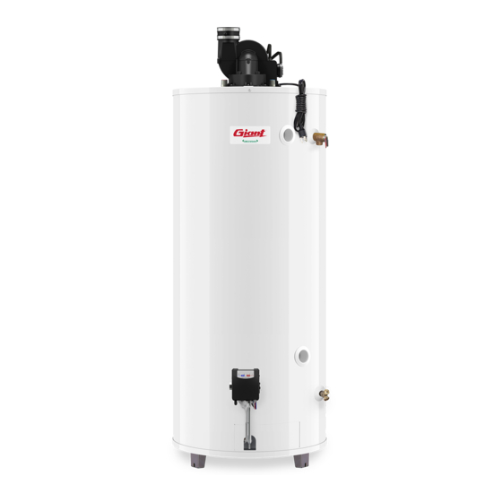
LIGHT DUTY COMMERCIAL POWER VENT GAS-FIRED WATER HEATERS
INSTALLATION AND OPERATING INSTRUCTIONS
READ THESE INSTRUCTIONS CAREFULLY BEFORE BEGINNING THE INSTALLATION. PROPER
INSTALLATION WILL PROVIDE SAFE AND EFFICIENT SERVICE, AND AVOID NEEDLESS EXPENSE NOT
COVERED BY THE WARRANTY. READ THE PRODUCT WARRANTY CONTAINED IN THIS MANUAL AND
REMEMBER TO FILL OUT AND RETURN TO THE MANUFACTURER ALL RELEVANT WARRANTY
CARDS AND CERTIFICATES. SHOULD YOU HAVE ANY QUESTIONS, PLEASE CONTACT YOUR LOCAL
DEALER OR REFER TO THE GETTING SERVICE FOR YOUR WATER HEATER SECTION OF THIS
MANUAL. SAVE THIS MANUAL FOR FUTURE REFERENCES.
For your records, write the model and serial number here:
Model # ________________________________
Serial # ________________________________
54000017
© 2012 Giant Factories Inc. Printed in Canada
OWNER'S MANUAL
This water heater IS NOT design certified for
installation in a manufactured (mobile) home or
for installation outdoors.
If the information in these instructions is not
followed exactly, a fire or explosion may
result causing property damage, personal
injury, or death.
DO NOT store or use gasoline or other
flammable vapours and liquids in the vicinity of
this or any other appliance.
WHAT TO DO IF YOU SMELL GAS
• DO NOT try to light any appliance.
• DO NOT touch any electrical switch,
DO NOT use any phone in your building.
• From a neighbour's phone, immediately
call your gas supplier. Follow the gas
supplier's instructions.
• If you cannot reach your gas supplier, call the
fire department.
Installation and service must be performed by
a qualified installer, service agency, or the gas
supplier.
IMPORTANT
WARNING
DANGER
AVERTISSEMENT
WARNING
DANGER
AVERTISSEMENT
ISO 9001
ENREGISTRÉ
ISO 9001
REGISTRED
GI-IM006En-0312
Advertisement
Table of Contents

Subscribe to Our Youtube Channel
Related Manuals for Giant LIGHT DUTY COMMERCIAL POWER VENT GAS-FIRED WATER HEATERS


Summary of Contents for Giant LIGHT DUTY COMMERCIAL POWER VENT GAS-FIRED WATER HEATERS
- Page 1 LIGHT DUTY COMMERCIAL POWER VENT GAS-FIRED WATER HEATERS OWNER’S MANUAL INSTALLATION AND OPERATING INSTRUCTIONS WARNING This water heater IS NOT design certified for DANGER installation in a manufactured (mobile) home or for installation outdoors. AVERTISSEMENT WARNING If the information in these instructions is not...
-
Page 2: Table Of Contents
TABLE OF CONTENTS Safety Information ......2 Wiring ....... . . 12 Installation Instructions . -
Page 3: Installation Instructions
INSTALLATION INSTRUCTIONS IMPORTANT These instructions have been written as a guide for the proper installation and operation of your water heater, and the manufacturer of this water heater will not accept any liability where these instructions have not been followed. However, for your safety and to avoid damage caused by improper installation, this water heater must be installed by a Certified Licensed Professional, and meet all local codes or, in the absence of local codes, CAN/ CSA B149.1, Natural Gas and Propane Gas Installation Code, in Canada, and/or the National Fuel Gas Code,... -
Page 4: Combustion And Ventilation Air Supply
INSTALLATION INSTRUCTIONS In Canada (refer to CAN/CSA B149.1) Figure 1 1) All Air From Inside the Building (see Figure 2): The confined space shall be provided with one opening of one (1) in /1,000 BTU (22.0 cm /kW) 18'' communicating directly with one or more min. -
Page 5: Louvers And Grilles
INSTALLATION INSTRUCTIONS B) When communicating with the outdoors through Each opening shall have a minimum free area of /kW) of the total vertical ducts, each opening shall have a minimum one (1) in /1,000 BTU (22.0 cm input rating of all gas appliances in the confined free area of one (1) in /kW) of /4,000 BTU (5.5 cm... -
Page 6: Corrosive Atmospheres
INSTALLATION INSTRUCTIONS than inch (6.4 mm) mesh. If the free area through ances from combustible material, all venting require- a particular design of louver or grille is known, it ments (see Table 1), and that the vent terminal will be should be used in calculating the size of opening installed as specified by all local codes or, in the required to provide the free area specified. - Page 7 INSTALLATION INSTRUCTIONS Figure 9 6 feet Min. Non mechanical air supply AREA WHERE TERMINAL IS NOT PERMITTED Mechanical air supply The Vent Termination must have a : Canadian Installations US Installations A) Clearance above grade, veranda, porch, deck, or balcony. 12 inches (30 cm) 12 inches (30 cm) B) Clearance to window or door that may be opened.
-
Page 8: Through-The-Wall Venting Installation
INSTALLATION INSTRUCTIONS 45˚ elbow. The pipe and all the fittings must be per- inches (45.7 cm) from the exterior surface of the roof manently joined using the appropriate primer and (see Figure 8). Make sure that all piping is properly solvent-based cement. - Page 9 INSTALLATION INSTRUCTIONS Figure 10 Minimum Slope 1/4”/foot (21 mm/m) 1) Vent pipe 16) Gas supply 2) Power vent assembly manual shut-off valve 3) Union 17) Union 4) Cold water 18) Gas control valve manual shut-off valve 19) Rating plate 5) Cold water inlet 20) Side tappings 6) Expansion tank 21) Dip Tube...
-
Page 10: Pressure Build-Up In A Water System
INSTALLATION INSTRUCTIONS Pressure Build-up in a Water System heater, consult CAN/CSA B149.1, National Gas and When the water heater operates, the heated water Propane Installation Codes (in Canada) and/or the expands creating a pressure build-up. This is a natural National Fuel Gas Code, ANSI Z223.1/NFPA 54, in the function and is one of the reasons for installing a United States. -
Page 11: Installation Instructions For Water Heaters
INSTALLATION INSTRUCTIONS pressure and expansion tanks. Installation Instructions for Water Heaters 4) Do not use toxic chemicals to clean the potable Approved for Combination Space Heating and water heating system. Potable Water Heating (See Figure 11) A water heater cannot be used for space heating 5) Where water temperature in excess of 140 application only. -
Page 12: Wiring
INSTALLATION INSTRUCTIONS Make sure that none of the wires are grounded, have Note: It is good practice to oversize the water heater, split, or are broken. Verify that all wiring connections to ensure that all of the potential hot water are properly secured, as there is a possibility that requirements are available. -
Page 13: Installation Checklist
INSTALLATION INSTRUCTIONS Installation Checklist Location • Is the water heater located within the venting requirements and close to the main use of hot water? ..• Is the water heater protected from freezing temperatures? ..............• Has a drain pan been installed and piped to a free-flowing drain? ............•... -
Page 14: Operating Instructions
OPERATING INSTRUCTIONS WARNING Lighting the Water Heater Before lighting or re-lighting your water DO NOT light this water heater if: DANGER heater, make sure that you have read • It is not full of water. and understood all of the instructions •... -
Page 15: Water Temperature Regulation
OPERATING INSTRUCTIONS no further buttons are pressed. After thirty (30) Water Temperature Regulation seconds, the control will go back to “Sleep” mode, WARNING and both buttons will again have to be pressed to see the water temperature setting. Release both of the temperature adjustment buttons. -
Page 16: Out Of Fuel
GENERAL MAINTENANCE Condensation When hot water is drawn from the tank in frequent short bursts, a condition known as “stacking” is cre- As moisture from the products of combustion comes ated. “Stacking” is the result of increased cycling of into contact with the cold surface of the inner tank, it the burner and can produce very hot water tempera- may condense. -
Page 17: Venting System Inspection
GENERAL MAINTENANCE WARNING Venting System Inspection The venting system must be thoroughly inspected once a year. Check the area where the water heater is Hydrogen gas can be produced in a hot water sys- located to make sure that there is enough clean com- DANGER tem that has not been used for a long period of bustion and ventilation air. -
Page 18: Getting Service For Your Water Heater
GENERAL MAINTENANCE Getting Service for your Water Heater If you are having problems with your water heater, follow these three easy steps: 1) Consult the Troubleshooting Guide contained in this manual (see Page 19). It lists the most common problems experienced with your gas- fired water heater. -
Page 19: Replacement Parts
REPLACEMENT PARTS ID No Description Gas control valve Electric connector Igniter assembly Complete burner assembly Outer access door Inner access door Drain valve Overflow tube Dip-tube Temperature & pressure-relief valve Flue baffle Complete blower assembly Vent adaptor High limit control Vacuum switch Plastic-lined di-electric galvanized nipple 2 Magnesium anodes... -
Page 20: Troubleshooting Guide
TROUBLESHOOTING GUIDE WARNING Disconnect the electrical power before servicing the water heater. Service should only be performed by a qualified service technician. Failure to follow these instructions can result in personal injury and/or death. DANGER CONDITION (code#) CAUSE REMEDY An open earth ground circuit 1) Check that the earth ground conductor is properly connected at the fuse box or break- to the ignition. - Page 21 TROUBLESHOOTING GUIDE CONDITION CAUSE REMEDY No gas. Check with gas utility company. The burner will not ignite. Dirt in gas line. Notify utility. Install drip leg in gas line. Main burner line clogged. Clean. Check for source of trouble and correct. Defective gas control valve.
- Page 22 TROUBLESHOOTING GUIDE CONDITION CAUSE REMEDY Leaking water. Poorly sealed, hot or cold water Tighten threaded connections. connections, gas control valve threads, relief valve,or drain valve. Leakage from plumbing system or Inspect plumbing system and other appliances. other appliances. Refer to Condensation. Condensation.
- Page 24 NOTES : __________________________________________________________________________________________________ ___________________________________________________________________________________________________________ ___________________________________________________________________________________________________________ ___________________________________________________________________________________________________________ ___________________________________________________________________________________________________________ ___________________________________________________________________________________________________________ ___________________________________________________________________________________________________________ ___________________________________________________________________________________________________________ ___________________________________________________________________________________________________________ ___________________________________________________________________________________________________________ ___________________________________________________________________________________________________________ ___________________________________________________________________________________________________________ ___________________________________________________________________________________________________________ ___________________________________________________________________________________________________________ ___________________________________________________________________________________________________________ ___________________________________________________________________________________________________________ ___________________________________________________________________________________________________________ ___________________________________________________________________________________________________________ ___________________________________________________________________________________________________________ ___________________________________________________________________________________________________________ ___________________________________________________________________________________________________________ ___________________________________________________________________________________________________________ ___________________________________________________________________________________________________________ ___________________________________________________________________________________________________________ ___________________________________________________________________________________________________________ ___________________________________________________________________________________________________________ ___________________________________________________________________________________________________________ ___________________________________________________________________________________________________________ ___________________________________________________________________________________________________________ ___________________________________________________________________________________________________________ ___________________________________________________________________________________________________________ ___________________________________________________________________________________________________________ ___________________________________________________________________________________________________________ ___________________________________________________________________________________________________________ ___________________________________________________________________________________________________________...
Need help?
Do you have a question about the LIGHT DUTY COMMERCIAL POWER VENT GAS-FIRED WATER HEATERS and is the answer not in the manual?
Questions and answers