Giant UG40 Installation And Operating Manual
Residential gas water heaters
Hide thumbs
Also See for UG40:
Table of Contents
Advertisement
RESIDENTIAL GAS WATER HEATERS
WARNING: If the information in these instruc-
tions is not followed exactly, a fire or explosion
may result causing property damage, personal
injury or death.
- Do not store or use gasoline or other flam-
mable vapours and liquids in the vicinity of
this or any other appliance.
- WHAT TO DO IF YOU SMELL GAS:
• Do not try to light any appliance.
• Do not touch any electrical switch; do not
use any phone in your building.
• Immediately call your gas supplier from a
neighbor's phone. Follow the gas sup-
plier's instructions.
• If you cannot reach your gas supplier, call
the fire department.
- Installation and service must be performed by
a qualified installer, service agency or the
gas supplier.
ALL TECHNICAL AND WARRANTY QUESTIONS: SHOULD BE DIRECTED TO THE LOCAL DEALER FROM WHOM THE WATER HEATER WAS
PURCHASED. IF YOU ARE UNSUCCESSFUL, PLEASE CONTACT THE COMPANY LISTED ON THE RATING PLATE ON THE WATER HEATER.
KEEP THIS MANUAL IN THE POCKET ON HEATER FOR FUTURE REFERENCE
04/2023
Canadian Installation and Operating Manual
WHENEVER MAINTENANCE ADJUSTMENT OR SERVICE IS REQUIRED.
POWER DIRECT VENT GAS MODELS
WITH HOT SURFACE IGNITION
NOT FOR USE IN MANUFACTURED (MOBILE) HOMES
VACATION
WARM
COOLER
Read and understand instruction
manual and safety messages
before installing, operating or
servicing this water heater.
Failure to follow instructions and
safety messages could result in
death or serious injury.
Instruction manual must remain
with water heater.
•
For Your Safety
AN ODOURANT IS ADDED TO THE GAS USED
BY THIS WATER HEATER.
A
B
C
VERY
HOT
HOTTER
WARNING
•
100363229_2000619026_01
Advertisement
Table of Contents

Subscribe to Our Youtube Channel
Related Manuals for Giant UG40


Summary of Contents for Giant UG40
- Page 1 Canadian Installation and Operating Manual RESIDENTIAL GAS WATER HEATERS POWER DIRECT VENT GAS MODELS WITH HOT SURFACE IGNITION NOT FOR USE IN MANUFACTURED (MOBILE) HOMES WARNING: If the information in these instruc- tions is not followed exactly, a fire or explosion VACATION may result causing property damage, personal VERY...
-
Page 2: Table Of Contents
TABLE OF CONTENTS Safe Installation, Use And Service ....3 Vent Terminal Installations General Safety ....... . 4 Blower Assembly Installation. -
Page 3: Safe Installation, Use And Service
SAFE INSTALLATION, USE AND SERVICE Your safety and the safety of others is extremely important in the installation, use and servicing of this water heater. Many safety-related messages and instructions have been provided in this manual and on your own water heater to warn you and others of a potential injury hazard. -
Page 4: General Safety
GENERAL SAFETY WARNING WARNING Read and understand instruction Fire Hazard manual and safety messages For continued protection against before installing, operating or risk of fire: servicing this water heater. • Do not install water heater on Failure to follow instructions and carpeted floor. - Page 5 GENERAL SAFETY CAUTION WARNING Improper Installation, use and service may result • Before servicing the water heater, make sure the blower assembly is unplugged in property damage. or the electrical supply to the water • Do not operate water heater if flood damaged. heater is tumed "OFF".
-
Page 6: Introduction
INTRODUCTION Thank You for purchasing this water heater. Properly and local code authority having jurisdiction. In installed and maintained, it should give you years of trouble absence of local codes, installation must comply with free service. current editions of the “Natural Gas and Propane Installation Code”... -
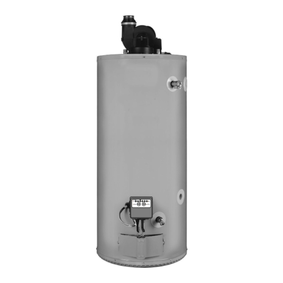
Page 7: Typical Installation
TYPICAL INSTALLATION GET TO KNOW YOUR WATER HEATER - GAS MODELS (LIST REFERENCING FIGURES 1-5) 1 Termination Elbow with Vent Screen 18 Flexible Manifold Tube (see 37 Gas Orifice (see Figure 3 & 2 *Vent Pipe Figure 3 & Figure Figure 3 *Vent Pipe Elbow (long radius) 19 ***Control Harness... -
Page 8: Replacement Parts And Deliming Products
Natural gas and Propane main Vacuum relief valve burner with igniter assembly install per local for 40k and 45k Btu/hr models codes (not supplied (item Figure 1) †. with heater). Figure 6. Notes: Items not supplied with the water heater. The side recirculation loop connections may not be used as the primary water inlet and outlet connections. -
Page 9: Water Piping - Mixing Valve Usage
WATER PIPING - MIXING VALVE USAGE In addition to using lowest possible temperature setting that satisfies demand of application, a mixing valve should Water temperature over 52°C DANGER be installed at hot-water taps to further reduce system (125°F) can cause severe water temperature. -
Page 10: Electrical Requirements & Wiring Diagram
ELECTRICAL REQUIREMENTS & WIRING DIAGRAM CAUTION: LABEL ALL WIRES PRIOR TO DISCONNECTION WHEN SERVICING CONTROLS. WIRING ERRORS CAN WARNING CAUSE IMPROPER AND DANGEROUS OPERATION. VERIFY PROPER OPERATION AFTER SERVICING. Electric Shock Hazard POWER VENT WIRING SCHEMATIC. Disconnect power before Elecrical Connections for White-Rodgers Valve servicing. -
Page 11: Safety Lockouts
SAFETY LOCKOUTS This water heater has several lockout features designed The switch will auto reset once the temperature drops to prevent the heater from operating in unsafe conditions. sufficiently. HIGH LIMIT CONTROLS (ENERGY CUT OFF) BLOWER AIR PRESSURE SWITCHES Thermostat/Water Temperature The blower/heater is equipped with two air pressure This feature is a part of the gas control valve/thermostat switches located in the junction box (see... -
Page 12: Clearances To Combustibles
Clearances For Servicing WARNING When installing the heater, consideration must be given to proper location. Location selected should be as close to Fire or Explosion Hazard the wall as practicable and as centralized with the water piping system as possible. •... -
Page 13: Important Notes And Warnings
AIR REQUIREMENTS WARNING For safe operation an adequate supply of fresh, uncontaminated air for combustion, dilution and ventilation Breathing Hazard - Carbon Monoxide Gas must be provided. Note: Contaminated or dusty air may cause build-up on • Flue gases may escape if the blower wheel resulting in nuisance shut downs. -
Page 14: Installing The New Water Heater
INSTALLING THE NEW WATER HEATER WATER PIPING Consult a Qualified Installer or Service Agency. Follow manufacturer’s instructions for installation of valves. Water temperature over 52°C DANGER Before changing the factory setting on thermostat, read (125°F) can cause severe “Operating The Temperature Control System” section in burns instantly resulting in severe injury or death. -
Page 15: Combo Heating
COMBO HEATING 2. Install a drain valve at the lowest point of the heating loop so that water can be drained from the heating This section serves as a guide for the installation and use module without affecting the water heater. of “Combo”... -
Page 16: Closed Water Systems
CLOSED WATER SYSTEMS SHUT-OFF VALVE COLD Water supply systems may, because of code requirements HOT WATER WATER OUTLET or such conditions as high line pressure, among others, INLET have installed devices such as pressure-reducing valves, UNION UNION check valves, and back flow preventers. Devices such as these cause the water system to be a closed system. -
Page 17: Temperature-Pressure Relief Valve
TEMPERATURE-PRESSURE RELIEF VALVE No valve or other obstruction is to be placed between the T&P valve and the tank. Do not connect discharge piping directly to the drain unless a maximum of 300mm WARNING (12 ”) air gap is provided. To prevent bodily injury, hazard to life, or property damage, the relief valve must be Explosion Hazard allowed to discharge water in adequate quantities should... -
Page 18: Temperature-Pressure Relief Valve And Pipe
Note: The purpose of a temperature-pressure relief valve HIGH ALTITUDE INSTALLATION is to prevent excessive temperatures and pressures in the storage tank. The T&P valve is not intended for the constant WARNING relief of thermal expansion. A properly sized thermal expansion tank must be installed on all closed systems to control thermal expansion, see “Closed Water Systems”... -
Page 19: Sediment Traps
Make sure the gas supplied is the same type listed on the excess of 1/2 psi. It should be isolated from the gas supply model rating plate. The inlet gas pressure must not exceed piping system by closing its individual manual shut-off 14”... -
Page 20: Filling The Water Heater
The sediment trap must be readily accessible. Install FILLING THE WATER HEATER in accordance with the “Gas Piping” section. Refer to the current edition of the “Natural Gas and Propane CAUTION Installation Code” B149.1 . Property Damage Hazard SHUT-OFF VALVE •... -
Page 21: Termination Clearances (Side Wall)
TERMINATION CLEARANCES (SIDE WALL) O R N D E C I N S I A I L D E T VENT TERMINAL AIR SUPPLY INLET AREA WHERE TERMINAL IS NOT PERMITTED F I X E S E D C L O R A B O P E F I X E... -
Page 22: Venting
VENTING CAUTION WARNING Improper Installation, use and service may result Breathing Hazard - Carbon Monoxide Gas in property damage. This unit includes an air intake terminal • Install water heater in accordance with the and an exhaust vent terminal. instruction manual and B149.1. •... -
Page 23: Side Wall Vent For Cold Climates
Side Wall Vent For Cold Climates should not interfere with it. Once the pilot hole is drilled, Some winter weather conditions present a risk of ice place the intake pipe in position and secure in place using accumulation at the intake termination screen. Such a #8 screw. -
Page 24: Tee Termination Installation
Tee Termination Installation 2 0 0 m “A” & “B”: ABOVE SNOW m ( 8 ” A Tee fitting as the exhaust termination and a 90° fitting ACCUMULATION LEVEL ) M I N OR 450mm (18”) MIN. as the air intake termination are permitted on the water ABOVE ROOF. -
Page 25: Concentric Vent Termination Installation
Concentric Vent Termination Installation 45° ELBOW A concentric vent termination kit (see Table 4) may be (SEE LOCAL CODES) used for vertical or horizontal terminations. Figure 26 PIPE NIPPLE illustrates the concentric vent kit for a horizontal (side wall) installation. To prevent rain water from entering the VENT SCREEN exhaust outlet, slope the vent kit at a downward pitch INSIDE... -
Page 26: Multiple Concentric Vent Installation
Multiple Concentric Vent Installation of cellular core PVC (ASTM F891), cellular core CPVC, When two concentric vent kits are being installed, the or Radel (polyphenolsulfone) in non-metallic venting ® vent hood centers shall be either less than 240mm (9.5”) systems is prohibited. apart or more than 1.1m (43.5”) apart. - Page 27 PRESSURE VENT WATER HEATER SWITCH 2 PIPE MAX. 2 PIPE CONC. VENT CONC. VENT SIZE HEATER INPUT SETTINGS (“ w.c.) EQUIV. VENT MIN. EQUIV. MAX. EQUIV. MIN. EQUIV. (Inside MODEL (Btu/hr) LENGTH VENT LENGTH VENT LENGTH VENT LENGTH Diam.) N.O. N.C.
-
Page 28: Vent Screens
Vent Screens For heater models 40-40 & 50-45 This water heater includes one (1) pair of more restrictive with 2” venting (short) with 2” venting (long) vent screens and one (1) pair of less restrictive vent screens (see Figure 32 &... -
Page 29: Vent Pipe Installation
This water heater has been design certified by CSA For heater models 50-58, 50-62, 75-72 & 75-76 International for use with the specified (CSA) listed plastic with 3” venting (short) with 3” venting (long) vent pipe. Do not use solvent cement to connect the exhaust vent system to the blower. -
Page 30: Blower Assembly Installation
BLOWER ASSEMBLY INSTALLATION Important: These connections must be properly seated and tightened to prevent the leakage of flue gases into the 1. This power vented water heater comes with blower area. See Figure 35 thru Figure assembly installed. 2. The 40 and 50-gallon heaters with rated inputs of 45k 2. - Page 31 2” INLET 2” VENT PIPE 3” INLET PIPE 3” VENT PIPE 2”-3” PIPE ADAPTER (SUPPLIED) 3” RUBBER 2” RUBBER COUPLING COUPLING (SUPPLIED) 3” PIPE (SUPPLIED) (SUPPLIED) BLOWER BLOWER AIR DUCT AIR DUCT ADAPTER ADAPTER CONFIGURATION FOR HI-INPUT HEATERS CONNECTED TO 3” CONFIGURATION FOR 40 AND 50 GALLON (LO-INPUT) HEATERS VENTING.
-
Page 32: Condensate
CONDENSATE SOUND SUPPRESSOR (OPTIONAL) In certain conditions, installations in unconditioned The sound suppressor can reduce the noise generated space or having long horizontal or vertical vent runs can by the water heater heard outside. Depending on the accumulate condensate. Long lengths of venting that pass configuration of the water heater, the sound suppressor through cool/cold areas will experience condensation. -
Page 33: Installation Checklist
INSTALLATION CHECKLIST Note: Use and complete this checklist before lighting the heater. Correct any conditions that do not meet these instructions. Vent Termination Water Heater Location Horizontal Centrally located with the water piping system. 300mm (12”) min. above grade/snow level. Located as close to gas piping and vent pipe system as possible. -
Page 34: Lighting Instructions
LIGHTING INSTRUCTIONS Read and understand these directions thoroughly before attempting to operate the water heater. Make sure the burner viewport is not missing or damaged. Make sure the tank is completely filled with water before operating the water heater. Check the label on the front of the water heater near the gas control/thermostat for the correct gas, Do not start this water heater with any gas other than the one listed on the label. -
Page 35: Operating The Temperature Control System
OPERATING THE TEMPERATURE CONTROL SYSTEM It is recommended that lower water temperatures be used The water heater should be located in an area where to avoid the risk of scalding. It is further recommended, the general public does not have access. If a suitable in all cases, that the water temperature be set for the area is not available, a cover should be installed over the lowest temperature which satisfies your hot-water needs. -
Page 36: Gas Control Valve/Thermostat
GAS CONTROL VALVE/THERMOSTAT APPROXIMATE DISPLAY TEMPERATURE °C (°F) 21°C (70°F) (VACATION) 43°C (110°F) 46°C (115°F) 49°C (120°F) 52°C (125°F) 54°C (130°F) 57°C (135°F) 60°C (140°F) 63°C (145°F)* Figure 42. 65°C (150°F)* The temperature of the water can be selected by using the temperature adjustment buttons on the front of the gas 71°C (160°F)* control (see Figure 42) as follows:... -
Page 37: For Your Information
FOR YOUR INFORMATION START UP CONDITIONS OPERATIONAL CONDITIONS Condensation Smelly Water Whenever the water heater is filled with cold water, some Each water heater contains at least one anode rod for condensate will form while the burner is ON. A water corrosion protection of the tank. -
Page 38: Periodic Maintenance
PERIODIC MAINTENANCE GENERAL UPKEEP Chemical vapour corrosion of the flue and vent system may occur if air for combustion contains certain chemical Make it a habit to look around the heater, the vent piping, vapours. Spray can propellants, cleaning solvents, and the hot and cold water pipes. -
Page 39: Combustion Chamber And Burner Cleaning
When checking the temperature-pressure relief valve operation, make sure that (1) no one is in front of or around BLUE TIPS the outlet of the T&P valve discharge line, and (2) that water discharge will not cause any property damage, as LIGHT BLUE INNER INCORRECT CONES ARE... -
Page 40: Draining And Flushing
10. Follow instructions in the “Filling The Water Heater” WARNING section. 11. Follow the lighting instructions on the label or see Explosion Hazard “Lighting Instructions” to restart the water heater. Note: If the water heater is going to remain shut down and •... -
Page 41: Anode Rod Maintenance
To Install a Combination Heat Trap Nipple/ ANODE ROD MAINTENANCE Anode (on some models) Note: Whether re-installing or replacing the anode rod, check for any leaks and immediately correct if found. Use Teflon® tape or an approved pipe sealant on threads of the new combination anode rod. -
Page 42: Leakage Checkpoints
LEAKAGE CHECKPOINTS SERVICE Leakage from other appliances, water lines, or ground seepage should also be checked. If a condition persists or you are uncertain about the operation of the water heater contact a service agency. * To check where threaded portion enters tank, insert Use this guide to check a “leaking”... -
Page 43: Reference Parts Listing
REFERENCE PARTS LISTING Replacement parts may be ordered 14 Outer Gas Door 39 Hot-Surface Igniter (see Figure 3 through your plumber or the local 15 Manifold Door Assembly (behind outer & Figure 4) (see also Figure 51 & distributor. When ordering replacement door) (see Figure 3 &... - Page 44 Natural gas and Propane Shown with (LP) main burner with Junction Box Cover igniter assembly for 40k removed for clarity. and 45k Btu/hr models (item Figure † Flare †† Figure 53. Figure 51. Notes: Items not supplied with the water heater. Natural gas and Propane The side recirculation loop connections may not be (LP) main burner with...
-
Page 45: Troubleshooting Guidelines
TROUBLESHOOTING GUIDELINES White-Rodgers These guidelines should be utilized by a qualified service agent. Ignition State Timing Pre-purge 5 seconds LOCKOUTS Igniter Warmup 10 seconds Soft Lockout • Trial For Ignition 4 seconds Occurs when a system safety device trips to break the sequence of operation. -
Page 46: System Status And Error Codes
Sytem Error Codes (White-Rodgers) The computer inside the gas control monitors the ignition sequence, temperature settings and overall operation of the heater. If any of these parameters does not operate properly the computer will shut down the water heater and flash an error code. See the “Intelli-Vent System Error Codes”... - Page 47 Symptom Possible Cause(s) Corrective Action Flame signal sensed out of proper 1. Ensure flame sensor ceramic insulator is not sequence. cracked. Error 10 2. Turn power off for 10-20 seconds, and then on again to clear the error code. 3. Replace the control. The high temperature thermal cutoff 1.
-
Page 48: Other Symptoms
OTHER SYMPTOMS Problem Possible Cause(S) Corrective Action 1. Thermostat set too low 1. Turn temperature knob to higher setting 2. Leaking faucets/Wasted hot water 2. Repair faucets 3. Wrong piping connections 3. Correct piping: dip tube must be in cold inlet Insufficient 4. -
Page 49: Notes
NOTES... - Page 50 NOTES...
Need help?
Do you have a question about the UG40 and is the answer not in the manual?
Questions and answers