Table of Contents
Advertisement
Quick Links
Advertisement
Table of Contents

Related Manuals for EM Acoustics HALO System


Summary of Contents for EM Acoustics HALO System
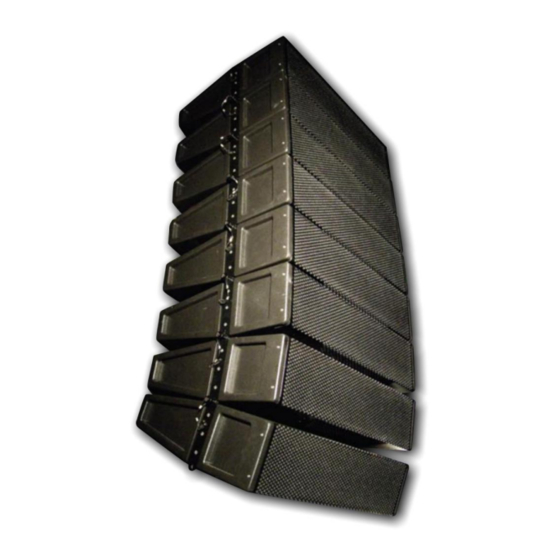
- Page 1 HALO System User Manual V2.2 August 2010...
-
Page 2: Table Of Contents
Page 2 of 39 Contents Declaration of Conformity Page 3 1.0 - Introduction Page 4 2.0 - The HALO System Page 5 3.0 - Connections, Processor & Amplifier Selection Page 6 4.0 - Flying HALO Systems Page 9 4.1 - Assembling Flown Arrays with subwoofers Page 12 4.2 - Assembling Flown Arrays without subwoofers... -
Page 3: Declaration Of Conformity
The packaging supplied with this product is recyclable. Please retain all packaging, however if disposing of this packaging please ensure that you comply with local recycling regulations. These products also all comply to the RoHS Directive 2002/95/EC. HALO system User Manual V2.2 August 2010... -
Page 4: Introduction
EM Acoustics representative. The HALO system is one of the only line array loudspeaker systems in the world to utilize genuine ribbon transducers for high frequency reproduction, resulting in incredible detail and clarity as well as superior feedback rejection. -
Page 5: The Halo System
HALO enclosure, plus a detachable base board for ground-stacking and storage. c) MFG-HALO master flying grid The MFG-HALO grid is the main grid for the HALO system which can be used for flying HALO enclosures on their own, but must be used to suspend HALO-S subwoofers. -
Page 6: Connections, Processor & Amplifier Selection
Amplifier Powers We recommend the following power inputs for HALO enclosures: HALO LF/MF (8 ohm impedance) 500W RMS, 1000W Program HALO HF 375W RMS, 750W Program HALO-S (4 ohm impedance) 1000W RMS, 2000W Program HALO system User Manual V2.2 August 2010... - Page 7 2500-3000 watts into a 2-ohm load. NOTE: A small amplifier working too hard is much more likely to damage your loudspeakers than a large amplifier working well within its limits! HALO system User Manual V2.2 August 2010...
- Page 8 Lake processing – either stand-alone units or incorporated into the LabGruppen PLM series of amplifier products. The DSP program detailed below is based around a 12-HALO system flown with a single HALO-S subwoofer at the top of the array. Crossover points between HALO/HALO-S are of course at the user‟s discretion, as are gain structures.
-
Page 9: Flying Halo Systems
EM Acoustics will not be responsible for any loss, damage or injury caused by such practice. Welding, drilling or any other means of modifying any part of the flying hardware or permanently fixing components to each other is strictly forbidden. - Page 10 EM Acoustics recommends detailed logbooks be kept of all inspections and load tests to ensure an accurate record is kept of the testing for each EM Acoustics rigging accessory. When flying any loudspeaker system, always wear protective headwear, footwear and eye protection in accordance with local regulations.
- Page 11 Page 11 of 39 Safety Factors The HALO system is designed to work within the following safety factors: MFG-HALO – Safety factor of 4 22 x HALO enclosure 20 x HALO enclosure 1 x SLG-HALO grid 1 x HALO-S enclosure...
-
Page 12: Assembling Flown Arrays With Subwoofers
Page 12 of 39 4.1 - Assembling Flown Arrays with Subwoofers HALO system User Manual V2.2 August 2010... - Page 13 Firstly, ensure you have the correct front drop links in place to fly your chosen system. In this example, we are flying a HALO-S subwoofer at the top of the array and as such we want the larger of the two links as shown in the image below. HALO system User Manual V2.2 August 2010...
- Page 14 Once you have established the appropriate front drop-links, move the links into the usage position by removing the lower ball-lock pin which will allow the link to swing freely, and then replace the ball-lock pin to lock the link in position. HALO system User Manual V2.2 August 2010...
- Page 15 The first, and most common is by using the movable pick-up links which allow for both single point and dual point pick-up. These links are stored for transit on the side of the MFG grid and are secured in place by two 3/8” ball-lock pins. HALO system User Manual V2.2 August 2010...
- Page 16 The second means of securing pick-up points on the MFG-HALO grid is to use the four holes located front & rear on the grid to attach 3.25 ton bow shackles, and bridle between HALO system User Manual V2.2 August 2010...
- Page 17 MFG-HALO grid locate within the rigging hardware on the cabinet. Once the grid is in position, secure the grid to the enclosure using the four ball-lock pins on the HALO-S enclosure. HALO system User Manual V2.2 August 2010...
- Page 18 The SLG-HALO grid provides the mechanical link between the HALO-S and the much shallower HALO enclosure. It is specifically designed to give the same flexibility to the HALO array is if you were flying straight from a MFG-HALO grid. HALO system User Manual V2.2 August 2010...
- Page 19 Release this pin and rotate the link to the desired position – either 0 degrees (top HALO enclosure is parallel to the grid) or 5 degrees (top enclosure is angled down 5 degrees relative to the SLG grid). Secure in position with the ball-lock pin as shown below. HALO system User Manual V2.2 August 2010...
- Page 20 As shown below, position your HALO enclosures beneath the array. Release the ball-lock pins on both sides of the front rigging, and also the lock position on the rear splay rigging. HALO system User Manual V2.2 August 2010...
- Page 21 Additionally, when sliding the link out of its housing, the first full number shown is the angle at which the link is set at – see photos below. HALO system User Manual V2.2 August 2010...
-
Page 22: Assembling Flown Arrays Without Subwoofers
Page 22 of 39 4.2 - Assembling Flown Arrays without Subwoofers The procedure to assemble the HALO system without subwoofers is largely identical to that described above. Step One – MFG-HALO grid preparation The drop links for the MFG-HALO grid are stored inside the chassis of the flying grid for transport. - Page 23 Once you have established the appropriate front drop-links, move the links into the usage position by removing the lower ball-lock pin which will allow the link to swing freely, and then replace the ball-lock pin to lock the link in position. HALO system User Manual V2.2 August 2010...
- Page 24 Repeat this process for the second pick-up link. IMPORTANT NOTE: Both 3/8” ball-lock pins MUST be secured on each pick-up link being used. HALO system User Manual V2.2 August 2010...
- Page 25 (top HALO enclosure is parallel to the grid) or 5 degrees (top enclosure is angled down 5 degrees relative to the SLG grid). Secure in position with the ball-lock pin as shown below. HALO system User Manual V2.2 August 2010...
- Page 26 As shown below, position your HALO enclosures beneath the array. Release the ball-lock pins on both sides of the front rigging, and also the lock position on the rear splay rigging. HALO system User Manual V2.2 August 2010...
- Page 27 Additionally, when sliding the link out of its housing, the first full number shown is the angle at which the link is set at – see photos below. HALO system User Manual V2.2 August 2010...
-
Page 28: Assembling Flown Arrays With The Fg-Halo Grid
„break‟ the array. It is appreciated that whilst it is not acoustically ideal to break the array in some ways (slight loss of coupling for example) we at EM acoustics believe the benefits of being able to approach otherwise challenging venues makes the addition of this feature worthwhile. -
Page 29: Ground Stacked Systems
& without subwoofers. Method A – With HALO-S subwoofers The best way to imagine a ground-stacked HALO system is simply a flown system upside down. So, the first step is to move the base board from the HALO-S enclosure due to go on the bottom of the stack. -
Page 30: Servicing Information
& blue cables for the HF drive unit and remove these cables. Carefully remove the silicone sealing compound around the hole for the HF drive unit cables. HALO system User Manual V2.2 August 2010... - Page 31 3. Using an Allen key, remove the six bolts securing the drive unit. Carefully lift the drive unit out of its mounting hole, being careful to avoid damaging the drive unit above. Disconnect the cables (noting polarity) and remove the drive unit fully. HALO system User Manual V2.2 August 2010...
- Page 32 Ensure the bolt holes line up. It is advisable to ensure each bolt has started in its thread before tightening any. Once the position is correct, tighten all six bolts but be careful not to overtighten. HALO system User Manual V2.2 August 2010...
-
Page 33: Appendix A - Technical Specifications
Grille Power-coated hex-punched steel. Aluminium hex-punched side grilles. All backed by acoustically-transparent fabric. Connectors: 2 x Neutrik Speakon STX NL4 Net/Shipping Weight: 26kg/29kg (57.2lbs/63.8lbs) Dimensions (HxWxD, mm/ins) : 172/6.8 x 747/29.4 x 488/19.2 HALO system User Manual V2.2 August 2010... - Page 34 65/68kg (143lbs/149.6lbs) Dimensions (HxWxD, mm/ins): 521/20.5 x 747/29.4 x 725/28.5 Notes on measurement conditions: Measured on-axis Average SPL over stated bandwidth with 1W input, measured at 1m Nominal dispersion, averaged over stated bandwidth HALO system User Manual V2.2 August 2010...
-
Page 35: Appendix B - Technical Drawings
Page 35 of 39 Appendix B – Technical Drawings HALO 3-way compact line array enclosure HALO system User Manual V2.2 August 2010... - Page 36 Page 36 of 39 HALO-S dual 15” flyable subwoofer HALO system User Manual V2.2 August 2010...
-
Page 37: Appendix C - Spare Parts
8 ohm recone kit for DU-601 01C014 RK-602 16 ohm recone kit for DU-602 (factory service only) 01D007 RD-AMT Replacement AMT diaphragm 05A019 HALO_PIN ¼” x ½” ball-lock flying pin with 4” lanyard HALO system User Manual V2.2 August 2010... -
Page 38: Appendix D - Warranty Information
EM Acoustics or its representatives are in no way liable for any loss or damage in transit, and hence it is recommended that the sender insure the shipment. EM Acoustics will pay for return freight should the repair be covered under warranty. -
Page 39: Halo System User Manual V2.2 August
Page 39 of 39 EM Acoustics‟ liability is to the replacement or repair (at our discretion) of any defective components, and as such are not liable for any incidental and consequential damages including (without limitation) injury to persons, damage to property or loss of use.
Need help?
Do you have a question about the HALO System and is the answer not in the manual?
Questions and answers