Table of Contents
Advertisement
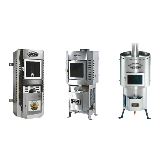
Natural Draft Diesel Heater
Operating and Installation
Instruction Manual
*KEEP THIS MANUAL FOR FUTURE REFERENCE*
Lofoten, Newport, Alaska, Antarctic Models
** Please read from beginning to end before installing and operating.
Heater's Serial #: __________________
Quality Controlled by- Doug & Don
Form#7.2-229 Issue#1 Jul 15, 2011
Advertisement
Table of Contents

Related Manuals for Dickinson Lofoten


Summary of Contents for Dickinson Lofoten
- Page 1 Natural Draft Diesel Heater Operating and Installation Instruction Manual *KEEP THIS MANUAL FOR FUTURE REFERENCE* Lofoten, Newport, Alaska, Antarctic Models ** Please read from beginning to end before installing and operating. Heater’s Serial #: __________________ Quality Controlled by- Doug & Don...
-
Page 2: Table Of Contents
Table of Contents Table of Contents… Pg. 2 Warnings… Pg. 3 1. About a Natural Draft Diesel Heater… Pg. 4 2. Important Notes... Pg. 4 3. Ventilation… Pg. 5 4. How does the Chimney affect the Heater… Pg. 6 - Testing your Draft… Pg. 7 - Downdraft…... -
Page 3: Warnings
11. Approximate Valve & Fan Settings… Pg. 22 - Fire Diagram… Pg. 22 12. Operation Tips… Pg. 23 - Importance of the “Fuel to Air” Mixture… Pg. 24 13. Flooding the Burner… Pg. 25 - Valve Height Requirements Diagram… Pg. 25 14. -
Page 4: About A Natural Draft Diesel Heater
3. Fuel- Input in proportion to the supply of draft and oxygen. Dickinson diesel heaters can also be calibrated to run kerosene (K) and stove oil (S). See “Fuel Variations” on Pg. 27. This code will be indicated on the side of the valve. -
Page 5: Ventilation
• Fuel must be filtered and not exceed a pressure of 4 psi or a fuel pressure regulator must be used to avoid dangerous flooding (Dickinson part# 20-003). • A barometric damper must be installed to help regulate the draft. A barometric gives you more control in the “fuel to air”... -
Page 6: How Does The Chimney Affect The Heater
A CO alarm should be installed in the boat. We also recommend the Dickinson high heat shut-off #02-210. 4. How Does the Chimney affect the Heater? The heater does not create the draft for a natural draft appliance to operate; it is the chimney that creates the draft for operation. -
Page 7: Testing Your Draft
3. Competition for available air. Third, there must not be too much competition from other devices in the boat, such as exhaust fans, a large engine or air-exchange systems. If something else is sucking the air out of the boat, the chimney might not be powerful enough to overcome it, and exhaust might be drawn into the boat from the chimney. -
Page 8: Safety Clearances
ceramic tile. The wall behind the heater and the first length of chimney pipe should also be lined with such material. See diagram below. Safety Clearances Above- 30”, In front- 18”, Sides- 12”, Below- 6” Facing Direction The heater ideally should face the bow or stern of the boat, particularly on a sailboat. -
Page 9: Mounting
Chimney Pipe Diameters Newport, Alaska & Antarctic Heaters- 3” diameter chimney (7.5cm) Lofoten- 4” diameter chimney (10cm) Barometric Damper We have 2 options for installing the barometric damper into your chimney. - Page 10 Lofoten model heater Part# 17-001: 4” x 22” stainless pipe with barometric Part# 17-010: 4” x 7” stainless pipe with barometric The barometric damper should be installed in oil and solid fuel heaters. The purpose is to maintain a strong draft without causing too much air to the “fuel to air”...
-
Page 11: Deck Fitting
A hole through the center of the block would also be 2 inches greater then the diameter of the flue pipe. *The Lofoten model has a 4” diameter pipe so it would need a 6” hole. Exhaust Cap The Dickinson DP or H style exhaust caps are most recommended. -
Page 12: Heater Installation Diagram
Heater Installation Diagram... -
Page 13: Fuel System Installation
6. Fuel System Installation For efficient and safe operation of the heater, follow all recommendations for properly installing the fuel system. DANGER: Never use gasoline in a heater. Use only #2 diesel, #1 stove oil or kerosene. The valves are factory calibrated to #2 diesel; if #1stove oil or kerosene is preferred, the valves can be re-calibrated to suit those viscosities. -
Page 14: Fuel Filter & Manual Shut-Off's
out of the valve. For this reason a manual shut-off will need to be teed in the overflow line and closed when refilling tanks. CAUTION: After refilling, you will need to burn off the fuel in the line before re-opening the shut-off valve. -
Page 15: Walbro Pump Installation
7. Walbro Fuel Pump Installation When installing a Walbro fuel pump you must ensure it is mounted approximately at the level of the valve on the heater. These pumps can “pull” fuel but have trouble “pushing” fuel so it must be gravity fed from the pump to the heater. -
Page 16: Walbro Frd-2 Pump Upgrade
& regulator. info@dickinsonmarine.com Once you have received a stronger spring and regulator from Dickinson, you can upgrade your pump to a stronger pressure. Unscrew the 3 torx screws (t- 20) and with twisting the lid back and forth, pull it straight back off. Note the pump plunger, spring, check valve, and a very small amount of fuel will drop out if installed as per diagram. -
Page 17: Exploded Fuel Pump Diagram
spring. Replace the lid with the gasket on by lowering your finger on to the red O ring sleeve without the plunger falling out (the plunger is about 2” long so you have room to lower your finger out of the way). The red O ring sleeve will fit inside the pump tube and the black O ring will fit over the outside of the pump tube and will require twisting and pushing the lid straight back in. -
Page 18: Draft Assist Fan Installation
8. Draft Assist Fan Installation The 12v draft assist is not needed for operation but highly recommended as it will help to vaporize the fuel and give more control in burning the heater as clean as possible. The fan is a 12v DC fan that the draw is .17amp. The fan is 12v and if 24v or 32v is needed, resistors are available. -
Page 19: Water Coil Installation
5-10 gallons of water. Hot water coils are also available in 2 turn coils for only the Antarctic and Lofoten models to heat approx. 15-20 gallons of water. To plumb the hot water to the heater, ½”... -
Page 20: Water Coil Diagrams
3. Punch out the 2 knockouts on the back of the heater or drill them if not there. 4. Fit the coil inside the firebox and through the 2 holes in the back panel leaving about 2” sticking out the back. 6. -
Page 21: Heater Operation
10. Operation The first time the oil-metering valve is turned on it will take 5-10 minutes for the fuel lines to fill and oil to appear in the bottom of the burner. Lighting Procedure 1. Turn on the fuel pump or open the gravity feed valve to allow fuel to flow into the oil metering valve on the heater. -
Page 22: Approximate Valve & Fan Settings
11. Approximate Valve & Fan Settings Heater Temperature Valve Setting Fan Knob Position Cold Start # 2 to # 3 Warm Low # 1 to # 2 Warm Low (cold or windy) # 2 to # 3 4 to 5 o’clock Medium # 3 to # 4 5 to 6 o’clock... -
Page 23: Operation Tips
An adjustment will have to be made to turn down the fuel to a lower setting or add more air for a higher setting. Please visit our website and view Dickinson Marine’s Operation Video www.dickinsonmarine.com/video.html... -
Page 25: Flooding The Burner
13. Flooding the Burner A vaporizing oil burner of this type can be flooded if care is not taken to prevent excess oil entering the burner when lighting. By following the lighting instructions flooding will be avoided. A flooded burner that is still burning should be turned off and the heater monitored until the oil has burned off. -
Page 26: The Oil Metering Valve & Fuel Flow
14. The Oil Metering Valve & Fuel Flow Safety Fuse A high temperature fuse is incorporated into the oil metering valve. The adjusting screw on the top of the knob of the oil metering valve is fitted with a fusible sleeve. This fuse will melt if the valve knob reaches a temperature of 165 degrees F. -
Page 27: Fuel Flow Measurements
Fuel Flow Measurements If your heater is burning rich (making soot or smoking) or burning lean (flames not burning above the top burner ring), adjust the valve fuel flow as follows regardless of what type of fuel: Unscrew the compression nut from the bottom of the valve with 2 wrenches and bend away the copper fuel line. -
Page 28: Valve Operating Ranges
Oil Metering Valve Operating Ranges Oil Metering Valve Repair Kits The oil metering valves have 3 generations as the size of the inside components have changed over the years. Valves from the 2006 to present generation will have a “C” stamped on the side of the valve. Before 1994: No components available (must replace valve) 1994-2006: Repair Kit part# 02-200 2006- Present: Repair Kit part# 02-200C... -
Page 29: Valve Repair
Oil Metering Valve Repair The repair kit has been packed with all the parts to rebuild your oil metering valve. The parts may differ in detail from what you have in your valve. This is due to changes and to the unavailability to the parts over the decades. 1. - Page 30 down, the bottom of the float should be parallel to the casting of the valve, in both directions). This very important to keep the float from binding on the stem guide as it moves up and down. If the float is not parallel to the casting, the float pin tabs on the float will need adjusting.
-
Page 31: Exploded Valve Diagram
Oil Metering Valve Diagram... -
Page 32: Burner Assembly
15. Burner Assembly Your diesel heater has been equipped with a 6” “Airflow” burner. There are two components in the burner that must be correctly placed for the heater to operate properly. The burner ring must be placed at the top of the pot so the outside edge of the ring fits into the groove in the top of the pot. -
Page 33: Maintenance
16. Maintenance Fuel Maintenance Checklist (CHECK ONCE A YEAR) 1) Disconnect the fuel inlet line from the valve and place into a bucket. Turn on your pump or open your gravity feed valve to ensure there is a constant flow of fuel. This will indicate your fuel filter and fuel pump are operating correctly. -
Page 34: Cleaning The Fuel Lines
Replacement Parts *Replacement Valve: Newport & Alaska- part# 02-011, Antarctic- part# 02- 000, Lofoten- part# 02-019 *Replacement Fan: Newport & Alaska- part# 01-031, Antarctic & Lofoten- part# 01-030 *Replacement 12v Fan Speed Control: Newport, Alaska, Antarctic & Lofoten: part# 01-072 *Replacement 6”... -
Page 35: Trouble Shooting
17. Trouble Shooting *Flames are burning incorrectly inside the burner pot- The flames are burning too lean, this is to say too much air and/or not enough fuel. Reduce the air intake first by adjusting the barometric damper flap open to 3/8”. This will keep the draft in the chimney strong but reduce the amount of air being drawn into the burner. - Page 36 The chimney may not be getting hot enough to create a strong draft Pg 5-7. Turn the fan on to a very slow speed but balance the fuel to keep flames above the ring Pg 18. Adjust the barometric flap so it is open between ¼ to 3/8 Pg 9.
-
Page 37: Warranty Policy
18. Warranty Policy We at Dickinson wish to maintain a reasonable and easy system for returns, warranty, returns and exchanges. To accomplish this, we would like to inform you of some helpful guidelines and procedures to use and follow when sending back product to the Dickinson Marine. All correspondence... - Page 38 Dickinson offers to replace said parts free of charge, provided, however, that such parts have not been improperly repaired, altered or tampered with or subjected to misuse, abuse or exposed to corrosive conditions.
- Page 39 Give name, address, and model name, location of unit, description of problem and where you can be reached during business hours. RESERVED RIGHT TO CHANGE: Dickinson reserves the right to make changes or improvements to products it produces in the future without imposing on itself any obligations to install the same improvements in the products it has previously manufactured.
- Page 40 19. Register your Warranty….. Please register your warranty with Dickinson Marine. Fill out and send back the warranty registration below. Make sure to include the serial # for our records. No warranty will be extended for improper installations. Use of any unapproved materials, equipment, or installation procedures will result in a voided warranty.
- Page 41 All rights reserved. No part of this manual may be reproduced without permission in writing from Dickinson Marine. Dickinson also reserves the right to modify or change without notice, any materials, applications, equipment, accessories, and/or prices. All measurements and weights are approximate.
Need help?
Do you have a question about the Lofoten and is the answer not in the manual?
Questions and answers