Dickinson NEWPORT Operating Instructions Manual
Diesel heater
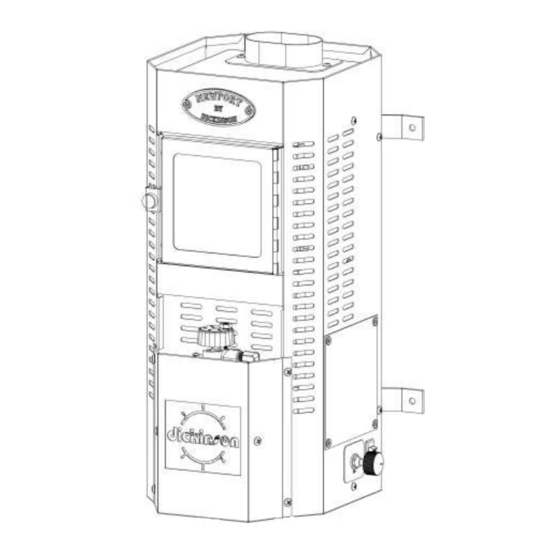
Hide thumbs
Also See for NEWPORT:
- Installation & operating instructions manual (53 pages) ,
- Operating and installation instruction manual (16 pages) ,
- Installation and operating manual (10 pages)
Table of Contents
Advertisement
Advertisement
Table of Contents

Related Manuals for Dickinson NEWPORT


Summary of Contents for Dickinson NEWPORT
- Page 1 INSTALLATION AND OPERATING MANUAL This manual MUST be read carefully and all requirements carried out to ensure satisfactory performance dickinson since 1932 Dickinson Marine (1997) Ltd 407-204 Cayer Street, Coquitlam, B.C. Canada V3K 5B1 www.dickinsonmarine.com E mail dmarine@dickinsonmarine.com...
-
Page 2: Warnings And Disclosures
WARNINGS AND DISCLOSURES FOLLOW ALL INSTALLATION AND OPERATING PROCEDURES A PERMANENTLY OPEN FRESH AIR INLET MUST BE INSTALLED TO ALLOW AIR TO ENTER THE BOAT AND PROVIDE COMBUSTION AIR FOR THE STOVE THE DIESEL FUEL SUPPLY MUST BE FILTERED (The element or filter MUST be changed every year) A BAROMETRIC FLUE DAMPER MUST BE INSTALLED IN FLUE STACKS LONGER THAN 6 FEET... - Page 3 3" diameter DP Flue Cap TYPICAL INSTALLATION NEWPORT HEATER 3" Thru-Deck Fitting Dress Ring 4 ft minimum Max 45 degrees 3" diameter Pipe Pressure Relief Valve Water Outlet Barometric Draft Damper 12"-24" Water 3/8" Vent Tank Gravity Fuel Tank Cold...
- Page 4 RECOMMENDED INSTALLATION REQUIREMENTS – NEWPORT HEATER 45 degree max Elbows 1/2" Spacers 3” Barometric Damper 12” High Heat Insulation Stainless Wall Liner Permanently open fresh air inlet Drip Tray 3/8”Copper Fuel Line Overflow...
-
Page 5: Installation
INSTALLATION LOCATION The space for the location of your Newport heater must be large enough to provide the required clearances (see installation diagrams - Pages 2 and 3). It must be lined with high density, heat retardant insulation and finished with a light gauge metal, preferably stainless steel. Particular care must be taken to protect the surfaces close to the edge of the top cooking surface and the chimney stack. - Page 6 FLUE CAP The Dickinson DP or H style flue caps are recommended. The location of the flue cap above deck must be clear of any immediate obstruction that may cause unusual air movement or turbulence. CAUTION : The Flue Cap gets hot when the stove is operating.
- Page 7 Thermal Mechanical Safety Shut-Off 5/64ths allen wrench securing screw OIL METERING VALVE 5/64ths allen wrench fuel flow adjusting Metering Stem screw. Adjust from top of knob. Spring Circlip 1/8" Mesh Screen on fuel "O"Ring Metering Slot Fuel Inlet Needle and Seat 3/8"Flare Float Float Hinge and...
- Page 8 FUEL - CONSUMPTION The Oil Metering Valve flow rate has been set at the time of manufacture. _____________________________________________________________________________________ cc/minute cc/hour litres/24 hours gallons/ 24 hours Low Fire 5.86 1.29 High Fire 14.54 3.20 _____________________________________________________________________________________ FUEL - VARIATIONS It is unlikely that the fuel you are using is the same viscosity as the fuel used to calibrate the oil-metering valve. Fuel viscosity differs on a routine basis even though you purchase the same grade of oil from the same supplier.
-
Page 9: High Temperature
THIS IS CAUSED BY INCORRECT OPERATING PROCEDURES. THE FLAME MUST BURN ABOVE THE BURNER RING AT ALL TIMES. If this occurs a replacement part is available from Dickinson. DO NOT LEAVE YOUR HEATER BURNING UNATTENDED... -
Page 10: Combustion Air
COMBUSTION AIR To guarantee that sufficient oxygen (fresh air) is available for your stove, GOOD VENTILATION IS ESSENTIAL. It is necessary to replace the air inside your boat at the same rate that the stove is removing it. THE HOTTER THE HEATER THE MORE AIR IT WILL REQUIRE. As most boats are relatively air tight a SEPARATE, PERMANENTLY OPEN, FRESH AIR INLET IS RECOMMENDED. - Page 11 WATER HEATING (OPTIONAL) The heater can be equipped with a single hot water heating coil. This optional item should be installed at time of manufacture but can be retrofitted later. Specifications Coil 5/8th ins O.D. stainless steel tubing Single Turn heats 6-10 gallon tank TYPICAL WATER HEATING INSTALLATION Pressure Relief Valve...
-
Page 12: Operation
Sediment in the valve needle and seat. ii) Valve float not free. iii) Excess pump pressure (more than 4 psi.) Tapping the side of the valve may correct the problem. ASSEMBLE THE BURNER AS DIAGRAM 6" dickinson AIRFLOWBURNER Stove Top Combustion Chamber Secondary Superheater... -
Page 13: Lighting Procedure
LIGHTING PROCEDURE See Page 1 of manual The first time the oil-metering valve is turned on it will take 5-10 minutes for the fuel lines to fill and oil to appear in the bottom of the burner. The burning characteristic of the flame during lighting is as follows :- Lighting (Primed) Preheating Fuel Vaporizing... - Page 14 A vaporizing oil burner of this type can be flooded if care is not taken to prevent excess oil entering the burner. By following the lighting instructions flooding will be avoided. Causes of burner FLOODING : Fuel entering the burner faster than it is burning. Increasing the fuel supply too quickly without use of the combustion assist fan.
-
Page 15: Combustion Chamber
Replace the float - Replace the float pin - Replace the top and tighten the screws DO NOT LIGHT THE STOVE UNTIL FLOW RATE HAS BEEN CHECKED (See Page 8) BURNER Carbon accumulates in the burner over a period of time and it must be cleaned routinely. If you are burning good quality fuel and the stove is burning efficiently this cleaning procedure will only be required once a year. -
Page 16: Troubleshooting
TROUBLE-SHOOTING NO FUEL OR INSUFFICIENT FUEL TO THE BURNER Cause Remedy Fuel filter plugged Clean Fuel line blocked Establish how far fuel has reached. Start at the burner and work back to the fuel tank. Air Lock in fuel line Check all fuel line fittings. - Page 17 Cause Remedy Not Enough Air or Draft Negative inside pressure Check fresh air inlets Negative inside pressure Provide adequate engine air supply when engine is running Flue stack elbows greater Revise flue stack configuration than 45 degrees Too Much Draft Long stack Reduce stack length or install barometric damper Running combustion assist...
- Page 18 If any part of your new product fails because of a manufacturing defect within the warranty period dickinson offers to replace said parts free of charge, provided, however, that such parts have not been improperly repaired, altered or tampered with or subjected to misuse, abuse or exposed to corrosive conditions.
Need help?
Do you have a question about the NEWPORT and is the answer not in the manual?
Questions and answers