Table of Contents
Advertisement
Quick Links
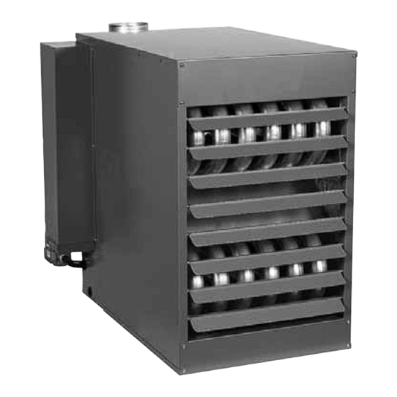
TUBULAR GAS FIRED DIRECT SPARK PROPELLER UNIT HEATERS
ATTENTION: READ THIS MANUAL AND ALL LABELS ATTACHED TO THE UNIT CAREFULLY BEFORE
ATTEMPTING TO INSTALL, OPERATE OR SERVICE THESE UNITS! CHECK UNIT DATA PLATE FOR TYPE OF GAS
AND ELECTRICAL SPECIFICATIONS AND MAKE CERTAIN THAT THESE AGREE WITH THOSE AT THE POINT OF
INSTALLATION. RECORD THE UNIT MODEL AND SERIAL No.(s) IN THE SPACE PROVIDED. RETAIN FOR FUTURE
REFERENCE.
Unit No.
The use and storage of gasoline or other fl ammable vapors and liquids in open containers in
the vicinity of this appliance is hazardous.
can cause property damage, injury, or death. Read the installation, operating, and
maintenance instruction thoroughly before installing or servicing this equipment.
instructions to avoid exposure to fuel substances, or substances from incomplete
combustion, which can cause death or serious illness. The state of California
has determined that these substances may cause cancer, birth defects, or other
reproductive harm.
Installer Please Note: This equipment has been test fired and inspected. It has been
shipped free from defects from our factory. However, shipment and installation
problems such as loose wires, leaks, or loose fasteners may occur. It is the installer's
responsibility to inspect and correct any problem that may be found.
RECEIVING INSTRUCTIONS
Inspect shipment immediately when
received to determine if any damage
has occurred to the unit during
shipment. After the unit has been
uncrated, check for any visible
damage to the unit. If any damage
is found, the consignee should sign
the bill of lading indicating such
damage and immediately file claim
for damage with the transportation
company.
07/13
INSTALLATION INSTRUCTIONS AND PARTS IDENTIFICATION
If you smell gas:
1. Open windows.
2. Don't touch electrical switches.
3. Extinguish any open fl ame.
4. Immediately contact your gas supplier.
Improper installation, adjustment, alteration, service, or maintenance
APPROVED FOR USE IN CALIFORNIA
APPROVED FOR USE IN CALIFORNIA
Install, operate, and maintain unit in accordance with the manufacturer's
INSTALLER'S RESPONSIBILITY
Serial No.
FOR YOUR SAFETY
FOR YOUR SAFETY
260 NORTH ELM ST., WESTFIELD, MA 01085
TEL: (413) 568-9571
DSTBIM-11
J30-06939
ENERGY
PERFORMANCE
CM
VERIFIED
RENDEMENT
ENERGETIQUE
VERIFIE
FAX: (413) 562-8437
www.mestek.com
Advertisement
Table of Contents

Related Manuals for Mestek TUBULAR GAS FIRED DIRECT SPARK PROPELLER UNIT HEATERS


Summary of Contents for Mestek TUBULAR GAS FIRED DIRECT SPARK PROPELLER UNIT HEATERS
- Page 1 J30-06939 INSTALLATION INSTRUCTIONS AND PARTS IDENTIFICATION TUBULAR GAS FIRED DIRECT SPARK PROPELLER UNIT HEATERS ATTENTION: READ THIS MANUAL AND ALL LABELS ATTACHED TO THE UNIT CAREFULLY BEFORE ATTEMPTING TO INSTALL, OPERATE OR SERVICE THESE UNITS! CHECK UNIT DATA PLATE FOR TYPE OF GAS AND ELECTRICAL SPECIFICATIONS AND MAKE CERTAIN THAT THESE AGREE WITH THOSE AT THE POINT OF INSTALLATION.
-
Page 2: Table Of Contents
TABLE OF CONTENTS SPECIFICATIONS ELECTRICAL CONNECTIONS ..... 10, 11, 12 Basic Description ............ 2 VENTING ........... 13, 14, 15, 16, 17 Performance & Specifi cation Data ......4 OPERATION GENERAL SAFETY INFORMATION Explanation of Controls and Operation ....18 Installation Codes ..........2, 3 Main Burner Orifi... -
Page 3: General Safety Information
GENERAL SAFETY INFORMATION Failure to comply with the general Do not attempt to convert the safety information may result in extensive heater for use with a fuel other than the one property damage, severe personal injury, or intended. Such conversion is dangerous, as it will create the risks previously listed. - Page 4 Table 1 - Performance and Dimensional Data - Tubular Propeller Unit Heater Unit Size PERFORMANCE DATA† Input - BTU/Hr. 100,000 125,000 150,000 175,000 200,000 250,000 300,000 350,000 400,000 (kW) (29.3) (36.6) (43.9) (51.2) (58.6) (73.2) (87.8) (102.5) (117.1) Output - BTU/Hr. 83,000 103,750 124,500...
-
Page 5: Installation
INSTALLATION In Canada, installation must be in accordance to the Do not install unit heaters in corrosive or fl ammable atmospheres! Premature latest edition of CSA B149 “Installation Codes for Gas failure of, or severe damage to the unit will Burning Appliances and Equipment.”... - Page 6 INSTALLATION (continued) Table 2 - Heat Throw Data Standard Heater 30° Nozzle 60° Nozzle 90° Nozzle Distance From UNIT SIZE BTU/Hr Degree Floor to Bottom 100,000 125,000 150,000 175,000 200,000 250,000 300,000 350,000 400,000 of Unit "H" - Feet Nozzle Approximate Distance of Heat Throw - Feet (Meters) None (2.4)
- Page 7 INSTALLATION (continued) CLEARANCES: Each Gas Unit Heater shall be Figure 3A located with respect to building construction and other equipment so as to permit access to the Unit Heater. Clearance between vertical walls and the vertical sides of the Unit Heater shall be no less than 6 inches (152mm).
- Page 8 INSTALLATION (continued) - GAS PIPING To avoid damage or possible personal injury, do not connect gas piping to this unit until a supply line pressure/leak test has been completed. Connecting the unit before completing the pressure/leak test may damage the unit gas valve and result in a fi re hazard. Do not rely on a shut-off valve to isolate the unit while conducting gas pressure/leak tests.
- Page 9 INSTALLATION (continued) - PIPE INSTALLATION 1. Install the gas piping in accordance with applicable Figure 4 - Pipe Installation, Standard Controls local codes. 2. Check gas supply pressure. Each unit heater must be connected to a manifold pressure and a gas supply capable of supplying its full rated capacity as specifi...
-
Page 10: Electrical Connections
ELECTRICAL CONNECTIONS Figure 5a - Low-voltage Thermostat Wiring HAZARDOUS VOLTAGE! Single Stage DISCONNECT ALL ELECTRIC POWER INCLUDING REMOTE DISCONNECTS BEFORE Figure 5b - SERVICING. Failure to Low-voltage disconnect power before Thermostat Wiring servicing can cause severe Two Stage personal injury or death. Standard units are shipped for use on 115 volt, 60 hertz, single phase electric power. - Page 11 ELECTRICAL CONNECTIONS (continued) Figure 5d - Tubular Units Equipped with Natural Gas and Propane (LP) Gas...
- Page 12 ELECTRICAL CONNECTIONS (continued) Figure 5e - Tubular Unit Sizes with Optional 2 Stage Ignition...
-
Page 13: Venting
VENTING ANSI now organizes vented Category I Category IV appliances into four categories. Includes non-condensing Covers condensing appliances with appliances with negative vent positive vent pressure. Venting Categories pressure, like the traditional NOTICE: Category II and IV do atmospheric unit heater. not apply to equipment specifi... - Page 14 VENTING (continued) - HORIZONTALLY VENTED UNIT HEATERS (CATEGORY III) Horizontal venting arrangements are designed to be used Through the wall vent for these appliances shall NOT with single wall vent pipe. Horizontal venting arrangements terminate over public walkways, or over an area where must terminate external to the building using UL 1738 the condensate or vapor could create a nuisance or listed vent.
- Page 15 VENTING (continued) Figure 6 - Vertically Vented Tubular Unit Heater – Category I D4796 Figure 7 - Horizontally Vented Tubular Unit Heater – Category III D4797 ADDITIONAL REQUIREMENT FOR CANADIAN INSTALLATIONS REFER TO SPECIFICATION TABLE AND INSTALLATION MANUAL FOR PROPER USAGE. * The following instructions apply to Canadian installations in addition to installation and operating instructions.
- Page 16 VENTING (continued) Figure 8A D3620F Figure 8B D3619C...
- Page 17 VENTING (continued) Figure 9A D3661F Figure 9B D3662D...
-
Page 18: Operation
OPERATION - POWER VENTED PROPELLER UNITS DIRECT SPARK IGNITION EXPLANATION OF CONTROLS: 7. The wall thermostat, supplied optionally, is a 1. The unit heater is equipped with a power vent system temperature sensitive switch that operates the vent that consists of a power venter motor and blower, and ignition system to control the temperature of pressure switch, and sealed fl... -
Page 19: Main Burner Orifi Ce Schedule
OPERATION (continued) - PRIMARY AIR SHUTTER ADJUSTMENT Primary air adjustment is made at the factory. No fi eld adjustments are necessary. GAS INPUT RATE Check the gas input rate as follows (Refer to General 2. PROPANE GAS: An exact manifold pressure of 10.0 Safety Information section for metric conversions). -
Page 20: Adjustments
Table 6A TUBULAR UNIT HEATER NATURAL GAS PROPANE (LP) GAS HIGH ALTITUDE DERATION This Tubular Unit Heater has been manufactured utilizing Heating* Manifold* Heating* Manifold* standard burner orifi ces and a normal manifold pressure Altitude Value Pressure Value Pressure setting as per the specifi cations shown on your unit rating (Feet) BTU/Hr. - Page 21 Table 7 - Tubular Propeller Troubleshooting Guide POSSIBLE CAUSE(S) CORRECTIVE ACTION SYMPTOMS A. Flame pops back. 1. Burner orifi ce too small. 1. Check with local gas supplier for proper orifi ce size and replace. Refer to “Operation”. B. Noisy Flame. 1.
- Page 22 Table 7 - Tubular Propeller Troubleshooting Guide (continued) SYMPTOMS POSSIBLE CAUSE(S) CORRECTIVE ACTION I. Burners will not shut off. 1. Thermostat located incorrectly. 1. Relocate thermostat away from outside wall or drafts. 2. Improper thermostat wiring. 2. Check thermostat circuit for open and close on terminal strip on heater “R”...
- Page 23 Table 7 - Tubular Propeller Troubleshooting Guide POSSIBLE CAUSE(S) CORRECTIVE ACTION SYMPTOMS Q. Cold air is delivered during 1. Incorrect manifold pressure or input. 1. Refer to “Operation”. heater operation. 2. Air throughput too high. 2. Refer to “Operation”. R. High limit tripping. 1.
- Page 24 Table 7A - Tubular Propeller Troubleshooting with LED Indicator Assistance No Cycling or appliance power INDICATES CHECK/REPAIR LED STATUS or thermostat call for heat Slow Flash Control OK, no call for heat. Not Applicable since appliance failure has occured. Fast Flash Control OK, call for heat present.
-
Page 25: Maintenance
MAINTENANCE PERIODIC SERVICE 2. Turn off the manual gas valve and electrical power to NOTICE: The heater and vent system should be the unit heater. checked once a year by a qualifi ed technician. 3. To clean or replace the burners, remove burner cover. -
Page 26: Limited Warranty
LIMITED WARRANTY Power Vented Tubular Propeller Unit Heaters 1. The "Manufacturer" warrants to the original owner at original installation site that the above model Gas-Fired Heater ("the Product") will be free from defects in material or workmanship for (1) year from the date of shipment from the factory, or one and one-half (1-1/2) years from the date of manufacture, whichever occurs fi... -
Page 27: Identification Of Parts
IDENTIFICATION OF PARTS PROPELLER UNIT HEATERS Figure 11 - Propeller Parts Figure 12 - Component Parts Fan Blade Fan Guard Motor Hardware Hardware D4430 Figure 13 - Heat Exchanger Assembly Figure 14 - Electrical Control Panel... -
Page 28: Replacement Parts
Figure 16 - Power Venter Assembly Figure 15 - Power Venter Assembly (150/250 Unit Sizes Shown) (300/400 Unit Sizes Shown) Figure 17 - Turbulator/High Limit Location HOW TO ORDER REPLACEMENT PARTS Please send the following information to your local representative: if further assistance is needed, contact the manufacturer's customer service department. - Page 29 NOTES:...
- Page 30 NOTES:...
-
Page 31: Unit Number Description
TUBULAR GAS FIRED PROPELLER UNIT NUMBER DESCRIPTION Digit T X X X — 1 9 10 11 12 13 + Item Prefi x FT FM GT AL GG SV MT (Internal use Only) 1,2 - Unit Type [UT] 12 - Motor Type [MT] TF - Tubular Propeller 1 - Open Drip Proof (Standard) 2 - Totally Enclosed... - Page 32 Check motor amps. L1_____ L2_____ L3_____ ❐ External static pressure _________ in. W.C. ❐ Cycle by thermostat or operating control. ❐ Combustion readings: Carbon Monoxide:______PPM Carbon Dioxide:______% _____________________________________________ Remarks: __________________________________________________ __________________________________________________ 260 NORTH ELM ST., WESTFIELD, MA 01085 TEL: (413) 568-9571 FAX: (413) 562-8437 www.mestek.com...
Need help?
Do you have a question about the TUBULAR GAS FIRED DIRECT SPARK PROPELLER UNIT HEATERS and is the answer not in the manual?
Questions and answers