Table of Contents
Advertisement
Quick Links
INSTALLATION AND OPERATION INSTRUCTIONS
OWNER / INSTALLER: For your safety this manual must be carefully and thoroughly
INFRARED RADIANT CERAMIC HEATER
! INSTALLER:
This manual is the property of the owner. Please present this manual
to the owner when you leave the job site.
Improper installation, adjustment, alteration, service, or maintenance can cause
property damage, injury or death. Read the installation, operation and maintenance
instructions thoroughly before installing or servicing this equipment.
In locations used for the storage of combustible materials, signs must be posted to
specify the maximum permissible stacking height to maintain the required clearances
from the heater to the combustibles. Signs must either be posted adjacent to the
heater thermostats or in the absence of such thermostats, in a conspicuous location.
NOT FOR RESIDENTIAL USE.
This heater is not approved in any residential application. This includes (but is not
limited to) the home, living quarters, attached garages, etc. Installation in residential
indoor spaces may result in property damage, asphyxiation, and serious injury or
death.
!IMPORTANT: SAVE THIS MANUAL FOR FUTURE REFERENCE.
Telephone (413) 568-9571 • Fax (413) 562-8437 • www.mestek.com
read and understood before installing, operating or servicing this
heater.
R (B,S,M) D SERIES
Mestek, Inc.
260 North Elm St. • Westfield, MA 01085
Form #43219040
Oct 2013
Advertisement
Table of Contents

Related Manuals for Mestek R (B,S,M) D SERIES


Summary of Contents for Mestek R (B,S,M) D SERIES
-
Page 1: Installation And Operation Instructions
!IMPORTANT: SAVE THIS MANUAL FOR FUTURE REFERENCE. Mestek, Inc. 260 North Elm St. • Westfield, MA 01085 Telephone (413) 568-9571 • Fax (413) 562-8437 • www.mestek.com Form #43219040 Oct 2013... -
Page 2: Table Of Contents
General Information ............2 Sequence of Operation .......... 14 Minimum Clearances To Combustibles ......4 Cleaning and Annual Maintenance...... 15 R (B,S,M) D Series Specifications ........6 Burner Operation/Troubleshooting...... 15 R (B,S,M) D Series Dimensions ........7 Optional Parabolic Reflector Extension ..... 18 Hanging ................ -
Page 3: Safety
SAFETY This heater is a self-contained infrared radiant ceramic heater. Safety information required during installation and operation of this heater is provided in this manual and the labels on the product. The installation, service and maintenance of this heater must be performed by a contractor qualified in the installation and service of gas fired heating equipment. - Page 4 8 feet. Although these heaters may be used in many applications other than space heating (e.g., process heating), Mestek will not recognize the warranty for any use other than space heating. Form #43219040...
-
Page 5: Minimum Clearances To Combustibles
This heater is for Indoor Installation only and can be used in Unvented mode. The term Unvented actually means Indirect Vented. While the products of combustion are expelled into the building, national codes require 4 CFM/1000 BTU of heater input ventilation in the building to dilute these products of combustion. This ventilation may be provided by gravity or mechanical means. - Page 6 MINIMUM CLEARANCES TO COMBUSTIBLES Mounted Horizontally Mounted at 35º Angle BELOW BELOW FRONT MODEL Angle w/Standard w/Reflector w/Standard w/Reflector w/Standard w/Reflector R (B,S,M) D Series SIDES CEILING REAR Mounting Reflector Extension Reflector Extension Reflector Extension (degree) RD030 RD035 0º min 30”...
-
Page 7: R (B,S,M) D Series Specifications
NFPA 54 requires that the installer must post signs that will “specify the maximum permissible stacking height to maintain the required clearances from the heater to combustibles.” Mestek recommends posting these signs adjacent to the heater thermostat or other suitable location that will provide enhanced visibility. -
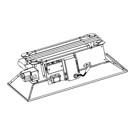
Page 8: R (B,S,M) D Series Dimensions
R (B,S,M) D SERIES DIMENSIONS HANGING The heater can be mounted with the reflector horizontal or angled up to 35º from horizontal. When the heater is to be angle mounted, make sure the gas manifold assembly is on the lower side of the heater. Coil chains (No. 2 or larger) or rigid supports may be used to mount the heater, which must be suspended from a permanent structure with adequate load capacity. -
Page 9: Gas Connections And Regulation
GAS CONNECTIONS AND REGULATION 1. Connect to the supply tank or manifold in accordance with the latest edition of National Fuel Gas Code (ANSI Z223.1), and local building codes. Authorities having jurisdiction should be consulted before the installation is made. 2. - Page 10 5. This appliance is equipped with a snap-opening, combination Certified connections gas valve. The maximum supply pressure to the appliance is recommended to be installed as 14” W.C. or 1/2 P.S.I. If the line pressure is more than the shown, in one plane, and without maximum supply pressure, then use a line regulator as sharp bends, kinks or twists.
-
Page 11: Instructions For Pressure Test Gauge Connection
INSTRUCTIONS FOR PRESSURE TEST GAUGE CONNECTION Supply Pressure 1. The installer will provide a 1/8” N.P.T. plugged tapping, accessible for test gauge connection immediately upstream of the gas supply connection to the heater. Manifold Pressure: Turn the gas valve to the “OFF” position. Remove the 1/8” plug from the combination gas valve at the outlet pressure tap and connect the 1/8”... -
Page 12: Electrical Connections
ELECTRICAL CONNECTIONS 1. All electric wiring shall conform to the latest edition of the National Electrical code (ANSI/NFPA No. 70), or the code legally authorized in the locality where the installation is made. 2. The unit must be electrically grounded in accordance with the National Electrical code (ANSI/NFPA No. 70-latest edition). - Page 13 FIELD CONNECTION AND THERMOSTAT WIRING DIAGRAMS LINE VOLTAGE (120V) THERMOSTAT CONNECTIONS – SINGLE HEATER PER THERMOSTAT LINE VOLTAGE (120V) THERMOSTAT CONNECTIONS – MULTIPLE HEATERS PER THERMOSTAT LOW VOLTAGE (24V) THERMOSTAT CONNECTIONS – MULTIPLE HEATERS PER THERMOSTAT – (POWER SUPPLIED FROM FAN CENTER RELAY) LOW VOLTAGE (24V) THERMOSTAT CONNECTIONS –...
-
Page 14: Ventilation
VENTILATION Where unvented infrared heaters are used, natural or mechanical means shall be provided to supply and exhaust at least 4 cfm per 1000 Btu per hr input of installed heaters. Exhaust openings for removing flue products shall be above the level of the heaters. This heater requires ventilation in the building to dilute the products of combustion and provide fresh air for efficient combustion. -
Page 15: Sequence Of Operation
DIRECT SPARK IGNITION SYSTEM (Ignition Suffix “1”) 1. Turn on the gas supply. 2. Set the thermostat to call for heat. 3. Ignition should occur immediately. 4. If the burner fails to light, or flame is not detected during the first trial for ignition (a period of approximately 10 seconds) the gas valve is de-energized and the control goes through an interpurge delay of approximately 15 seconds before another ignition attempt. -
Page 16: Cleaning And Annual Maintenance
CLEANING AND ANNUAL MAINTENANCE This heater consists of multiple individual atmospheric burners. Due to the variation in tile porosity, there could be color variations between the burners. This is natural and should not be a cause for concern during the initial startup. - Page 17 C) TROUBLESHOOTING CHART TROUBLE POSSIBLE CAUSE SOLUTIONS The supply gas pressure is too low. Check the manifold gas pressure and adjust if necessary. Improper size of gas piping. If you are not sure of the performance, Heater is not glowing use the NFPA 54 gas pipe sizing table.
- Page 18 C) TROUBLESHOOTING CHART Continued Form #43219040 Oct 2013...
-
Page 19: Optional Parabolic Reflector Extension
Section 4 of these instructions) must be closely observed. Please order the Parabolic Reflector Extension Kit using the Part Numbers below: Model No. Parabolic Reflector R (B,S,M) D Series Extension Kit Number RD030, RD033, RD035, RD040 #43822010 RD060, RD066, RD070,... -
Page 20: Replacement Parts Guide
REPLACEMENT PARTS GUIDE PART # DESCRIPTION PART # DESCRIPTION 30333110 Valve VR8205M-2971 @ 10” W.C. – Propane Gas 43908010 Frame Assembly (1 Burner Unit) 30333120 Valve VR8205M-2989 @ 6” W.C. – Natural Gas 43908020 Frame Assembly (2 Burner Unit) 30279000 Transformer AT120B1051 43908030 Frame Assembly... -
Page 21: Warnings Card
WARNINGS CARD This card is furnished with each heater. Additional copies may be ordered under part no. 43344970. Form #43219040 Oct 2013...
Need help?
Do you have a question about the R (B,S,M) D SERIES and is the answer not in the manual?
Questions and answers