Advertisement
ACON-C/CG, PCON-C/CG/CF
First Step Guide
Thank you for purchasing our product.
Make sure to read the Safety Guide and detailed Instruction Manual (DVD) included with the product in addition to this First Step Guide
to ensure correct use.
This Instruction Manual is original.
Warning : Operation of this equipment requires detailed installation and operation instructions which are
provided on the DVD Manual included in the box this device was packaged in. It should be retained
with this device at all times.
A hardcopy of the Manual can be requested by contacting your nearest IAI Sales Office listed at
the back cover of the Instruction Manual or on the First Step Guide.
Using or copying all or part of this Instruction Manual without permission is prohibited.
The company names, names of products and trademarks of each company shown in the sentences are registered trademarks.
Product Check
This product is comprised of the following parts if it is of standard configuration.
If you find any fault in the contained model or any missing parts, contact us or our distributor.
1.
Parts
No.
Part Name
1
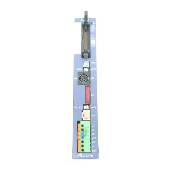
Controller
Accessories
2
I/O cable for positioner
3
First Step Guide
4
Instruction Manual (DVD)
2.
Teaching Tool
The PC software or teaching pendant is necessary to perform setup operations such as position
and parameter settings through teaching or other means.
Prepare any PC software or teaching pendant.
No.
Part Name
1
PC software
2
PC software
3
Teaching pendant
4
Teaching pendant
5
Teaching pendant
6
Teaching pendant (with deadman switch)
Teaching pendant
7
(with deadman switch + TP adapter (RCB-LB-TG))
8
Teaching pendant
9
Teaching pendant (with deadman switch)
10
Simple teaching pendant
11
Data setter
*
The mounting-type touch panel display (RCM-PM-01), which enables data input/change and monitoring, has
also been prepared. However, please note that only some parameters can be set by using it.
* Instruction Manuals related to this product, which are contained in the Instruction Manual
(DVD)
No.
Name
1
ACON-C/CG Controller Instruction Manual
2
PCON-C/CG/CF Controller Instruction Manual
3
PC Software
RCM-101-MW/RCM-101-USB
4
Teaching Pendant
CON-T/TG
5
Teaching Pendant
CON-PT/PD/PG
6
Teaching Pendant
RCM-T/TD
7
Simple Teaching Pendant
RCM-E
8
Data Setter
RCM-P
9
Touch Panel Display
RCM-PM-01
*How to read the model plate
Model
*********
Model
SER NO.
*********
Input
DC24V A
*
Output
Serial number
0-24Vac,3ph,0-333Hz,
Actuator
*****
CAUTION: Connect the wiring correctly and
*How to read the model of the controller
[ACON-C/CG]
A C O N - C - 2 0 I H A - N P - 2 - 0 - A B U
<Series name>
<Type name>
C:
Positioner type with internal
drive-power cutoff relay
CG: Positioner type with external
drive-power cutoff relay
<Actuator characteristics>
[
Motor wattage]
[Encoder type]
2 : 2W
20S : 20W
I: Incremental
5 : 5W
(for RCA-RA3
RCA2-SA4/TA5)
[Option]
10 : 10W
30 : 30W
No description : Standard Type
20 : 20W
HA : High Accel/Decel Type
LA : Less Power consumption Type
[PCON-C/CG/CF]
P C O N - C - 5 6 P I - N P - 2 - 0 - A B U - H
<Series name>
<Model name>
C:
Positioner type with internal drive-power
cutoff relay
CG:
Positioner type with external drive-power
cutoff relay
CF:
High-output positioner type with internal
drive-power cutoff relay
<Actuator characteristics>
20P: 20, square
35P:35, square
28P: 28, square
42P: 42, square
28SP: 28, square
56P: 56, square
(RA3 type only)
86P: 86, square
[Encoder type]
I: Incremental
Tenth Edition
Model
Refer to "How to read the model plate" and "How to
read the model of the controller."
CB-PAC-PIO*** (*** indicates the cable length.)
ME0195
Model
RCM-101-MW
RCM-101-USB
CON-T
CON-TG
CON-PT
CON-PD
CON-PG
RCM-T
RCM-TD
RCM-E
RCM-P
Manual No.
ME0176
ME0170
ME0155
ME0178
ME0227
ME0173
ME0174
ME0175
ME0182
IP20
*
A
properly, use IAI specified cables
or min 60°C Cu wire.
For simple absolute unit
connection
<Power-supply voltage>
0: 24VDC
<I/O flat cable length>
<Input/Output signal pattern>
NP: NPN (Sink type)
PN: PNP (Source type)
DV: DeviceNet Wiring Specification
CC: CC-Link Wiring Specification
PR: PROFIBUS Wiring Specification
CN: CompoNet Wiring Specification
ML: MECHATROLINK Wiring
Specification
High Acceleration
Transport Type
For simple absolute unit
connection
<Power-supply voltage>
0: 24VDC
<I/O flat cable length>
0: No cable
3: 3m
2: 2m
5: 5m
<Input/Output signal pattern>
NP: NPN (Sink type)
PN: PNP (Source type)
DV: DeviceNet Wiring Specification
CC: CC-Link Wiring Specification
PR: PROFIBUS Wiring Specification
CN: CompoNet Wiring Specification
ML: MECHATROLINK Wiring
Specification
10A
Characteristics
(1) This is a position controller which can set 64 positioning points as standard and 512
points at maximum. The position number depends on the PIO pattern which can be
selected by the parameter.
(2) Zone output boundaries can be set for each position.
(3) Acceleration and deceleration can be set separately for each position.
(4) The feed speed to be used in trial run and adjustment can be limited to ensure safety.
(5) The power-saving mode can be selected by the parameter in situations where the
actuator must stand by for a long time period.
ACON Specifications (Controller for RCA2/RCA/RCL Series)
Specification Item
Number of control items
1 axis/unit
Supply voltage
24VDC +10%/-10%
Motor
Actuator
Power
Motor Type
Capacity
*1
RCA/RCA2
20W [Model No. : 20]
20W [Model No. : 20S]
Dedicated to HA3,
HA4 and TA5 Types
RCL
Heating value
Encoder
RCA
All types
resolution
RCA2
RCA2-□□□N
Excluding RCA2-□□□N
RCL
RA1L ꞏ SA1L ꞏ SA4L ꞏ SM4L
RA2L ꞏ SA2L ꞏ SA5L ꞏ SM5L
RA3L ꞏ SA3L ꞏ SA6L ꞏ SM6L
Position number specification 64 points (standard), 512 points (maximum)
Positioning command
* The position number varies depending on the selection of the PIO pattern.
Position data and parameters are saved in nonvolatile memory.
Backup memory
Serial EEPROM can be rewritten 100,000 times. (NOTE 1)
PIO interface
24VDC, input/output
LED indicators
SV (Green) – Servo ON, ALM (Red) – Alarm present
Serial communication
RS485, 1 channel (conforming to the Modbus protocol)
Forced release of
NOM/BK RLS switch (on the front panel)
electromagnetic brake
Cable length
Actuator cable: 20m or less
I/O flat cable: 10m or less
Insulation strength
500VDC, 10M
Surrounding air
0 to 40C
temperature
Surrounding
85%RH or less (non-condensing)
humidity
Surrounding
Refer to Installation Environment
environment
Surrounding
storage
-10 to 65C
temperature
Surrounding
90%RH or less (non-condensing)
storage humidity
10 to 57Hz in XYZ directions/Pulsating amplitude 0.035mm (continuous),
Vibration Durability
0.075mm (intermittent)
57 to 150Hz/4.9m/s
Protection class
IP20
Cooling method
Natural air-cooling
Weight
300g or less
External dimensions
35W x 178.5H x 68.1D (mm)
*1: The rush current, which is approx. 5 to 12 times the
rated current, flows for approx. 1 to 2msec after
power-on. Please note that the rush current value
varies depending on the impedance of the power
line.
*2: The current becomes maximum during the detection
of the excitation phase of the servo motor performed
in the initial servo ON processing after power-on.
(Normal: Approx. 1 to 2sec, Maximum: 10sec)
NOTE 1:
Position data and parameters are written to EEPROM.
Please note that the rewrite limit is around 100,000 times.
Basic Specifications
ACON-C (Internal drive-power cutoff relay type)/
ACON-CG (External drive-power cutoff relay type)
Standard specification/High
acceleration/deceleration
Rated [A]
Peak [A] *2
Rated [A]
10W
1.3
4.4
1.3
4.4
30W
1.3
4.0
1.7
5.1
2W
0.8
4.6
5W
1.0
6.4
10W
1.3
6.4
8.4W
800 Pulse/rev
1048 Pulse/rev
800 Pulse/rev
715 Pulse/rev
855 Pulse/rev
1145 Pulse/rev
2
2
(continuous), 9.8m/s
(intermittent)
As a +24V DC power supply,
select the power supply of the
"peak load support" specification
or one with sufficient capacity.
In particular, in the case of the
unit with the remote sensing
function, the greatest care is
required.
Power-saving
Peak [A] *2
1.3
2.5
1.3
2.5
1.3
2.2
1.7
3.4
Advertisement
Table of Contents

Related Manuals for IAI ACON-C Series


Summary of Contents for IAI ACON-C Series
- Page 1 A hardcopy of the Manual can be requested by contacting your nearest IAI Sales Office listed at ACON Specifications (Controller for RCA2/RCA/RCL Series) the back cover of the Instruction Manual or on the First Step Guide.
-
Page 2: Installation Environment
PCON Specifications (Controller for RCA3/RCP2 Series) Installation Environment PCON-C PCON-CG PCON-CF Specification Item (Internal drive-power (External drive-power (Internal drive-power cutoff relay type) cutoff relay type) cutoff relay type) This product is capable for use in the environment of pollution degree 2 or equivalent. -
Page 3: Connection Diagram
● Driving Source Interruption Relay: External Type Connection Diagram • In the case of the use of a single controller: Teaching Pendant Teaching pendant EMG Switch Host system <PLC> <CON-T> +24V PIO connector Status indicator LEDs ACON-CG, External EMG External EMG PCON-CG reset switch switch... -
Page 4: Starting Procedures
I/O Signals I/O Signals Parameter (PIO) Pattern Selection Function description for I/O Signals Positioning Teaching 256-point 512-point Electromagnetic Electromagnetic mode mode mode mode valve mode 1 valve mode 2 Signal Category Signal Name Function Description Number of Abbreviation Category 64 points 64 points 256 points 512 points... - Page 5 Head Office: 577-1 Obane Shimizu-KU Shizuoka City Shizuoka 424-0103, Japan TEL +81-54-364-5105 FAX +81-54-364-2589 website: www.iai-robot.co.jp/ Technical Support available in USA, Europe and China Head Office: 2690 W. 237th Street, Torrance, CA 90505 TEL (310) 891-6015 FAX (310) 891-0815...
Need help?
Do you have a question about the ACON-C Series and is the answer not in the manual?
Questions and answers