
Related Manuals for Gehl SL3640E


Summary of Contents for Gehl SL3640E
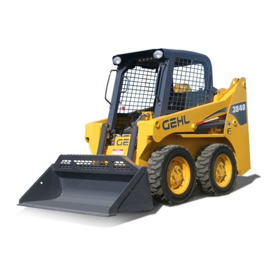
- Page 1 SL3640E Form No. 917334/ SL3840E (EU) BP0310 English SL4240E SL4240E (EU) Skid-Steer Loaders...
- Page 2 WRONG Gehl Company, in cooperation with the American Society of Agricultural Engineers and the Society of Automotive Engineers, has adopted this Safety Alert Symbol to pinpoint precautions which, if not properly followed, can create a safety hazard. When you see this symbol in this...
-
Page 3: Table Of Contents
Index ........81 Loader Model Number Loader Serial Number Engine Serial Number All-Tach™ and Hydraloc™ are trademarks of Gehl Company. ® ® Gehl and Powerview are registered trademarks of Gehl Company. - Page 4 EC DECLARATION OF CONFORMITY Manufacturer: Gehl Company Address: One Gehl Way West Bend, WI 53095 U.S.A. FAX: 262-334-6687 Technical Construction File Location: Attn.: Quality Manager 915 SW 7th St. Madison, SD 57042 U.S.A. Authorized Representative: Gehl Europe GmbH Address: Burgsteinfurter Damm 89...
-
Page 5: Introduction
The Gehl dealership network stands ready to provide you with any assistance you may require, including providing genuine Gehl service parts. All service parts should be obtained from your Gehl dealer. Provide complete information about the part and include the model and serial numbers of your machine. - Page 6 Loader Identification 1. Upright 6. Lift Arm 2. Lift Cylinder 7. Auxiliary Hydraulic Couplers 3. Tires 8. Tilt Cylinders 4. Front Work Lights 9. Attachment Bracket 5. Handholds 1. Engine Cover 5. Roll-Over/Falling Object Protective Structure 2. Tail Lights (ROPS/FOPS) 3.
-
Page 7: Control/Indicator Symbols
Control/Indicator Symbols Hazard Flasher Power Off Power On Engine Start Worklight Worklight w/Flasher Parking Brake Read Operator’s Horn Battery Charge Manual Volume – Full Volume – Half Full Volume – Empty Pre-Heat Diesel Fuel Neutral Lift Point Safety Alert Seatbelt – Lap Only Chaincase Oil Engine Air Filter Engine Oil... - Page 8 Notes 917334/BP0310...
-
Page 9: Safety
For further reference on the safe operation of skid-steer loaders, Gehl Company suggests that equipment owners obtain the Gehl “Skid-Steer Loader Safety” video, which is available through Gehl dealers. In addition, be sure that everyone who operates or works with this machine, whether family member or employee, is familiar with these safety precautions. -
Page 10: Mandatory Safety Shutdown Procedure
To ensure safe operation, replace damaged or worn-out parts with genuine Gehl service parts. Gehl skid-steer loaders are designed and intended to be used only with Gehl attachments or approved referral attachments. Gehl cannot be responsible for operator safety if the loader is used with a non-approved attachment. - Page 11 During Operation Machine stability is affected by: the load being carried, the height of the load, machine speed, abrupt control movements and driving over uneven terrain. DISREGARDING ANY OF THESE FACTORS CAN CAUSE THE LOADER TO TIP, THROWING THE OPERATOR OUT OF THE SEAT OR LOADER, RESULTING IN DEATH OR SERIOUS INJURY.
-
Page 12: Safety Decals
The skid-steer loader has decals that provide safety information and precautions around the loader. These decals must be kept legible. If missing or illegible, they must be replaced promptly. Replacements can be obtained from your Gehl dealer. New equipment must have all decals specified by the manufacturer affixed in their proper locations. - Page 13 Safety Decals inside the ROPS/FOPS 137628 – Located on manual box, operator’s right 137683 – Located on ROPS left panel 137647 – Located on operator’s lower left side 137639 – Located on ROPS left panel 917334/BP0310...
- Page 14 Safety Decals on the outside of the Skid Loader 137637 – Lift arm support device, loader left side 184214 – Under ROPS 137655 – Front of loader 137720 – Front of loader 917334/BP0310...
- Page 15 Safety Decals in the Engine Compartment 137657 – Right of hydraulic filter 137658 – On radiator 917334/BP0310...
- Page 16 ISO-Style (used Internationally) Safety Decals inside the ROPS/FOPS Safety alert: Always follow “Mandatory Safety Shutdown Procedure” in Operator’s Manual. 1 – Lower equipment to ground. 2 – Reduce throttle, stop engine. 3 – Apply parking brake; remove 137842 – Located on manual key.
- Page 17 ISO-Style (used Internationally) Safety Decals on the outside of the Skid-Steer Loader 137844 – Located on front of loader A – Crush hazard: Keep out from under work tool unless lift arm is supported. B – Fall hazard: No riders. Never use work tool as work platform. 137853 –...
- Page 18 ISO-Style (used Internationally) Safety Decals in the Engine Compartment 137845 – Located on cross member for frame A – Safety alert: Keep safety devices in place and in working order. Keep guards, screens and windows in place. B – Fire hazard: Do not smoke while fueling or servicing machine. Clean debris from engine compartment daily to avoid fire.
- Page 19 Product and Component Plate Locations Product and Component Plates 1. Engine plate: with e.g. type designation, product and serial number 2. Operator protective system plate: with e.g. model, certification and operator protection system serial number 3. Product plate: with Product Identification Number and e.g. model/type designation 4.
- Page 20 Notes 917334/BP0310...
-
Page 21: Controls And Safety Equipment
Know how to stop loader operation before starting it. This Gehl loader is designed and intended to be used only with a Gehl attachment or a Gehl-approved referral attachment or accessory. -
Page 22: Operator's Seat
Operator’s Seat The seat is mounted on rails for backward or forward repositioning. A spring-loaded latch handle activates the seat adjustment mechanism. Suspension seat (optional): A weight adjustment knob is provided with this seat for operator comfort. Figure 1 Operator’s Seat 1. -
Page 23: Parking Brake
With the engine running, raise the restraint bar. Move each of the controls. There should be not more than a slight movement of the lift arm, attachment and machine. If there is any significant movement, troubleshoot and correct the problem immediately. Contact your dealer if necessary. Seat Switch With the engine off and the restraint bar lowered, unfasten the seatbelt. -
Page 24: Service
Instead, have someone store the support device for you. Then, contact your Gehl dealer immediately to determine why the lift arm lowers while the keyswitch is OFF. - Page 25 Engagement Always engage the lift arm support device WARNING before leaving the operator’s compartment to work on the loader with the lift arm raised. To engage the lift arm support device: 1. Lower the lift arm fully onto the loader frame. 2.
- Page 26 Disengagement Never leave the operator’s compartment to dis- WARNING engage the lift arm support device with the engine running. To return the lift arm support device to its storage position: 1. Raise the lift arm completely. 2. Stop the engine, remove the key and take it with you.
-
Page 27: Engine Speed Control
Engine Speed Control A right-hand controlled throttle lever is provided on all models for adjusting the engine speed. Move the control forward to increase the engine speed and rear- ward to decrease the engine speed. T-Bar Controls Only: A right-foot operated accelerator pedal is provided to control the engine speed. -
Page 28: Instrument Panel
Instrument Panel The instrument panel contains the following switches and indicators. Symbols on the panel represent various functions and conditions, and are visible only when indicator lamps are on. 1. Hourmeter – Displays the total operating hours on the loader. 2. - Page 29 10. Keyswitch – In a clockwise rotation, these positions are: OFF Position – With the key vertical, power from the battery is disconnected to the controls and instrument panel electrical circuits. This is the only posi- tion the key can be inserted or removed from the keyswitch. ON (or Run) Position –...
-
Page 30: T-Bar Controls
T-Bar Controls The Gehl loader may be equipped with the T-Bar control option. The left T-Bar controls the drive and the right T-Bar con- trols the lift/tilt. Drive Controls Forward, reverse, speed and turning maneuvers are controlled by movement of Figure 9 T-Bar Controls the left T-Bar. -
Page 31: Hand/Foot Controls
Hand/Foot Controls The Gehl loader may be equipped with the hand/foot control option. The handles control the drive and the foot pedals control the lift/tilt. Drive Controls Forward, reverse, speed and turning maneuvers are controlled by movement of the control handles. To go forward, push Figure 10 Hand/Foot Controls both handles forward;... -
Page 32: Auxiliary Hydraulic Controls
Auxiliary Hydraulic Controls Auxiliary hydraulics are used with an attachment that mechanism requiring hydraulic power of its own. Important: Always be sure the auxiliary hydraulic control is in neutral before starting the loader or removing the auxil- iary hydraulic couplers. Couplers are located on the left lift arm. - Page 33 A locking pin locks it in the up position for continuous operation. Figure 13 Hand/Foot Auxiliary Control Attachment Mounting The Gehl loader is equipped with a two-pin All-Tach™ attachment bracket for mounting a bucket or other attach- ment. Two latch levers secure the attach- ment.
- Page 34 Notes 917334/BP0310...
-
Page 35: Operation
CHAPTER 4 OPERATION Before starting the engine and operating the WARNING loader, review and comply with all safety recommendations in the Safety chapter of this manual. Know how to stop the loader before starting it. Also, be sure to fasten and prop- erly adjust the seatbelt and lower the operator restraint bar. -
Page 36: Stopping The Loader
1. Turn the key to the run position. If the preheat light on the right instrument panel comes on, wait until it goes out. 2. Turn the key switch to the start position. 3. Repeat if engine does not start. Stopping the Loader The following procedure is the recommended sequence for stopping the loader: 1. - Page 37 Note: BE SURE the jumper battery is a 12-volt D.C. battery. 1. Turn the keyswitches of both vehicles to OFF, be sure the vehicles are in “neutral” and NOT touching each other. 2. Connect the positive (+) jumper cable to the positive (+) battery terminal on the disabled loader first.
- Page 38 Changing Attachments To prevent unexpected attachment release WARNING from the attachment bracket, be sure to prop- erly secure the latch pins by rotating the latch levers to a horizontal position. The skid-steer loader features a All-Tach™ attaching mechanism for mounting a bucket or other attachment.
-
Page 39: Driving On An Incline
Removing Attachments 1. Tilt the attachment bracket back until the attachment is off the ground. 2. Exercise the MANDATORY SAFETY SHUTDOWN PROCEDURE (page 6). 3. Relieve any hydraulic pressure in the auxiliary and attachment lines. a. Turn the key switch, but do not start the engine. b. -
Page 40: Loading A Bucket
Loading a Bucket Approach the pile with the lift arm fully lowered and the bucket tilted slightly for- ward until the edge contacts the ground. Drive forward, lifting the lift arm and tilting back the bucket to fill it. Back away from the pile. -
Page 41: Scraping With A Bucket
Dumping the Load Into a Box Carry the loaded bucket low and approach the vehicle or bin. Stop your approach as close to the side of the box as possible while allowing for clearance to raise the lift arm and loaded bucket. Next, raise the lift arm until the bucket clears the top of the box and move the loader ahead, to position the bucket over the inside of the... -
Page 42: Lifting The Loader
Lifting the Loader The loader can be lifted using a single-point or four-point lift kit, which is avail- able from your Gehl dealer. WARNING • Before lifting, check the lift kit for proper installation. - Page 43 Storing the Loader If your skid-steer loader is to be stored for a long period of time, the following procedure is suggested: 1. Fully inflate the tires. 2. Lubricate all grease zerks. 3. Check all fluid levels and replenish as necessary. 4.
- Page 44 Notes 917334/BP0310...
-
Page 45: Service
The following areas of component service, replacement and adjustments require special tools and knowledge for proper servicing and should be performed only by your authorized Gehl skid-steer loader dealer: hydrostatic components, hydraulic system gear pump, valves, cylinders, electrical components (other than the battery, circuit breakers). - Page 46 Tilting Back the ROPS/FOPS For service, unbolt the two anchor bolts at the front of the ROPS/FOPS and tilt it back slowly, moving the control handles out of the way. A gas-charged spring helps tilt it back. A self-actuating lock mechanism engages lock...
-
Page 47: Control Handles
074830 Engine Oil Filter Element 137500 Fuel Filter Cartridge 182130 Note: Part numbers may change. Your Gehl dealer will always have the latest part numbers. Adjustments Control Handles The control handles do not require routine adjustment. Refer to the Service Manual for the initial setup procedure. -
Page 48: Drive Chains
Engine Speed Control The throttle cable does not require routine adjustment. Refer to the Service Manual for the initial setup procedure. Besides throttle cable adjustment, the throttle lever friction pad pressure can be readjusted if the throttle lever does not hold its position. Belleville washers and a lock nut on the throttle lever are used for making this adjustment. -
Page 49: Engine Air Cleaner
Figure 26 Grease Every 10 Hours (or daily) 1. Lift arm pivots (2) 2. Lift cylinder pivots (4) 3. Tilt cylinder pivots (2) 4. Attachment Bracket pivots (2) Engine Air Cleaner Important: Failure follow proper filter servicing instructions could result in catastrophic engine damage. - Page 50 3. Replace the outer element. Note: Gehl does not recommend cleaning the outer element. 4. Use a trouble light inside the outer element to inspect for spots, pinholes or ruptures.
-
Page 51: Engine Service
Reinstallation 1. Check the inside of the housing for any damage that may interfere with the elements. 2. Be sure that the element sealing surfaces are clean. 3. Insert the element(s), making sure that they are seated properly. 4. Secure the cover to the housing with clamps. 5. -
Page 52: Specifications
Changing Engine Oil and Filter 1. Run the engine until it is at operating temperature. Stop the engine. Remove the rear belly pan. 2. Remove the drain plug. 3. From engine compartment, remove the oil filter. Clean the filter sealing surface. 4. -
Page 53: Alternator/Fan Belt
Servicing Water Separator Periodically check for water in water separator by checking level of float in water separator bowl. If water is present: 1. Shut off the fuel supply by turning the fuel shutoff valve on top of the water separator. -
Page 54: Hydraulic System
Hydraulic System Checking Hydraulic Oil Level The loader has a dipstick located in the engine compartment. Check the fluid level with the lift arm lowered and the attachment on the ground. When hydraulic fluid is required, allow the system to cool. Slowly remove the oil fill cap, allowing the pressure to dispel before removing the cap completely. - Page 55 8. Stop the engine and check for leaks at the filter and reservoir drain plug. 9. Check the fluid level and add fluid if needed. Cooling Systems Important: Check the cooling system every day to prevent overheating, loss of performance or engine damage. Checking Coolant Level 1.
-
Page 56: Checking And Adding Oil
Note: Protect the cooling system by adding premixed 50% water and 50% ethy- lene glycol to the system. This mixture will protect the cooling system to -34°F (-36°C). 5. Fill the radiator fully and the recovery tank half full with the premixed coolant. -
Page 57: Bucket Cutting Edge
Bucket Cutting Edge The bucket cutting edge should be replaced when it is worn to within 1 in. (25 mm) of the bucket body. Wheel Nuts Wheel nut torque must be checked before initial operation and every two hours thereafter until the wheel mounting hardware torque stabilizes at the recommended setting of 120-130 ft-lbs (161-175 N·m). -
Page 58: Checking Tire Pressure
Checking Tire Pressure Inflation Pressure Tire Size 10 x 16.5 8-ply Heavy-Duty Flotation 27 x 8.5 –15 8-ply Heavy-Duty 27 x 10.5 – 15 8-ply Heavy-Duty 6.5 x 16 – 5.50 Solid Rubber 7.00-15 SS Chevron Narrow 8-ply Correct tire pressure should be maintained for all tires to enhance operating stability and extend tire life. - Page 59 Battery Before servicing the battery or electrical WARNING system, be sure the battery disconnect switch (if equipped) is in the “OFF” position. If not equipped with a discon- nect switch, disconnect the ground (-) terminal from battery. The battery on the loader is a 12-volt, wet-cell battery. To access the battery, open the rear door and lift the engine cover.
- Page 60 Notes 917334/BP0310...
-
Page 61: Troubleshooting
CHAPTER 6 TROUBLESHOOTING Electrical System Problem Possible Cause Remedy Battery disconnect switch is Turn battery disconnect OFF. switch to ON. 15-ampere breakers tripped. Check circuit and locate trouble before resetting breaker. Entire electrical Main wiring harness Check main harness system does not connectors at rear of ROPS connectors. -
Page 62: Electrical System
Electrical System Problem Possible Cause Remedy Seat or restraint bar switch Replace switches as needed. malfunctioning or not If engine still doesn’t start, activated. contact your dealer. Poor connections to starter Verify relay connections. relay in instrument panel. Battery terminals or cables Clean terminals, cables and loose or corroded. - Page 63 Engine Problem Possible Cause Remedy Engine cranking speed too Battery requires recharging slow. or replacing, or, in cold temperatures, pre-warm the engine. Auxiliary valve engaged. Return control valves to neutral. Fuel tank empty or faulty fuel Refill fuel tank. Replace fuel gauge sender.
-
Page 64: Hydrostatic System
Hydrostatic System Problem Possible Cause Remedy Hydraulic oil viscosity is too Allow longer warm-up or heavy. replace existing oil with the No response from proper viscosity oil. either hydrostatic drive or the lift/tilt Hydraulic oil supply is too Check for low oil level in systems. - Page 65 Hydrostatic System Problem Possible Cause Remedy Drive system overloaded Improve efficiency of continuously. operation. Lift/tilt or auxiliary system Improve efficiency of overloaded continuously. operation. Drive motor(s) or hydrostatic Contact your dealer. Hydrostatic drive pump(s) have internal is overheating. damage or leakage. Oil cooler fins plugged with Clean oil cooler fins.
- Page 66 Hydrostatic System Problem Possible Cause Remedy Hydraulic oil viscosity is too Allow longer warm-up or heavy. replace existing oil with the proper viscosity oil. Air in hydraulic system. Cycle lift and tilt cylinders to maximum stroke and Hydrostatic (drive) maintain pressure for a short system is noisy.
- Page 67 Hydraulic System Problem Possible Cause Remedy Hydraulic oil viscosity is too Allow longer warm-up or heavy. replace with proper viscosity oil. Hydraulic oil level is low. Check oil level in reservoir. If oil is low, check for an Lift/Tilt controls external leak.
- Page 68 Hydraulic System Problem Possible Cause Remedy Self-leveling valve Contact your dealer. Bucket does not level misadjusted or on the lift cycle. malfunctioning. Seat or restraint bar switch Check electrical connections malfunction. to the switches. Replace as needed. Air in the hydraulic system. Cycle lift/tilt cylinders to Jerky lift arm and maximum stroke and...
- Page 69 Hydraulic System Problem Possible Cause Remedy Lift solenoid valve could be Check electrical connections malfunctioning. to lift solenoid and repair connections as needed. If lift Lift arm does not solenoid valve is still not raise, bucket tilt functioning properly, contact works properly.
- Page 70 Notes 917334/BP0310...
-
Page 71: Maintenance Schedule
CHAPTER 7 MAINTENANCE SCHEDULE This Maintenance Interval Chart was developed to match the Service chapter of this manual. Detailed information on each service procedure can be found in the Service chapter. A Maintenance Log follows the chart for recording the mainte- nance performed. -
Page 72: Maintenance Log
Maintenance Log Date Hours Service Procedure 917334/BP0310... - Page 73 Maintenance Log Date Hours Service Procedure 917334/BP0310...
- Page 74 Notes 917334/BP0310...
-
Page 75: Specifications
CHAPTER 8 SPECIFICATIONS Loader Specifications Specification 3640E/3840E (EU) 4240E Operating Weight 4000 lbs. (1814 kg) 4600 lbs.(2087 kg) Shipping Weight 3515 lbs. (1594 kg) 4065 lbs. (1844 kg) 1050 lbs. (476 kg) 1350 lbs. (612 kg) Rated Operating Load (capacity) Engine Make Yanmar... -
Page 76: Standard Features
Standard Features Choice control types: Adjustable Seatbelt T-Bar or Hand/Foot Lift Arm Support Device Fuel Gauge Hydraloc™ System – Brakes and All-Tach™ Attachment System Interlock for Starter, Lift/Tilt (Universal-Type) Cylinders, Auxiliary Hydraulics, and Wheel Drives Warning Lamps and Buzzer – Dual Front and Rear Work Lights Engine and Hydraulic Oil Temperature... - Page 77 Dimensional Specifications SL3640E & 10.5 ft (0.3 m ) Bucket w/27 x 8.5 x 15 Tires SL3840E (EU) inches A Overall Operation Height – Fully Raised 139.6 3546 B Height to Hinge Pin – Fully Raised 108.1 2746 C Overall Height – to ROPS 70.3...
- Page 78 Dimensional Specifications 11.7 ft (0.3 m ) Bucket SL4240E w/10 x 16.5 Tires inches A Overall Operation Height – Fully Raised 141.1 3584 B Height to Hinge Pin – Fully Raised 110.0 2794 C Overall Height – to ROPS 71.9 1826 D Overall Length –...
-
Page 79: Table Of Common Materials And Densities
Capacities and Ratings Note: Use the Table of Common Materials and Densities (page 76) for selecting the appropriate bucket. Dirt/Construction Buckets Rated Operating Capacity Description Weight SL3640E/ SL4240E SL3840E (EU) 235 lbs. 1095 lbs. 1383 lbs. 55 in./10.5 ft (1397 mm/0.30 m... -
Page 80: Table Of Common Materials And Densities
Table of Common Materials and Densities Density Material lbs/ft kg/m Ashes 35-50 560-800 Brick-common 1792 Cement 1760 Charcoal Clay, wet-dry 80-100 1280-1600 Coal 53-63 848-1008 Concrete 1840 Cinders Coal-anthracite 1504 Coke Earth-dry loam 70-90 1121-1442 Earth-wet loam 80-100 1281-1602 Granite 93-111 1488-1776 Gravel-dry... - Page 81 Bucket Selections To use the table, find the material name and see what its maximum density is. Then, multiply the loader rating of the attachment by the material density to determine if the attachment can safely be used. See page 75 for a listing of attachments and their loader ratings.
- Page 82 Notes 917334/BP0310...
-
Page 83: Torque Specifications
CHAPTER 9 TORQUE SPECIFICATIONS Use these torque values when tightening hardware (excluding: locknuts, and self-tapping, thread forming, and sheet metal screws) unless otherwise specified. UNIFIED GRADE 2 GRADE 5 GRADE 8 NATIONAL LUBED LUBED LUBED THREAD 8-32 8-36 10-24 10-32 1/4-20 1/4-28 5/16-18... - Page 84 GEHL COMPANY WARRANTY GEHL COMPANY, hereinafter referred to as Gehl, warrants new Gehl equipment to the Original Retail Purchaser to be free from defects in material and workmanship for a period of twelve (12) months from the Warranty Start Date.
-
Page 85: Index
INDEX Cooling System ... . Check Coolant Level ..Accessory Plug ... . Clean ....Adjustments . - Page 86 MAINTENANCE SCHEDULE . Table of Common Materials & Densi- ties ....Maintenance Log ..Table of Common Materials and Densities .
- Page 87 WRONG WRONG Never exceed rated Always carry attachment operating load. as low as possible. Do not travel or turn with the lift arm raised. Load, unload and turn on flat level surface. WRONG WRONG Never carry riders. Never modify equipment. Keep bystanders away Use only attachments from work area.
-
Page 88: California Proposition 65 Warnings
State of California to cause cancer and birth defects or other reproductive harm. Wash hands after handling battery. ® Gehl Company One Gehl Way, P.O. Box 179, West Bend, WI 53095-0179 U.S.A. www.gehl.com © 2010 GEHL COMPANY 917334/BP0310 All Rights Reserved.
Need help?
Do you have a question about the SL3640E and is the answer not in the manual?
Questions and answers
4 автоматических выключателя на панели приборов, за что они отвечают