Table of Contents
Advertisement
Advertisement
Table of Contents

Related Manuals for Gehl V270


Summary of Contents for Gehl V270
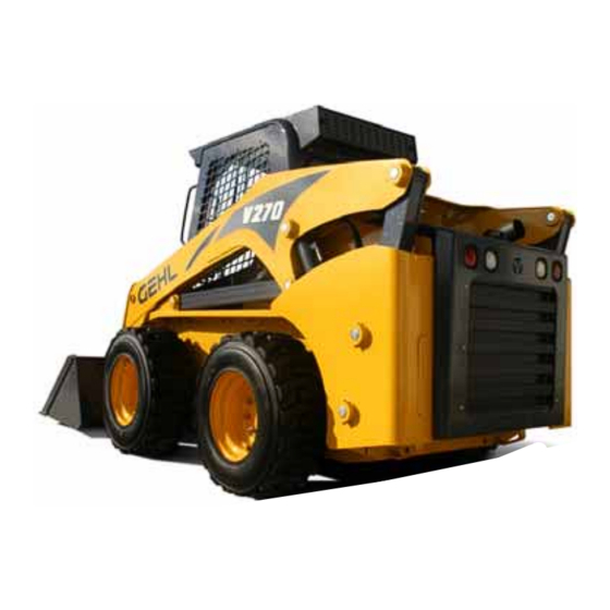
- Page 1 V270 Form No. 917387 V270 (EU) BP0310 English Skid-Steer Loader...
- Page 2 WRONG Gehl Company, in cooperation with the Society of Automotive Engineers, has adopted this Safety Alert Symbol to pinpoint precautions which, if not properly followed, can create a safety hazard. When you see this symbol in this manual or on the machine itself, you are...
-
Page 3: Table Of Contents
Index ........93 Loader Model Number Loader Serial Number Engine Serial Number Power-A-Tach, Hydraloc and Hydraglide are trademarks of Gehl Company. Gehl and Powerview are registered trademarks of Gehl Company. - Page 4 EC DECLARATION OF CONFORMITY Manufacturer: Gehl Company Address: One Gehl Way West Bend, WI 53095 U.S.A. FAX: 262-334-6687 Technical Construction File Location: Attn.: Quality Manager 915 SW 7th St. Madison, SD 57042 U.S.A. Authorized Representative: Gehl Europe GmbH Address: Burgsteinfurter Damm 89...
-
Page 5: Introduction
The Gehl dealership network stands ready to provide any assistance that may be required, including providing genuine Gehl service parts. All service parts should be obtained from your Gehl dealer. Provide complete information about the part and include the model and serial numbers of the machine. -
Page 6: Loader Identification
Loader Identification 1. Lift Arm 5. Attachment Bracket 2. Restraint Bar 6. Tires 3. Front Work Lights 7. Lift Arm Support Device 4. Tilt Cylinders 1. Lift Cylinder 3. Engine Cover 2. Roll-Over/Falling Object 4. Rear Work Lights Protective System 5. -
Page 7: Control/Indicator Symbols
Control/Indicator Symbols Electrical Power Power Off Power On Engine Start Battery Charge Worklight w/Tail Worklight Safety Alert Hazard Flasher Fasten Seatbelt Lights Horn Read Operator’s Volume – Full Volume – Half Full Volume – Empty Manual High – Low Neutral Forward Reverse Parking Brake... - Page 8 Notes 917387/BP0310...
-
Page 9: Safety
Gehl ALWAYS considers the operator’s safety when designing its machinery, and guards exposed moving parts for the operator’s protection. However, some areas cannot be guarded or shielded in order to assure proper operation. -
Page 10: Mandatory Safety Shutdown Procedure
To ensure safe operation, replace damaged or worn-out parts with genuine Gehl service parts. Gehl loaders are designed and intended to be used only with Gehl attach- ments and approved attachments. To avoid possible personal injury, equip- ment damage and performance problems, use only attachments that are approved for use on and within the operating capacity of the machine. - Page 11 During Operation Machine stability is affected by: load being carried, height of the load, machine speed, abrupt control movements and driving over uneven terrain. DISREGARDING ANY OF THESE FACTORS CAN CAUSE THE LOADER TO TIP, THROWING THE OPERATOR OUT OF THE SEAT OR LOADER, RESULTING IN DEATH OR SERIOUS INJURY.
-
Page 12: Safety Decals
These decals must be kept legible. If missing or illegible, they must be replaced promptly. Replacements can be obtained from your Gehl dealer. If there is a decal on a part that is to be replaced, be sure that the decal is applied to the replacement part. - Page 13 ANSI-Style Safety Decals inside the ROPS/FOPS 242582 – Located behind operator’s left shoulder 242236 – Located on upper left instrument panel 242260 – Located 242397 – Located on upper left on lower left instrument panel instrument panel 917387/BP0310...
- Page 14 ANSI-Style Safety Decals on the outside of the Loader 137655 – Located on front of loader 132166 – Located on rear window emergency exit 137755 – Located on lift arm crossmember (manual hitch loaders only) 139101 – Located on lift arm crossmember (power hitch loaders only) 917387/BP0310...
- Page 15 ANSI-Style Safety Decals on the outside of the Loader 137637 – Located on lift arm support device 184214 – Located under the ROPS/FOPS 917387/BP0310...
- Page 16 ANSI-Style Safety Decals in the Engine Compartment 137657 – Located on radiator 137658 – Located on fan shroud 917387/BP0310...
- Page 17 ISO-Style (used Internationally) Safety Decals inside the ROPS/FOPS Safety alert: Always follow “Mandatory Safety Shutdown Procedure” in Operator’s Manual. 1 – Lower equipment to ground. 2 – Reduce throttle, stop engine. 3 – Apply parking brake; remove 242568 – Located behind key.
- Page 18 ISO-Style (used Internationally) Safety Decals on the outside of the Loader 137844 – Located on front of loader A – Crush hazard: Keep out from under work tool unless lift arm is supported. B – Fall hazard: No riders. Never use work tool as work platform. 132166 –...
- Page 19 ISO-Style (used Internationally) Safety Decals on the outside of the Loader Crush hazard: Hose removal or component failure can cause lift arm to drop. Always use lift arm support device when leaving lift arm raised for service. 137848 – Located on the lift arm locking device 184711 –...
- Page 20 ISO-Style (used Internationally) Safety Decals in the Engine Compartment 137845 – Located on radiator A – Safety alert: Keep safety devices in place and in working order. Keep guards, screens and windows in place. B – Fire hazard: Do not smoke while fueling or servicing machine. Clean debris from engine compartment daily to avoid fire.
- Page 21 Product and Component Plate Locations Product and Component Plates 1. Operator protective system plate: with, e.g., model, certification and operator protective system serial number 2. Seat plate according to ISO 7096 3. Product plate: with Product Identification Number and, e.g., model/type designation 4.
- Page 22 Notes 917387/BP0310...
-
Page 23: Controls And Safety Equipment
Know how to stop loader operation before starting it. This Gehl loader is designed and intended to be used only with Gehl attachments or Gehl-approved referral attach- ments or accessories. Gehl cannot be responsible for operator safety if the loader is used with non-approved attachments. -
Page 24: Safety Interlock System
Operator’s Seat The seat is mounted on rails for rearward and forward repositioning. A spring- loaded lever activates the seat position adjustment mechanism. Suspension seat: A weight adjustment knob is provided for individual operator adjustment. Air Suspension Seat: Adjust air suspen- sion seat by pushing in the knob on the air seat to increase the amount of suspension. -
Page 25: Parking Brake
Note: The auxiliary hydraulic circuit can be detented in the “on” position for continuous operation with the restraint bar raised and operator out of the seat. (See Auxiliary Hydraulic Controls, page 36.) Testing the Safety Interlock System Before exiting the machine, check the safety interlock system for proper opera- tion: Restraint Bar With the engine running, raise the restraint bar. -
Page 26: Lift Arm Support Device
If the valve does not hold the lift am and it begins to lower do not leave the operator’s compartment. Instead, lower the lift arm and exit the machine. Then, contact your Gehl dealer immediately to determine why the lift arm lowers while the key switch is OFF. -
Page 27: Accessory Plug
Figure 4 Lift Arm Support ator’s compartment. Instead, have Device Storage Location an assistant remove the support device for you. Then, contact your Gehl dealer determine reason why the lift arm lowers while the key switch is in the OFF position. -
Page 28: Work Lights
Dome Light The dome light is located on the right side of the ROPS/FOPS headliner. Push on the dome light to switch it on. Work Lights Loaders have two sets of work lights. The front work lights are located at the top of the ROPS/FOPS. - Page 29 With joystick controls, a foot pedal is pro- vided as a secondary throttle, which can be used to override the engine speed con- trol. If the foot throttle is released, the engine will return to the speed set by the engine speed control.
- Page 30 To prevent unexpected release of the attach- WARNING ment from the hitch, be sure to secure the latch pins by rotating the levers all the way to the stops. ® Power-A-Tach System Two switches are used to operate the Power-A-Tach System hitch. The Power-A- Tach switch on the left instrument panel energizes the system.
- Page 31 Indicator and Warning Lamp Display Figure 9 Indicator and Warning Lamp Display The instrument panels and the indicator and warning lamp display (Figure 9) contain the switches and indicator lamps. Symbols on the indicator lamps are vis- ible only when the indicator lamp are on. Indicator and Warning Lamp Display 1.
- Page 32 9. Float Indicator – Lights when the lift arm “float” function is activated. 10. Pre-heat Indicator Lamp – Lights when the (automatic) pre-heat is active. During normal operation this indicator should be OFF. 11. Fasten Seatbelt – A momentary visual (and audible) indicator to remind the operator to fasten the seatbelt(s).
-
Page 33: Bp0310
Instrument Panels Left Panel 1. Indicator and Warning Lamp Display – See page 27. 2. Rotating Beacon/Strobe Switch (optional) – Controls the warning lamp (strobe or bea- con). 3. Hazard/Flasher Switch (optional) – Con- trols hazard/flasher. 4. High/Low Beam Switch (EU optional) – Controls road head lights between main/ upper beams and dimmed/lower beams. - Page 34 8. Light Switch – Controls all the lights on the loader. Symbols denote the four positions of the light switch. In a clockwise direction these are: Domestic Machines: – Tail lights (position lights), if the – machine has the optional flasher kit, the lights will be on steady.
- Page 35 Right Panel 1. Fuel Level Gauge – Displays the amount of fuel in the tank. 2. Engine Coolant Temperature Gauge – Displays the temperature of the engine coolant. 3. Parking Brake Switch – Used to manu- ally apply the parking brake. Lights when the parking brake is applied.
-
Page 36: Joystick Controls
Joystick Controls The loader may be equipped with dual joystick controls, (Figure 13). The left joystick controls the drive, and the right joystick controls the lift/tilt. Drive Controls Forward, reverse, speed and turning maneuvers are accom- plished by movement of the left joystick. -
Page 37: Lift/Tilt Control
Lift/Tilt Control Moving the lift arm and tilting the attachment are accomplished by movement of the right joystick. To raise the lift arm, pull the control straight rearward; to lower the lift arm, push the control straight forward. To tilt the attachment for- ward and downward, move the control to the right;... -
Page 38: Hand/Foot Controls
Hand/Foot Controls The loader may be equipped with hand/foot controls (Figure 14). The handles control the drive and the foot pedals control the lift/tilt. Drive Controls Forward, reverse, speed and turning maneuvers are accom- plished by movement of the con- trol handles. -
Page 39: Lift/Tilt Controls
Lift/Tilt Controls Moving the lift arm and tilting the attachment are accomplished by movement of the foot pedals. The left pedal raises and lowers the lift arm; the right pedal tilts the attachment. To raise the lift arm, push down on the back of the left pedal with your left heel;... - Page 40 Auxiliary Hydraulic System Auxiliary hydraulics are used with attachments that have a mechanism requiring hydraulic power. Always be sure the auxiliary hydraulic control is in neu- WARNING tral before starting the loader or disconnecting the auxil- iary hydraulic couplers. Standard-Flow Auxiliary Hydraulic Control Loaders are equipped with a standard-flow auxiliary hydraulic system with flat- face couplers.
-
Page 41: Operation
CHAPTER 4 OPERATION Before starting the engine and operating the WARNING loader, review and comply with all safety rec- ommendations in the Safety chapter of this manual. Know how to stop the loader before starting it. Also, be sure to fasten and prop- erly adjust the seatbelt(s) and lower the operator restraint bar. -
Page 42: Stopping The Loader
After the engine starts, allow a five minute low idle warm-up period before oper- ating the controls. Important: If the indicator warning lamps do not go off, stop the engine and investigate the cause. Cold-Starting If the temperature is below 32°F (0°C), the following is recommended to make starting the engine easier: Replace the engine oil with SAE 10W-30 oil, or lighter as recommended by the viscosity chart;... -
Page 43: Parking The Loader
Note: The skid-steer loader is equipped with a spring-applied automatic parking brake. The parking brake is applied when the operator lifts the restraint bar, leaves the operator’s seat or shuts off the engine, or actuates the parking brake switch. Parking the Loader Park the loader away from traffic on level ground. - Page 44 7. After the disabled loader is started and running smoothly, have the second person remove the jumper cables [negative (-) jumper cable first] from the jumper vehicle’s battery and then from the disabled loader, while being care- ful NOT to short the two cables together. Allow sufficient time for the skid-steer loader battery to build up a charge before operating the loader or shut off the engine.
- Page 45 Connecting Auxiliary Hydraulic Couplings Note: With the engine off, key in the ON position and the restraint bar down, the auxiliary hydraulic control can be moved to relieve any pressure in the hydraulic system. Because the auxiliary hydraulics system is controlled using pilot pres- sure stored in an accumulator, the engine must have been run recently.
-
Page 46: Driving On An Incline
Using a Bucket Always maintain a safe distance from electric WARNING power lines and avoid contact with any elec- trically charged conductor or gas line. Accidental contact or rup- ture can result in electrocution or an explosion. Contact the “Call Before You Dig”... -
Page 47: Scraping With A Bucket
Dumping the Load onto a Pile Carry a loaded bucket as low as possible until the pile is reached. Gradually stop forward motion and raise the lift arm high enough so that the bucket clears the top of the pile. Then, slowly move the loader ahead to position the bucket to dump the material on top of the pile. -
Page 48: Vibration Information
Leveling the Ground Drive the loader to the far edge of the area to be leveled. Tilt the bucket forward to position the bucket cutting edge at a 30 to 45 degree angle to the surface being leveled. Then place the lift arm into “float”... - Page 49 Improper operating techniques, such as driving too fast Incorrect adjustment of the seat and controls Other physical activities while using the machine Vibration Measurement and Actions The vibration directive places the responsibility for compliance on employers. Actions that should be followed by employers include: Assess the levels of vibration exposure.
-
Page 50: Vibration Levels
For additional vibration data, refer to ISO TR 25398. The data above indicates that Gehl skid-steer loaders, when used in a similar manner as described above, do not exceed the limit value for Whole-Body Vibra- tions, and can therefore be operated by one operator for at least 8 hours per day. -
Page 51: Highway Travel
Highway Travel If it becomes necessary to move the loader a long distance, use a properly rated trailer. (See Transporting the Loader on page 48.) For short distance highway travel, attach an SMV (Slow-Moving Vehicle) emblem (purchased locally) to the back of the loader. - Page 52 4. Add stabilizer to the fuel per the fuel supplier’s recommendations. 5. Remove the battery, charge fully and store in a cool, dry location. 6. Protect against extreme weather conditions such as moisture, sunlight and temperature. Transporting the Loader Park the truck or trailer on a level surface. Be WARNING sure the vehicle and its ramps have the weight capacity to support the loader.
-
Page 53: Lifting The Loader
Lifting the Loader The loader can be lifted using a single-point or four-point lift kit, which are avail- able from your Gehl dealer. WARNING • Before lifting, check the lift kit for proper installation. • Never allow riders in the operator’s compartment while the loader is lifted. - Page 54 Notes 917387/BP0310...
-
Page 55: Service
The following areas of component service, replacement and adjustments require special tools and knowledge for proper servicing and should be performed only by your authorized Gehl skid-steer loader dealer: hydrostatic drive components, hydraulic system pumps, valves, hydraulic cylinders, electrical components (other than battery, fuses or relays). -
Page 56: Replacement Parts
Fresh Air Intake Filter (heater option) 242832 (2 per) Recirculation Air Filter (heater option) Note: Part numbers may change. Your Gehl dealer will always have the latest part numbers. Important: To ensure continued warranty coverage, use only genuine Gehl replacement filters. - Page 57 2. Using a jack or hoist capable of lifting the fully-equipped weight of the loader (with all attached options), lift the rear of the loader until the rear tires are off the ground. 3. Stack wooden blocks under the flat part of the loader chassis. They should run parallel with, but not touch, the rear tires.
-
Page 58: Control Handles
Tilting Back the ROPS/FOPS A manual hydraulic pump in the engine compartment is used to tilt back the ROPS/ FOPS. The pump handle is stored in the rear door. A manual lock mechanism engages to lock the ROPS/FOPS in a tilted-back position. - Page 59 Important: Build-up of foreign materials in these areas can interfere with the operation of the loader, cause component damage or become a fire hazard. Lubrication Listed below are the temperature ranges and types of lubricants for this machine. Refer to the separate engine manual for more information regarding engine lubri- cants, quantities and grades required.
- Page 60 50/250 Figure 29 Service Locations 1000 10 Hours 500 Hours Hours (or Lubrication Procedure (or Daily) Hours (or Yearly) Yearly) Check Engine Oil Level (page 62) Check Hydraulic Oil Level (page 67) Grease Hitch, Hitch-related Cylinder Pivots and Latch Pins (page 55) Check Oil Level in Chaincases (page 57) Change Engine Oil and Filter (page 62) Change Hydraulic Oil Filter (page 67)
-
Page 61: Checking And Adding Oil
Chaincases There is a chaincase on each side of the loader. Refer to the Maintenance Interval Chart (page 81) for change intervals. Refer to the Lubrication chart (page 56). Checking and Adding Oil 1. Park the loader on a level surface. Stop the engine. 2. -
Page 62: Drive Chains
Drive Chains Drive chains are located in the chaincase on each side of the machine. Refer to the Maintenance Interval Chart (page 81) for tension check interval. Checking Chain Tension 1. Raise the loader following the Loader Raising Procedure (page 52). 2. - Page 63 The outer element should be replaced only when the restriction indicator turns red. The inner element should be replaced every third time the outer element is replaced, unless the outer element is damaged or the inner element is visibly dirty. Along with a daily check of the restriction indicator, check that the air cleaner intake hose and clamps, and the mounting bracket hardware are properly secure.
- Page 64 Inner Element Note: Replace the inner element only if it is visibly dirty or if the outer element has been replaced three times. 1. Before removing the inner element from the housing, clean out any dirt built up in the housing. Leave the inner element installed during this step to pre- vent debris from entering the engine intake manifold.
-
Page 65: Engine Service
Engine Service Figure 33 Engine Service Components 1. Muffler 6. Water Separator 2. Air Cleaner 7. Fuel Filter 3. Coolant Recovery Tank 8. Engine Oil Drain 4. Radiator/Cooler 9. Engine Oil Fill Cap 5. Engine Oil Filter 10. Engine Oil Dipstick 917387/BP0310... -
Page 66: Changing Fuel Filter
Refer to the Maintenance Interval chart (page 81) for change intervals. Refer to the Replacement Parts chart (page 52) for filter part numbers. Refer to the Engine Operator’s Manual for detailed engine information. Checking Engine Mounting Hardware All bolts that secure the engine mounting brackets to the engine and the loader frame should be checked and re-torqued as necessary. - Page 67 Checking the Water Separator The separator is located between the fuel tank and main fuel filter and is used to remove finely dispersed water in diesel fuel. Check on a daily basis and drain if necessary. Water can be drained from the separator by opening the valve located at the bottom of the separator bowl.
- Page 68 Engine Diagnostic Chart (cont.) Action/ Number Failure detection Item Operation when failure occurs condition for Category conditions recovery flashes Coolant tempera- Sensor voltage is Engine runs with a coolant temperature of Correct failure. Always ture sensor failure 4.8 V or more, or 30°C.
- Page 69 Engine Diagnostic Chart (cont.) Action/ Number Failure detection Item Operation when failure occurs condition for Category conditions recovery flashes Backup speed Engine start signal Engine continues to run while main speed Turn key off. Default to sensor failure (E8) is on, but the sensor is used.
- Page 70 Engine Diagnostic Chart (cont.) Action/ Number Failure detection Item Operation when failure occurs condition for Category conditions recovery flashes 19 Sensor 5V failure Monitoring voltage Engine runs normally. Turn key off. Always is approx. 0 V. enable Monitoring voltage is 4.5 V or less. Monitoring voltage is 5.5 V or more.
-
Page 71: Hydraulic System
Hydraulic System Refer to the Maintenance Interval Chart (page 81) for service intervals. Refer to the Replacement Parts chart (page 52) for filter part numbers. Before servicing the hydraulic system, be WARNING sure the lift arm is lowered. Checking Hydraulic Oil Level The loader has a sight gauge located at the back wall of the skid-steer loader engine compartment (Figure 36). -
Page 72: Bucket Cutting Edge
Changing Hydraulic Oil The hydraulic oil must be replaced if it becomes contaminated, after major repairs and after 1000 hours or one year of use. 1. Install a catch pan of sufficient capacity under the oil reservoir. See page 55. 2. -
Page 73: Cooling System
Cooling System Important: Check the cooling system daily to prevent overheating, loss of perfor- mance and engine damage. Cleaning the Cooling System Allow sufficient time for the oil radiator to WARNING cool before working on or near it. Parts get extremely hot during operation and can burn you. -
Page 74: Checking Tire Pressure
Checking Tire Pressure Correct tire pressure should be maintained to enhance operating stability and extend tire life. Refer to the chart below for proper inflation pressures. Inflation Pressure Tire Size 12 x 16.5 10-ply Heavy-Duty Flotation 14 x 17.5 12-ply Heavy-Duty Flotation 12 x 16.5 12-ply Severe-Duty... -
Page 75: Electrical System
Electrical System Fuse Panel The main fuse panel is located behind the cover in the operator’s compartment above the chaincase on the left side of the operator’s foot area. The loader also has a distribution panel located above and to the front of the battery in the engine compartment. - Page 76 Notes 917387/BP0310...
-
Page 77: Troubleshooting
CHAPTER 6 TROUBLESHOOTING Electrical System Problem Possible Cause Remedy Battery disconnect switch is Turn battery disconnect in OFF position. switch to ON. Main wiring harness Check main harness connectors at rear of ROPS/ connectors. FOPS not properly plugged in. Entire electrical Faulty keyswitch. - Page 78 Electrical System Problem Possible Cause Remedy Battery terminal or cables Clean terminal, cables and loose or corroded. retighten Battery discharged or Recharge or replace battery. defective. Seat or restraint bar switch Contact your dealer. malfunctioning or not actuated. Ignition wiring, seat switch, Check wiring for poor restraint bar switch, etc.
- Page 79 Engine Problem Possible Cause Remedy Engine cranking speed too Battery requires recharging slow. or replacing, or, in cold temperatures, pre-warm the engine. Auxiliary valve engaged. Return control valves to neutral. Fuel tank empty. Refill fuel tank. Engine turns over but will not start. Fuel valves turned off.
-
Page 80: Hydrostatic Drive System
Hydrostatic Drive System Problem Possible Cause Remedy Hydraulic oil viscosity too Allow longer warm-up or heavy. replace oil with proper No response from viscosity oil. either hydrostatic drive or the lift/tilt Hydraulic oil too low. Check for low oil level in systems. - Page 81 Hydraulic System Problem Possible Cause Remedy Hydraulic oil viscosity too Allow longer warm-up or heavy. replace oil with proper viscosity oil. Air in hydraulic system. Cycle lift and tilt cylinders to maximum stroke and Hydrostatic (drive) maintain pressure for short system is noisy.
- Page 82 Hydraulic System Problem Possible Cause Remedy Low engine speed. Operate engine at higher speed. Hydraulic oil viscosity too Allow longer warm-up or heavy. replace with proper viscosity oil. Hydraulic oil level low. Check oil level in reservoir. If oil is low, check for an external leak.
- Page 83 Hydraulic System Problem Possible Cause Remedy Oil leading past lift cylinder Contact your dealer. seals (internal or external). Oil leaking past lift spool in Contact your dealer. Lift arm does not control valve. maintain raise Self-leveling valve Contact your dealer. position with left malfunctioning.
- Page 84 Notes 917387/BP0310...
-
Page 85: Maintenance
CHAPTER 7 MAINTENANCE This Maintenance Interval chart was developed to match the Service chapter of this manual. Detailed information on each service procedure is in the Service chapter. A Maintenance Log follows this chart for recording maintenance per- formed. Recording 10-hour (or daily) service intervals is impractical and is not recommended. -
Page 86: Maintenance Log
Maintenance Log Date Hours Service Procedure 917387/BP0310... - Page 87 Maintenance Log Date Hours Service Procedure 917387/BP0310...
- Page 88 Maintenance Log Date Hours Service Procedure 917387/BP0310...
-
Page 89: Specifications
CHAPTER 8 SPECIFICATIONS Loader Specifications Specification V270 Operating Weight (approx) 8000 lbs. (3629 kg) Shipping Weight (approx) 7200 lbs. (3266 kg) 2700 lbs. (1225 kg) Rated Operating Load Engine Make Yanmar Model 4TNV98T Displacement 202 cu. in. (3,31 L) Power (net) -
Page 90: Standard Features
Standard Features Fuel Level Gauge Hydraloc™ System – Brakes and Interlock for Starter, Lift Cylinders, Engine Coolant Temperature Tilt Cylinders, Auxiliary Hydraulics, Gauge and Indicator Lamp Wheel Drives Hourmeter Dual-Element Air Cleaner with Hydraulic Oil Temperature Indica- Visual Indicator tor Lamp Anti-Vandalism Rear Door Battery Charge Indicator Lamp Pre-Heat Starting Assist... - Page 91 16.9 ft (0.48 m ) Bucket V270 w/12 x 16.5 Tires inches A Overall Operation Height – Fully Raised 169.8 4313 B Height to Hinge Pin – Fully Raised 130.3 3310 C Overall Height – of ROPS 80.5 2045 D Overall Length – Bucket Down 149.2...
-
Page 92: Capacities And Ratings
Capacities and Ratings V270 Note: Use the Common Materials and Densities table (page 89) for selecting the appropriate bucket. Dirt/Construction Buckets Description V270 Weight Rating 469 lbs. 2700 lbs. 70 in./16.9 ft (1778 mm/0.48 m (213 kg) (1225 kg) 563 lbs. -
Page 93: Common Materials And Densities
Common Materials and Densities Density Material lbs./cu. ft. kg/m Ashes 35-50 560-800 Brick-common 1792 Cement 1760 Charcoal Clay, wet-dry 80-100 1280-1600 Coal 53-63 848-1008 Concrete 1840 Cinders Coal-anthracite 1504 Coke Earth-dry loam 70-90 1121-1442 Earth-wet loam 80-100 1281-1602 Granite 93-111 1488-1776 Gravel-dry 1602... - Page 94 70 in. dirt/construction bucket (SAE J742-rated heaped capacity of 16.9 cu. ft.). With this bucket, the V270 has a rating of 2700 lbs. Mul- tiplying the maximum density of the material by the bucket capacity (100 x 16.9) yields a load that weighs 1690 lbs.
-
Page 95: Torque Specifications
CHAPTER 9 TORQUE SPECIFICATIONS Use these torque values when tightening hardware (excluding locknuts, and self- tapping, thread-forming, and sheet metal screws) unless otherwise specified. UNIFIED GRADE 2 GRADE 5 GRADE 8 NATIONAL LUBED LUBED LUBED THREAD 8-32 8-36 10-24 10-32 1/4-20 1/4-28 5/16-18... -
Page 96: Warranty
GEHL COMPANY WARRANTY GEHL COMPANY, hereinafter referred to as Gehl, warrants new Gehl equipment to the Original Retail Purchaser to be free from defects in material and workmanship for a period of twelve (12) months from the Warranty Start Date. -
Page 97: Index
INDEX Cooling System ... . Cleaning ....Accessory Plug ... . Adjustments . - Page 98 Lubrication ....Hand/Foot Controls ..Auxiliary Hydraulic MAINTENANCE ... System .
- Page 99 SAFETY ....Safety Decals ....New Decal Application ..No-Text Decals .
- Page 100 917345/AP0608...
- Page 101 WRONG WRONG Never exceed rated Always carry attachment operating load. as low as possible. Do not travel or turn with the lift arm raised. Load, unload and turn on flat level surface. WRONG WRONG Never carry riders. Never modify equipment. Keep bystanders away Use only attachments from work area.
-
Page 102: California Proposition 65 Warnings
State of California to cause cancer and birth defects or other reproductive harm. Wash hands after handling battery. Gehl Company One Gehl Way, P.O. Box 179, West Bend, WI 53095-0179 U.S.A. www.gehl.com © 2010 GEHL COMPANY 917387/BP0310 All Rights Reserved.
Need help?
Do you have a question about the V270 and is the answer not in the manual?
Questions and answers