Table of Contents
Advertisement
Advertisement
Table of Contents

Related Manuals for Massimo MSU 400


Summary of Contents for Massimo MSU 400
- Page 1 MASSIMO MSU 400 Owner’s Manual...
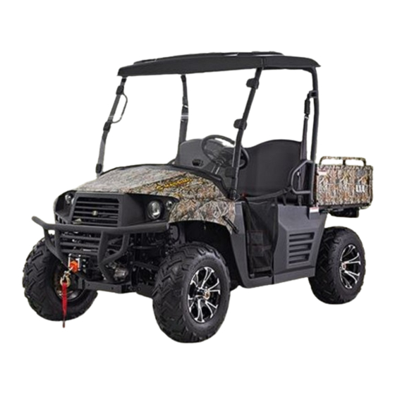
- Page 2 INTRODUCTION Congratulations on your purchase of the Massimo MSU 400 UTV. With the pur- chase of this vehicle, you can now appreciate the high degree of craftsmanship. This manual will provide you with a good basic understanding of the features and operation of this vehicle.
-
Page 4: Important Manual Information
Owner Manual IMPORTANT MANUAL INFORMATION FAILURE TO FOLLOW THE WARNINGS CONTAINED IN THIS MANUAL CAN RESULT IN SERIOUS INJURY Particularly important information is distinguished in this manual by the following OR DEATH. notations: The Safety Alert Symbol means ATTENTION! YOUR SAFETY IS INVOLVED! Failure to follow WARNING instructions could result in severe injury or death to the machine operator, bystander or a person inspecting or repairing the machine. -
Page 5: Important Notice
Owner Manual IMPORTANT NOTICE This UTV is designed and manufactured for OFF - ROAD use only. It is illegal and unsafe to operate this UTV on any public street, road or highway. This UTV complies with all applicable OFF - ROAD noise level and spark arrester laws and regulations in effect at the time of manufacture. -
Page 6: Table Of Contents
Owner Manual Location of the Warning and Throttle Pedal 4-15 Safety Labels Brake Pedal 4-16 Parking brake pedal 4-16 Safety Information Drive Select Lever 4-17 Fuel Tank Cap 4-18 Description and Vehicle Starter 4-18 Identification Seats 4-19 Identification Number Records Seat Belts 4-20 Vehicle Identification Number... - Page 7 Owner Manual Operation Brake Fluid Level Starting a Cold Engine Brake Operation Starting a Warm Engine Fuel Jump Starting Engine Oil Warming Up Coolant Drive Select Lever Operation and Final Gear Oil Reverse Differential Gear Oil Parking Throttle Pedal Parking on a Slope Throttle Freeplay 6-10 Throttle Freeplay Inspection...
- Page 8 Owner Manual Crossing Through Shallow Water 7-12 To Check Engine Oil Level 8-11 Vehicle Immersion 7-14 To Change the Engine Oil (With or Rear Axle Differential Lock 7-15 Without Oil Fliter Cartridge Riding Over Rough Terrain 7-16 Replacement 8-12 Riding in Brush or Wooded Areas 7-17 Checking the Final Gear Oil Level 8-15...
- Page 9 Owner Manual Cleaning the Spark Arrester 8-30 Tail / Brake Light Bulb Valve Clearance 8-32 Replacement 8-49 Front Brake Pad Check 8-32 Troubleshooting 8-50 Common Problems in Vehicle 8-53 Rear Brake Pad Check 8-33 Checking the Brake Fluid Level 8-33 Brake Fluid Replacement 8-35 Cleaning and Storage...
-
Page 10: Location Of The Warning And Safety Labels
Location of the Warning and Safety Labels... - Page 11 Location of the Warning and Safety Labels Read and understand all of the labels on your vehicle. They contain important information for safe and proper operation of your vehicle. Never remove any labels from your vehicle. If a label becomes difficult to read or comes off, a replacement label is available by contacting the dealer.
- Page 12 Location of the Warning and Safety Labels...
- Page 13 Location of the Warning and Safety Labels...
- Page 14 Location of the Warning and Safety Labels...
- Page 15 Safety Information SAFETY INFORMATION This off-highway utility vehicle handles differently from other vehicles including cars and UTVs. SEVERE INJURY OR DEATH can result if you do not follow these instructions: Read this manual and all labels carefully and follow the operating procedures described. ●...
-
Page 16: Safety Information
Safety Information Never attempt jumps or other stunts. ● Always inspect your vehicle each time you use it to be sure it is in safe operating condition, Always ● follow the inspection and maintenance procedures and schedules described in this manual. Always keep hands, arms, feet, and legs inside the vehicle at all times during operation. - Page 17 Safety Information Never operate on hills that are slippery or ones where you will not be able to see far enough ahead of ● you. Never go over the top of a hill at speed if you cannot see what is on other side. Always follow proper procedures for going uphill.
- Page 18 Safety Information WARNING POTENTIAL HAZARD Improper handling of gasoline. WHAT CAN HAPPEN Gasoline can catch fire and you could be burned. HOW TO AVOID THE HAZARD Always turn off the engine when refueling. Do not refuel right after the engine has been running and is still very hot.
- Page 19 Safety Information WARNING POTENTIAL HAZARD Starting or running the engine in a closed area. WHAT CAN HAPPEN Exhaust fumes are poisonous and may cause loss of consciousness and death within a short time. HOW TO AVOID THE HAZARD Always operate your vehicle in an area with adequate ventilation.
-
Page 20: Description And Vehicle Identification
Description and Vehicle Identification Headlights Spark arrester Front shock absorber assembly Rear shock absorber assembly Brake fluid reservoir CVT-belt case Driver seat Fuel tank cap Battery Passenger seat belt Fuses Right body protection plate Left body protection plate Spark plug Driver seat belt Oil filter cartridge Air filter element... - Page 21 Description and Vehicle Identification Parking brake lever Steering wheel Ignition switch Light switch On-Command four-wheel-drive and differential lock switches Multi-function display gauge Auxiliary DC jack Drive select lever Accelerator pedal Brake pedal Release parking handle NOTE: The vehicle you have purchased may differ slightly from those in the figures of this manual.
-
Page 22: Identification Number Records
Description and Vehicle Identification Identification Number Records Vehicle Identification Number Record the Vehicle Identification Number and The Vehicle Identification Number is stamped model label information in spaces provided for into the frame. assistance when ordering spare parts from a service center or for reference in case the vehicle is stolen. -
Page 23: Control Functions
Control Functions CONTROL FUNCTIONS Functions of the respective switch positions are as follows: Ignition Switch All electrical circuits are supplied with power. Headlights and taillights come on when the light switch is turned to the “on” position. OFF: All electrical circuits are switched off. The key can be removed in this position. -
Page 24: Indicator And Warning Lights
Control Functions Indicator and Warning Lights CAUTION: Do not operate the electric starter ● continuously for more than 5 seconds at a time. Wait at least 5 seconds between each start attempt to prevent damage to the starter Do not turn the key to the “START” ●... - Page 25 Control Functions Forward indicator light Light “F” specified level, this light comes on to warn This indicator light comes on when the drive that the coolant temperature is too hot. If select lever is in the “F” position. the light comes on during operation, stop the engine as soon as it is safe to do so and Mechanical Parking Brake Indicator Light allow the engine to cool down for about 15...
-
Page 26: Use Of Eps System
Control Functions take some measures keep Position light indicator The light being on means that the position himself/herself safe. light fixed in the front headlight has been When fault occurs on EPS system, fault turned on. indicator light will be lit up. At the same time, fault indicator of EPS system will display the Emergency indicator“... -
Page 27: Speedometer Unit
Control Functions Speedometer Unit then you should consult your local dealer for maintenance in time. Oil Overheat Indicator The light will turn on when the UTV is overheating NOTE: If the engine is overheating, stop the UTV immediately. Do not start the engine again until the UTV has been inspected and 1. -
Page 28: Odometer And Trip Meter Modes
Control Functions Speedometer unit functions: from the odometer, to the tripometer, and a speedometer (which shows the speed) then to the hours meter; then it starts the an odometer (which shows the total cycle over. distance covered) The odometer displays the total distance a tripometer (which can be cleared and traveled by the UTV. - Page 29 Control Functions button on the display. This will also change panel. The left 4WD indicator has a blinking displayed mileage from miles circle on the front axle when the grey and kilometers. yellow 4WD selector buttons are pressed in indicating the “4WD” function has been Clock time adjustment activated.
-
Page 30: Fault Code Indicator
Control Functions slippery roads or when climbing a steep hill, symbols showing in either the left or right make sure the 4WD lock indicator is on. 4WD indicators. When riding on a flat road at a comparatively high speed, adjust settings CAUTION: “2WD/UNLOCK”... - Page 31 Control Functions time press the clock button, the time will be shown. Then after five seconds, the fault code returns again. Only after the fault is fixed, will the time show automatically. The description for the fault codes are shown in Chapter 11 of this manual.
-
Page 32: Switches
Control Functions 4-10 Switches CAUTION: Do not use the headlights with the engine turned off for an extended period. The battery may discharge to the point that the starter motor will not operate properly. If this should happen, remove the battery and recharge it. 1. -
Page 33: On-Command Four-Wheel-Drive And Differential Gear Lock Switches
4-11 Control Functions On-Command Four-Wheel–Drive and Two-wheel drive (”2WD”): Power is sup- Differential Gear Lock Switches plied to the rear wheels only. Four-wheel drive (“4WD”): Power is supplied to the rear and front wheels. Four–wheel drive with the differential gear locked (“4WD-LOCK”): Power is supplied to the rear and front wheels when the differential gear is locked. - Page 34 Control Functions 4-12 On-Command Four-Wheel-Drive Switch WARNING “2WD/4WD” POTENTIAL HAZARD Changing from 2WD to 4WD or from 2WD to 2WD-Differential UNLOCK, or vice-versa while the vehicle is moving. WHAT CAN HAPPEN The vehicle handles differently in 4WD than in 2WD and in 2WD- Differential UNLOCK in some circumstances.
- Page 35 4-13 Control Functions To change from 4WD to 2WD Stop the vehicle, and then set the switch to “2WD”。The 4WD indicator will go out in the multi-function display. On-Command Differential Gear Lock Switch “2WD/LOCK” To lock the differential gear in 4WD, stop the vehicle, make sure the On-Command four-wheel-drive switch is set to “4WD”, On-Command differential lock switch “4WD/LOCK”...
- Page 36 Control Functions 4-14 NOTE: WARNING When the switch is set to “LOCK”, the POTENTIAL HAZARD differential gear lock indicator and Riding too fast while the vehicle is in indicator lights will flash until the 4WD-LOCK. differential gear is locked. WHAT CAN HAPPEN When the differential gear lock indicator All wheels turn at the same speed when and indicator lights are flashing, turning...
-
Page 37: Throttle Pedal
4-15 Control Functions Before starting the engine, check the throttle Throttle Pedal pedal to be sure it is operating smoothly. Press the throttle pedal down to increase Make sure the throttle pedal fully returns to engine speed. Spring pressure returns the the idle position as soon as it is released. -
Page 38: Brake Pedal
Control Functions 4-16 Brake Pedal WARNING Press the brake pedal to slow or stop the POTENTIAL HAZARD vehicle. Malfunction of the throttle or pedal. WHAT CAN HAPPEN The accelerator pedal could be hard to operate, making it difficult to speed up or slow down when you need to. -
Page 39: Drive Select Lever
4-17 Control Functions vehicle from moving while parked. To set the parking brake, depress the parking brake pedal completely. To release the parking brake, Pull down the parking brake release handle and depress the parking pedal simultaneously; Release the handle and lift foot off the parking brake gradually. -
Page 40: Fuel Tank Cap
Control Functions 4-18 1. Drive select lever 1. Fuel tank cap Fuel Tank Cap Starter (choke) “ ” Starting a cold engine requires a richer Remove the fuel tank cap by turning it air-fuel mixture. A separate choke cable counter clockwise. supplies this mixture. -
Page 41: Seats
4-19 Control Functions operation. (See pages 6-1 - 6-3.) A. Choke knob 1. Fully open 1. Driver / Passenger seat To install seat bench, insert tabs on rear of 2. Half open 3. Closed seat into the seat holders located on the UTV frame. -
Page 42: Seat Belts
Control Functions 4-20 Seat belts This vehicle is equipped with three-point seat WARNING belts for both the operator and passenger. POTENTIAL HAZARD A loose seat. Always wear seat belts while riding in the WHAT CAN HAPPEN vehicle. The operator could lose control or the operator and/or passenger could fall if the seat is loose during operation. - Page 43 4-21 Control Functions Proper use of the seat belts involves the following steps: 1. Hold the latch plate as you pull the belt across your lap and chest. Make sure the belt is not twisted and is not caught on any portion of the vehicle, your clothing, or any equipment you are carrying.
- Page 44 Control Functions 4-22 WARNING POTENTIAL HAZARD Not wearing the seat belt or wearing the seat belt improperly. WHAT CAN HAPPEN There is an increased risk of being killed or seriously injured in an accident. HOW TO AVOID THE HAZARD 1. Buckle 2.
-
Page 45: Glove Compartment
4-23 Control Functions Glove Compartment CAUTION: To prevent damage to the glove compartment do not place metal products, like tools or sharply edged products directly in the glove compartment. If they must be stored, wrap them in appropriate cushion material. . -
Page 46: Cargo Bed
Control Functions 4-24 Cargo Bed Opening and Closing the Tailgate 1. Cargo bed 2. Tailgate 1. Tailgate 2. Latch (×2) To open Unhook latches, and lower the tailgate. To close Place tailgate in original up position, then hook latches. -
Page 47: Lifting And Lowering The Cargo Bed
4-25 Control Functions Lifting and Lowering the Cargo Bed WARNING POTENTIAL HAZARD Pinch points. WHAT CAN HAPPEN You or someone else could be pinched between the cargo bed and the frame when the bed is being lowered. HOW TO AVOID THE HAZARD 1. - Page 48 Control Functions 4-26 WARNING WARNING POTENTIAL HAZARD POTENTIAL HAZARD Overloading the cargo bed. Carrying a passenger in the cargo bed. WHAT CAN HAPPEN WHAT CAN HAPPEN Could cause changes in vehicle handling The passenger could fall, be thrown out, which could lead to an accident. or be struck by objects in the cargo bed.
-
Page 49: Front And Rear Shock Adjustment
4-27 Control Functions Front and Rear Shock Adjustment(Option 1) The spring preload can be adjusted to suit the operating conditions. You can reduce preload for a softer ride, or increase preload if the vehicle is bottoming out on rough terrain. CAUTION: Frequent or severe bottoming out can cause increased wear or damage to the vehicle. - Page 50 Control Functions 4-28 Standard position: B WARNING A-Minimum(soft) POTENTIAL HAZARD E-Maximum(hard) Improper shock absorber adjustment. WHAT CAN HAPPEN Uneven adjustment can cause poor handling and loss of stability, which could lead to an accident. HOW TO AVOID THE HAZARD Always adjust the shock absorbers on the left and right side to the same setting.
- Page 51 4-29 Control Functions Front and Rear Shock Adjustment(Option 2) WARNING ·Do not dispose of a damaged or worn out shock absorber assembly yourself. These shock absorber assemblies Take the shock absorber assembly to a contain highly pressurized nitrogen gas, HSUN dealer for any service. read understand following...
- Page 52 Control Functions 4-30 Spring preload · A special wrench can be obtained at a 1. Loosen the locknut. HSUN dealer to make this adjustment. 2. Turn the spring preload adjusting nut in · The spring preload setting is determined direction ⓐ to increase the spring by measuring distance A, shown in the preload thereby...
- Page 53 4-31 Control Functions damping, and in direction F to decrease the Spring travel setting(Front) rebound damping force and thereby soften Minimum(soft): 375mm(14.76 in) the damping. Maximum(hard): 490mm(19.29 in) Spring travel setting(Rear) Minimum(soft): 402mm(15.83 in) Maximum(hard): 490mm(19.29 in) 3. Tighten the locknut. NOTE: Always tighten the locknut against the adjusting nut, and then tighten it to the...
- Page 54 Control Functions 4-32 Compression damping force Turn compression damping force WARNING adjusting screw (use 2.5 allen wrench) in ·Suspension components become hot direction ⓐ to increase the compression during operation. Never touch damping force and thereby harden the compression damping force adjusting damping, and in direction ⓑ...
-
Page 55: Trailer Hitch Bracket
4-33 Control Functions Auxiliary DC Jack Trailer Hitch Bracket The auxiliary DC jack is located at the right This vehicle is equipped with a 1 1/4 inch side of the front panel. receiver bracket for a standard trailer hitch. The auxiliary DC jack can be used for Trailer towing equipment can be obtained at suitable work lights, radios, etc. - Page 56 Control Functions 4-34 1. Set the light switch to “OFF”. 2. Start the engine. (See pages 6-1-6-3.) Maximum rated capacity for the auxiliary 3. Open the auxiliary DC jack cap, and then DC jack: insert the accessory power plug into the DC 12V, 120W (10 A) jack.
- Page 57 Pre Operation Checks Before using this vehicle, check the following items: ITEM ROUTINE PAGE Check operation, free play, fluid level and fluid leakage ● Brakes 5-2 - 5-3,8-33 - 8-36 Fill with DOT 4 brake fluid if necessary ● Check for proper operation, condition and free play Parking brake ●...
-
Page 58: Pre-Operation Checks
Pre Operation Checks WARNING Brakes Always check the brake pedal travel and the POTENTIAL HAZARD brake fluid reservoir level before each use of Failure to inspect the vehicle before the vehicle. When applied, the brake pedal operating. Failure to properly maintain the should feel firm. -
Page 59: Brake Fluid Level
Pre Operation Checks 8-36.) fluid reservoir. Apply the brakes firmly for one Check operation of the brake pedal. Brake minute. If there is any leakage, have the vehicle pedal should move smoothly and should feel inspected by a service center. firm when the brakes are applied. -
Page 60: Fuel
Pre Operation Checks WARNING Fuel Make sure there is sufficient gasoline in the POTENTIAL HAZARD tank. Driving with improperly operating brakes. WHAT CAN HAPPEN Recommended fuel: You could lose braking ability, which could Unleaded gasoline only lead to an accident. Fuel tank capacity: HOW TO AVOID THE HAZARD 6.86 gal (26 L ) - Page 61 Pre Operation Checks Your engine has been designed to use regular unleaded gasoline with a pump octane number WARNING ([R+M] /2) of 91 or higher, or research octane POTENTIAL HAZARD number of 91 or higher. If knocking or pinging Improper care when refueling. occurs, use a different brand of gasoline or WHAT CAN HAPPEN premium unleaded fuel.
-
Page 62: Engine Oil
Pre Operation Checks Engine Oil Coolant Make sure the engine oil is at the specified level. Check the coolant level in the coolant reservoir when the engine is cold. (The coolant level will Add oil as necessary. (See pages 8-11—8-15.) vary with engine temperature.) The coolant level is satisfactory if it is between the minimum CAUTION:... -
Page 63: Final Gear Oil
Pre Operation Checks Final Gear Oil Coolant reservoir capacity Make sure the final gear oil is at the specified (up to the maximum level mark): level. Add oil as necessary. (See pages 8-18 - 0.627L(0.555lmp qt, 0.663US qt) 8-19 for details.) Recommended oil: WARNING SAE 80 API GL-4 Hypoid gear oil... -
Page 64: Throttle Pedal
Pre Operation Checks Recommended oil: WARNING SAE 80 API GL-5 Hypoid gear oil Failure to check or maintain proper operation of the throttle system can result in an accident Throttle Pedal leading to serious injuries or death. Check to see that the Throttle pedal operates Never start or operate this vehicle if it has a correctly. -
Page 65: Throttle Freeplay
Pre Operation Checks Throttle Freeplay Throttle Freeplay Adjustment If the throttle pedal has excessive play due to 1. Remove seat. cable stretch or mis-adjustment, it will cause a 2. Loosen the throttle cable column nut. Adjust the throttle cable so the throttle pedal delay in throttle response, especially at low freeplay is 1/16 to 1/8 inches (1.5-3mm). -
Page 66: Steering Wheel Inspection
Pre Operation Checks 5-10 Steering Wheel Inspection and release when the release button is pushed Check the steering wheel for specified freeplay firmly. Wash off any dirt or mud which could and smooth operation。 affect operation. Have a service center repair as 1. - Page 67 5-11 Pre Operation Checks WARNING POTENTIAL HAZARD Operating this vehicle with improper tires, or with improper or uneven tire pressure. WHAT CAN HAPPEN Use of improper tires on this vehicle, or operation of this vehicle with improper or uneven tire pressure, may cause loss of control, increasing your risk of accident.
- Page 68 Pre Operation Checks 5-12 3. Tire pressure below the minimum specified could cause the tire to dislodge from the rim under severe riding conditions. The following are minimums: Front 9psi (63kpa 0.64kgf/cm Rear 9psi (63kpa 0.64kgf/cm 4. Use no more than the following Pressures when seating the tire beads.
- Page 69 5-13 Pre Operation Checks How to measure tire pressure Use the tire pressure gauge. NOTE: The tire pressure gauge is included as standard equipment. Make two measurements of the tire pressure and use the second reading. Dust or dirt in the gauge could cause the first reading to be incorrect.
-
Page 70: Tire Wear Limit
Pre Operation Checks 5-14 Tire Wear Limit When the tire groove decreases to 0.12 in (3 mm) due to wear, replace the tire a. Tire wear limit... -
Page 71: Operation
Operation Starting a cold engine WARNING WARNING POTENTIAL HAZARD POTENTIAL HAZARD Operating vehicle without being familiar Freezing control cables in cold weather. with all controls. WHAT CAN HAPPEN WHAT CAN HAPPEN You could be unable to control the Loss of control, which could cause an vehicle, which could lead to an accident accident or injury. - Page 72 Operation NOTE: When the drive select lever is in the Position③: Cold engine start ambient ● neutral position, the neutral indicator temperature above 86°F (30℃) light should come on. If the neutral indicator light does not come on, ask a service center to inspect the electric circuit.
-
Page 73: Starting A Warm Engine
Operation Starting a warm engine NOTE: If the engine fails to start, release the key, To start a warm engine, refer to the“Starting and then try starting again. Wait a few a cold engine” section. The choke should not seconds before the next attempt. Each be used. - Page 74 Operation NOTE: Do not connect the negative lead of the jumper cable to the negative terminal of the battery in the vehicle. Be especially careful not to: ● touch the positive lead of the jumper cable to the negative lead. ●...
-
Page 75: Warming Up
Operation 9. Close the hood. accelerator pedal. Warming up To get maximum engine life, always warm up Apply the brakes, and then shift by the engine before starting off. Never moving the drive select lever along the accelerate hard with a cold engine! To see shift guide. - Page 76 Operation 3. Release the brakes and press the accelerator pedal gradually. Shifting: Neutral to Reverse 1. Stop the vehicle. Keep your foot off the accelerator pedal. 2. Depress the brake pedal. 3. Shift from neutral to reverse or vice versa by moving the drive select lever along the shift guide.
- Page 77 Operation 4. Check behind for people or obstacles, Vehicle Break-in Period and then release the brake pedal. The break-in period for your new UTV 5. Press the accelerator pedal gradually vehicle is the first 25 hours of operation, or and continue to watch to the rear while the time it takes to use the first three tanks backing.
- Page 78 Operation Use of any engine oil not recommended maximum) full throttle operation under load ● in this manual will cause severe damage does not harm the engine. to the engine。 Each full throttle acceleration sequence should be followed with a substantial rest Engine Break-In period for the engine by cruising at lower rpm’s so the engine can rid itself of the...
-
Page 79: Parking
Operation throttle at any time. period. After Break-In: The vehicle can now be operated normally. Parking When parking, stop the engine and shift the Brake System Break-in drive select lever into the neutral position. Apply only moderate braking force for the Apply the parking brake to help prevent the first 50 stops. -
Page 80: Parking On A Slope
Operation 6-10 Parking on a slope WARNING POTENTIAL HAZARD Parking on a hill or other incline. WHAT CAN HAPPEN The vehicle could roll out of control, increasing the chance of an accident. HOW TO AVOID THE HAZARD Avoid parking on hills or other inclines. If 1. - Page 81 6-11 Operation Accessories can shift position or come off while you Accessories can affect the handing and are operating could affect your ability to control of your vehicle. Keep the following in control the vehicle. mind when considering an accessory or Do not mount an accessory where it ●...
- Page 82 Operation 6-12 judgment when carrying cargo or towing a Do not exceed the maximum tongue ● trailer. Keep the following points in mind: weight. You can measure tongue weight Never exceed the weight limits shown. with a bathroom scale. Put the tongue of ●...
- Page 83 6-13 Operation with controls or your ability to see where you are going. WARNING Drive slower than you would without a POTENTIAL HAZARD ● load. The more weight you carry, the Overloading this vehicle or carrying or slower you should go. Although towing cargo improperly.
-
Page 84: Your Vehicle
Your Vehicle DRIVING YOUR VEHICLE WARNING GETTING TO KNOW YOUR VEHICLE POTENTIAL HAZARD This off-highway utility vehicle will handle Not wearing the seat belt. and maneuver differently form an ordinary Wearing the seat belt improperly. passenger car or other vehicle. WHAT CAN HAPPEN Before you begin to use your vehicle, be sure There is increased risk of being killed or... - Page 85 Your Vehicle The total weight of operator, passenger, WARNING accessories, cargo, trailer tongue weight, and the vehicle itself must not exceed POTENTIAL HAZARD 1880lbs (853Kg). Carrying a passenger in the cargo bed. WHAT CAN HAPPEN The passenger could fall or be struck by objects in the cargo bed.
- Page 86 Your Vehicle The driver and passenger must always wear WARNING a seat belt, an approved motorcycle helmet, eye protection and protective clothing, POTENTIAL HAZARD Overloading this vehicle or carrying or including over-the-ankle boots, gloves, a towing cargo improperly. long-sleeved shirt or jacket, and long pants. WHAT CAN HAPPEN Keep hands and feet inside the vehicle at all Could cause changes in vehicle handling...
- Page 87 Your Vehicle WARNING HOW TO AVOID THE HAZARD POTENTIAL HAZARD Always wear an approved motorcycle Operating this vehicle without wearing an helmet that fits properly. You should also approved motorcycle helmet, eye wear: protection, and protective clothing. Eye Protection WHAT CAN HAPPEN (Goggles or Face Shield) Operating without...
-
Page 88: Learning To Operate Your Vehicle
Your Vehicle LEARNING TO OPERATE YOUR VEHICLE neutral, and follow the instructions on page You should become familiar with the 6-1 to start the engine. Once it has warmed performance characteristics of the vehicle in up and you have turned the choke off, you a large, flat area that is free of obstacles and are ready to begin driving your vehicle. -
Page 89: Turning Your Vehicle
Your Vehicle CAUTION: Position your hands on the steering wheel so Do not shift from low to high or vice versa that your thumbs and fingers do not wrap without coming to a complete stop and around the wheel. This is particularly waiting for the engine to return to normal idle important when driving in rough terrain. -
Page 90: Operating Improperly In Reverse
Your Vehicle Follow these precautions when operating in reverse: 1. Always check for obstacles or people behind the vehicle. 2. Apply the throttle lightly. Never open the throttle suddenly. 3. Back up slowly. 4. Apply the brakes lightly for stopping. Operating Improperly in Reverse 5. -
Page 91: Braking
Your Vehicle BRAKING Braking ability is affected by the type of terrain. In most cases, gradually application of the brakes is more effective than abrupt braking, particularly on loose surfaces like gravel. Always allow for greater braking distance on rough, loose, or slippery surfaces. - Page 92 Your Vehicle some hills are too steep for you to climb. Choose carefully which hills you attempt to Maximum slope angle: 15° climb. Avoid hills with slippery surfaces or ones where you will not be able to see far enough ahead of you.
- Page 93 7-10 Your Vehicle Before climbing the hill, first be sure you are WARNING operating in low range 4WD or, if necessary, POTENTIAL HAZARD with 4WD Diff. Lock. To climb a hill, you need Operating on excessively steep hills. traction, momentum, and steady throttle. WHAT CAN HAPPEN Travel fast enough to keep your momentum The vehicle can over turn more easily on...
-
Page 94: Going Downhill
Your Vehicle 7-11 behind you and plan your descent. Shift the drive select lever in reverse so you can use WARNING the engine brake if necessary to slow your POTENTIAL HAZARD descent. Release the brake and begin to Going down a hill improperly. coast down the hill. -
Page 95: Crossing Through Shallow Water
7-12 Your Vehicle Before starting downhill, make sure the CROSSING THROUGH SHALLOW WATER vehicle is in low-range 4WD. On most slopes, If you must cross shallow, slow moving water this will let you use engine braking to help up to the depth of the vehicle’s floorboards, you go downhill slowly. - Page 96 Your Vehicle 7-13 CAUTION: WARNING After riding your vehicle in water, be sure to POTENTIAL HAZARD Operating this vehicle through deep or drain the trapped water by removing the fast-flowing water. check hose at the bottom of the air filter case, WHAT CAN HAPPEN the CVT-belt cooling duct check hose, the Loss of control, which could result in an...
-
Page 97: Vehicle Immersion
7-14 Your Vehicle Vehicle Immersion 5. Dry the spark plugs and reinstall them, or install new plugs. CAUTION: 6. Attempt to start the engine. If necessary, If your vehicle becomes immersed, major repeat the drying procedure. engine damage can result if the machine is 7. - Page 98 Your Vehicle 7-15 CAUTION: Make sure all components that are washed and assembled are coated lightly with grease. 1.CVT Gear Box inspection hole Front Axle Differential Lock When driving on rugged or muddy roads, locking the differential case in the front axle gearbox will give you the best traction.
-
Page 99: Riding Over Rough Terrain
7-16 Your Vehicle destroyed the soil structure. Even if you lock WARNING the differential, the front wheels may POTENTIAL HAZARD continue to slip and will not drive the vehicle Failure to use extra care when operating ahead. this vehicle on unfamiliar terrain. WHAT CAN HAPPEN Riding Over Rough Terrain You can come upon hidden rocks,... -
Page 100: Riding In Brush Or Wooded Areas
Your Vehicle 7-17 Riding in Brush or Wooded Areas When operating in areas with brush or trees, watch carefully on both sides and above the vehicle for obstacles such as branches that the vehicle might hit, causing an accident, or for brush that might enter the vehicle as you pass and strike the driver or passenger. -
Page 101: Encountering Obstacles On The Trail
7-18 Your Vehicle Encountering Obstacles on the Trail WARNING If you cannot go around an obstacle such as a fallen tree trunk or a ditch, stop the vehicle POTENTIAL HAZARD where it is safe to do so. Set the parking Improperly operating over obstacles. -
Page 102: Periodic Maintenance And Adjustment
Periodic Maintenance and Adjustment Periodic inspection, adjustment and NOTE: lubrication will keep your vehicle in the safest If you do not have a torque wrench available and most efficient condition possible. Safety during a service operation requiring one, take is an obligation of the vehicle owner. The your vehicle to a service center to check the most important points of vehicle inspection, torque settings and adjust them as... - Page 103 Periodic Maintenance and Adjustment WARNING WARNING POTENTIAL HAZARD POTENTIAL HAZARD Operating this vehicle with improper Servicing an engine while it is running. modifications. WHAT CAN HAPPEN WHAT CAN HAPPEN Moving parts can catch clothing or parts Improper installation of accessories or of the body, causing injury.
-
Page 104: Periodic Maintenance Chart For The Emission Control System
Periodic Maintenance and Adjustment Periodic Maintenance Chart for the Emission Control System ● For vehicles not equipped with an odometer or hour meter, follow the month maintenance intervals. ● For vehicles equipped with an odometer or an hour meter, follow the km (mi) or hours maintenance intervals. However, keep in mind that if the vehicle is not used for a long period, the month maintenance intervals should be followed. -
Page 105: General Maintenance And Lubrication Chart
Periodic Maintenance and Adjustment General Maintenance and Lubrication Chart INITIAL EVERY Month Whichever ITEM ROUTINE Miles 1,200 2,400 2,400 4,800 Comes first (Km) (200) (750) (1,500) (1,500) (3,000) hours ● Check operation/brake pad wear/fluid leakage/see Rear Brake* NOTE page 5-2-5-3. ○... - Page 106 Periodic Maintenance and Adjustment INITIAL EVERY Month Whichever ITEM ROUTINE Miles 1,200 2,400 2,400 4,800 Comes first (Km) (200) (750) (1,500) (1,500) (3,000) hours ● Check for cracks or damage. Engine Mount* ○ ○ ○ ● Check bolt tightness. ● Check operation and for looseness. Replace if Steering System* damaged.
-
Page 107: Hood
Periodic Maintenance and Adjustment Hood To Open Unhook the hood latches, and then slowly tilt the hood up until it stops. 1. Hood 1. Latch (×2) -
Page 108: To Close
Periodic Maintenance and Adjustment To Close CAUTION: Lower the hood slowly to its original position, Make sure that all cables and wires are in and then hook the hood latches. place when closing the hood. Secure projections on the underside of the Do not drive the vehicle with the hood hood into slots on the back of the instrument open, unlatched, or removed. -
Page 109: Efi System
Periodic Maintenance and Adjustment EFI system EFI engine was completely different from the engine which uses carburetor, it consist of ECU, EFI-cables, sensors, actuators and other advanced components. As the following pictures: 1. ECU 1. Oxygen sensor 2. Oxygen sensor threaded sleeve 3. - Page 110 Periodic Maintenance and Adjustment 1. High voltage wire 2.Ignition signal plug 3. Ignition coil 2. Water temperature sensor 1. Fuel injector 2. Bent pipe, inlet pipe 3. Intake air temperature sensor/ pressure sensor 4. Ducting dampers 1. Air damper degree sensor 2.
- Page 111 8-10 Periodic Maintenance and Adjustment Air damper different negative pressure and opening of For the purpose of adjustment of air intake air damper. Adjust the engine fuel injection volume. volume can adjust the output power and output torque. Idle speed stepper motor To stabilize the idle speed Water temperature sensor For testing cooling water temperature,...
-
Page 112: Efi System Inspection
Periodic Maintenance and Adjustment 8-11 Engine Oil and Oil Filter Cartridge achieve fuel-efficient emissions performance of the EFI engine. The engine oil level should be checked before each operation. In addition, the oil must be changed and the oil filter cartridge EFI System inspection replaced at the intervals specified in the If the EFI system has failure, the meter will... -
Page 113: To Change The Engine Oil
8-12 Periodic Maintenance and Adjustment NOTE: and then tighten the oil filler cap. The engine oil should be between the 8. Install the console. minimum and maximum level marks. To Change the Engine Oil (With or Without Oil Filter Cartridge Replacement) 1. - Page 114 Periodic Maintenance and Adjustment 8-13 1. Engine oil drain bolt 1. Oil filter cartridge 2. Oil filter bolt NOTE: NOTE: Skip steps 4-6 if the oil filter cartridge is not An oil filter wrench is available at a nearby being replaced. service center.
- Page 115 8-14 Periodic Maintenance and Adjustment 1. Oil filler cartridge 2. Torque bolt O-ring 7. Install the engine oil drain bolt, and then 6. Install the new oil filter cartridge with an tighten it to the specified torque. oil filter wrench, and then tighten it to the Tightening torque: specified torque with a torque wrench.
-
Page 116: Checking The Final Gear Oil Level
Periodic Maintenance and Adjustment 8-15 9. Start the engine, and then let it idle for Recommended engine oil: several minutes while checking it for oil See page 10-2. leakage. If oil is leaking, immediately turn Oil quantity: the engine off and check for the cause. Without oil filter cartridge replacement: 10. -
Page 117: Changing The Final Gear Oil
8-16 Periodic Maintenance and Adjustment CAUTION: Be sure no foreign material enters the final gear case. 4. Install the oil filler bolt, and then tighten it to the specified torque. Tightening torque: 1. Speed meter sensor 2. Final gear oil Final gear oil filler bolt: 3. - Page 118 Periodic Maintenance and Adjustment 8-17 the brim of the filler hole. Recommended oil: SAE 80 API GL-4Hypoid gear oil Oil quantity: 0.42 qt (0.4 L) CAUTION: 1. Final gear oil drain bolt Be sure no foreign material enters the final 4.
-
Page 119: Differential Gear Oil
8-18 Periodic Maintenance and Adjustment Tightening torque: Final gear oil filler bolt: 16.3 ft·lbs (23 Nm, 2.3 m·kgf) 7. Check for oil leakage. If oil leakage is found, check for the cause. Differential Gear Oil Checking the Differential Gear Oil Level 1. -
Page 120: Changing The Differential Gear Oil
Periodic Maintenance and Adjustment 8-19 2. Install the differential gear oil filler bolt, and then tighten it to the specified torque. Tightening torque: Differential gear oil filler bolt: 16.3 ft·lbs (23Nm, 2.3 m·kgf) Changing the Differential Gear Oil 1. Place the vehicle on a level surface. 2. -
Page 121: Oil Cooler
8-20 Periodic Maintenance and Adjustment and then tighten it to the specified torque. Tightening torque: Tightening torque: Differential gear oil drain bolt: Differential gear oil filler bolt: 16.3 ft·lbs (23Nm, 2.3m·kgf) 16.3 ft·lbs (23Nm, 2.3m·kgf) 7. Check for oil leakage. If oil leakage is found, check for the cause. -
Page 122: Coolant
Periodic Maintenance and Adjustment 8-21 Coolant Before each use of the UTV, check and The coolant level should be checked before remove the sand, leaves and other foreign each ride. objects from the gap between the protection net and oil cooler. Then wash the sand from Checking the Coolant Level the air flowing gap in the oil cooler, ensure 1. -
Page 123: Changing The Coolant
8-22 Periodic Maintenance and Adjustment Coolant reservoir capacity (up to the maximum level mark): 0.663 qt (0.627L) CAUTION: Mix anti freeze with distilled water only. However, if distilled water is not available, soft water can be used for refilling. Changing the Coolant Coolant reservoir cap The coolant must be changed by a service Maximum level mark... -
Page 124: Axle Boots
Periodic Maintenance and Adjustment 8-23 Axle Boots Total amount: Check the protective boots for holes or tears. 1.40 qt (1.32L) If any damage is found, have them replaced Coolant reservoir capacity by a service center. (up to the maximum level mark): 0.65 qt (0.627 L) NOTE: Adding water instead of coolant lowers... -
Page 125: Spark Plug Inspection
8-24 Periodic Maintenance and Adjustment Spark plug cap 1. Rear axle boot (×2 each side) Spark Plug Inspection Removal Remove hood (See pages 8-6) 2. Remove the spark plug cap. 3. Use the spark plug wrench in the tool kit to remove the spark plug as shown. -
Page 126: Inspection
Periodic Maintenance and Adjustment 8-25 Inspection The spark plug is an important engine Specified spark plug: component and is easy to inspect. The DR8EA (NGK) condition of the spark plug can indicate the condition of the engine. Installation The ideal color of the porcelain insulator 1. - Page 127 8-26 Periodic Maintenance and Adjustment NOTE: If a torque wrench is not available when you Spark plug gap: are installing the spark plug, a good estimate 0.023-0.027 in (0.6-0.7mm) of the correct torque is 1/4 to 1/2 turn past finger tight. Have the spark plug tightened to 2.
- Page 128 Periodic Maintenance and Adjustment 8-27 then remove the air cleaner. 1. Holder (×3) 2. Air filter case cover Air filter check hose 1. Remove the seats. (See pages 4-19 - 4-20 for seat removal and installation 4. Remove the air filter element. procedure.) 5.
- Page 129 8-28 Periodic Maintenance and Adjustment 3. Element retaining plate 6. Wash the sponge material gently but thoroughly in solvent. WARNING POTENTIAL HAZARD Using low flash point solvents or gasoline to clean the sponge material. 1. Air filter element WHAT CAN HAPPEN Low flash point solvents or gasoline can catch fire or explode.
- Page 130 Periodic Maintenance and Adjustment 8-29 CAUTION: Do not twist the sponge material when squeezing it. 8. Inspect the sponge material and replace it if damaged. 9. Thoroughly apply foam air filter oil or other quality liquid foam air filter oil (not spray type) to the sponge material.
-
Page 131: Cleaning The Spark Arrester
8-30 Periodic Maintenance and Adjustment air filter element maintenance is performed, Cleaning the Spark Arrester check the air inlet to the air filter case for Be sure the exhaust pipe and muffler are obstructions. Check the air filter element cool before cleaning the spark arrester. rubber joint to the throttle valve and manifold 1. - Page 132 Periodic Maintenance and Adjustment 8-31 tailpipe and inside of the tailpipe housing. 8.5 ft·lbs (12 Nm, 1.2 m·kgf) WARNING POTENTIAL HAZARD Improper cleaning of the spark arrester. Hot exhaust system. WHAT CAN HAPPEN Could injure the eyes. Could cause burns. Could cause carbon monoxide 1.
-
Page 133: Valve Clearance
8-32 Periodic Maintenance and Adjustment Valve Clearance The correct valve clearance changes with use, resulting in improper fuel-air supply or engine noise. To prevent this, the valve clearance must be adjusted regularly. This adjustment however, should be left to a professional service technician. -
Page 134: Rear Brake Pad Check
Periodic Maintenance and Adjustment 8-33 Rear brake pad check Each brake pad is provided with wear indicator grooves, which allow you to check the brake pad wear without having to disassemble the brake system. To check the brake pad wear, check the wear indicator grooves. - Page 135 8-34 Periodic Maintenance and Adjustment indicate worn brake pads and/or brake the top of the brake fluid reservoir is system leakage. If the brake fluid level is low, level. be sure to check the brake pads for wear and Use only the recommended quality brake the brake system for leakage.
-
Page 136: Brake Fluid Replacement
Periodic Maintenance and Adjustment 8-35 Brake Fluid Replacement Complete fluid replacement should be done only by trained service personnel. Have a service center replace the following components during periodic maintenance or when they are damaged or leaking. Replace the oil seals every two years. Replace the brake hoses every four years. -
Page 137: Brake Light Switch Adjustment
8-36 Periodic Maintenance and Adjustment Brake Light Switch Adjustment WARNING The brake light switch, which is activated by POTENTIAL HAZARD the brake pedal, is properly adjusted when Operating with improperly serviced or the brake light comes on just before braking adjusted brakes. -
Page 138: Cable Inspection And Lubrication
Periodic Maintenance and Adjustment 8-37 Cable Inspection and Lubrication WARNING POTENTIAL HAZARD Damaged control cables. WHAT CAN HAPPEN Corrosion can result when the outer covering of control cables becomes damaged. Cables can also become frayed 1. Brake light switch. 2. Adjusting nut or kinked. -
Page 139: Brake Pedal And Accelerator Pedal Lubrication
8-38 Periodic Maintenance and Adjustment Brake Pedal and Accelerator Pedal Lubricate the inner cables and the cable Lubrication ends. If the cables do not operate smoothly, Lubricate the pivoting parts. ask a service center to replace them. Recommended lubricant: Recommended lubricant: Lithium-based grease Engine oil:see page 10-2 (all-purpose grease) -
Page 140: Rear Knuckle Upper And Lower Pivot Lubrication
Periodic Maintenance and Adjustment 8-39 Rear Knuckle Upper and Lower Pivot Steering Shaft Lubrication Lubrication Lubricate the pivot points. Lubricate the knuckle upper and lower pivots Recommended lubricant: with a grease gun. Lithium-based grease (all-purpose grease) Upper universal joint, steering transmission shaft Recommended lubricant: Lithium-based grease... - Page 141 8-40 Periodic Maintenance and Adjustment Front balance rod Lower universal joint, steering transmission shaft...
-
Page 142: Wheel Installation
Periodic Maintenance and Adjustment 8-41 Rear balance rod Wheel Installation 1. Install the wheel and the nuts. NOTE: The arrow mark on the tire must point ● toward the rotating direction of the wheel. Tapered nuts are used for both the front ●... -
Page 143: Battery
8-42 Periodic Maintenance and Adjustment Battery This vehicle is equipped with a sealed-type battery. Therefore, it is not necessary to check the electrolyte or add distilled water in the battery. If the battery seems to have discharged, consult a service center. CAUTION: Do not try to remove the sealing caps of the 1. - Page 144 Periodic Maintenance and Adjustment 8-43 WARNING POTENTIAL HAZARD Failure to handle batteries or battery electrolyte carefully. WHAT CAN HAPPEN You could be poisoned. You could be severely burned by the sulfuric acid in battery electrolyte. Batteries produce explosive gases. HOW TO AVOID THE HAZARD Avoid contact with skin, eyes or clothing.
-
Page 145: Battery Maintenance
8-44 Periodic Maintenance and Adjustment Battery Maintenance CAUTION: A special battery charger (constant 1. When the vehicle is not used for a month voltage/ampere or constant voltage) is or longer, remove the battery and store it required for recharging a sealed-type battery. in a cool, dark place. - Page 146 Periodic Maintenance and Adjustment 8-45 WARNING POTENTIAL HAZARD Using an improper fuse WHAT CAN HAPPEN An improper fuse can cause damage to the electrical system, which could lead to a fire. HOW TO AVOID THE HAZARD Always use a fuse of the specified rating. Never use a material in place of the proper fuse.
- Page 147 8-46 Periodic Maintenance and Adjustment Specified Fuse: Main Fuse: 30.0A Headlight Fuse: 15.0A Ignition Fuse: 10.0A Auxiliary DC Jack Fuse: 10.0A Signaling System Fuse: 10.0A Carburetor Warmer Fuse: 10.0A 2WD/4WD Fuse 3.0A Backup Fuse: 10.0A 1. Main fuse 2. Spare main fuse 4.
-
Page 148: Replacing Headlight Bulb
Periodic Maintenance and Adjustment 8-47 Replacing Headlight Bulb If a headlight bulb burns out, replace it as follows. 1. Lift the hood up. (See pages 8-6 - 8-7 for hood opening and closing procedures.) 2. Remove the cover at the rear of the headlight by pulling it off. - Page 149 8-48 Periodic Maintenance and Adjustment WARNING POTENTIAL HAZARD A headlight bulb is hot when it is on and immediately after it is turned off. WHAT CAN HAPPEN You can be burned, or a fire could start if the bulb touches something flammable. HOW TO AVOID THE HAZARD Wait for the bulb to cool before touching or removing it.
-
Page 150: Tail/Brake Light Bulb Replacement
Periodic Maintenance and Adjustment 8-49 turning it clockwise. 2. Install the bulb holder cover and the cover at the rear of the headlight. CAUTION: Make sure the headlight bulb holder cover is securely fitted over the bulb holder and seated properly. 9. -
Page 151: Troubleshooting
8-50 Periodic Maintenance and Adjustment Troubleshooting Although vehicles receive a rigid inspection before shipment from the factory, trouble may occur during operation. Any problem in the fuel, compression, or ignition systems can cause poor starting and loss of power. The troubleshooting chart describes a quick, easy procedure for making checks. - Page 152 Periodic Maintenance and Adjustment 8-51 WARNING POTENTIAL HAZARD Checking the fuel system while smoking or near an open flame. WHAT CAN HAPPEN Fuel can ignite or explode, causing severe injury or property damage. HOW TO AVOID THE HAZARD Do not smoke when checking the fuel system.
- Page 153 8-52 Periodic Maintenance and Adjustment Solution to Common Problems in Vehicle Here you can see some tables on the common problems that may come up when you are driving a UTV, which will help to solve these problems. To repair a UTV requires technical skills, if you cannot fix it up yourself, please contact your service center.
- Page 154 Periodic Maintenance and Adjustment 8-53 Table 2:Solution of Common Problems in Brake System. Problems Solutions 1. Check if the handle of parking brake return to its position. Brake system is locked 2. Check if the brake discs are deformed. 3. Check if the calipers' hydraulic cylinders are stuck or the fixing parts of calipers are deformed.
- Page 155 8-54 Periodic Maintenance and Adjustment 1. Check if left and right brake force deviation of front brake is with specified limit. 2. Check if the brake force of front brake goes down, which Vehicle makes odd turn causes the rear wheels to lock up before the front wheels when braked at high when braked.
- Page 156 Periodic Maintenance and Adjustment 8-55 Table 3: Solution of Common Problems in Electrical System Problems Solutions 1. Check if the headlight switch functions well. Lights do not work. 2. Check if the wires are broken. 3. Check if the lamps or bulbs are broken. 1.
- Page 157 8-56 Periodic Maintenance and Adjustment Table 4: Solution of Common Problems in Running System Problems Solutions 1. Check the fix screws connecting steering rod to steering stem and knuckle to find out if they are loose or broken. Swing clearance of 2.
- Page 158 Periodic Maintenance and Adjustment 8-57 3. Check the inner splines of rear wheel hubs and outer splines of rear wheel axles to find out if they are worn or broken. Rear wheels shake during 4. Check the lock screws of rear wheels and axles to find out use.
- Page 159 8-58 Periodic Maintenance and Adjustment Table5: Solution of Common Problems in Engine System Problems Solutions Check the throttle cable for seizure Check the adjustment knob of carburetor for damage or Idle speed cannot be wear adjusted. Check the needle of carburetor to see if it can be placed to the bottom Check if the high-voltage wire is in poor contact.
- Page 160 Periodic Maintenance and Adjustment 8-59 Check the cooling fin of radiator for blocked by soil or dirt Check the speed sensor of radiator for damage and Check fan for failure Coolant boils. Check if antifreeze can meet the requirement stated in the owner manual Check the coolant loop for mixed with air Check the battery ,which with low electricity may cause...
- Page 161 8-60 Periodic Maintenance and Adjustment WARNING POTENTIAL HAZARD Removing the radiator cap when the engine and radiator are still hot. WHAT CAN HAPPEN You could be burned by hot fluid and steam blown out under pressure. HOW TO AVOID THE HAZARD Wait for the engine to cool before removing the radiator cap.
-
Page 162: Cleaning And Storage
Cleaning and Storage Cleaning CAUTION: Frequent, thorough cleaning of your vehicle Excessive water pressure may cause water will not only enhance its appearance but also seepage and deterioration of wheel bearings, will improve its general performance and brakes, transmission seals and electrical extend the useful life of many components. - Page 163 Cleaning and Storage chamois, clean towel or soft absorbent cloth. WARNING 6. Clean the seats with vinyl upholstery POTENTIAL HAZARD cleaner to keep the cover pliable and Operation with wet brakes after washing. glossy. WHAT CAN HAPPEN 7. Automotive type wax may be applied to Wet brakes may have reduced stopping all painted and chrome plated surfaces.
-
Page 164: Storage
Cleaning and Storage Storage Specified amount: Long-term storage (60 days or more) of your 1 oz of stabilizer to each gallon of fuel (or vehicle will require some preventive 7.5 ml of stabilizer to each liter of fuel) procedures to guard against deterioration. After thoroughly cleaning the vehicle, NOTE: prepare for storage as follows:... - Page 165 Cleaning and Storage 6. Tie a plastic bag over the exhaust pipe outlet to prevent moisture from entering. 7. If storing in a humid or salty atmosphere, coat all exposed metal surfaces with a light film of oil. Do not apply oil to any rubber parts or the seat covers.
-
Page 166: Specifications
Specifications 10-1 Model HS400UTV-2/HS400UTV-3 Dimensions: Overall length 2680mm (105.5 in) Overall width 1320mm (52.0 in) for HS400UTV-2 Overall width 1550mm (61.0 in) for HS400UTV-3 Overall height 1870mm (73.6 in) Seat height 840mm (33.1 in) Wheelbase 1830mm (72.0 in) Ground clearance 300mm (11.8 in) Minimum turning radius 3500mm (137.8 in) - Page 167 10-2 Specifications Model HS400UTV-2/HS400UTV-3 Engine oil: Type API service SG type or higher, JASO standard MA Recommended engine oil classification CAUTION: In order to prevent clutch slippage (since the engine oil also lubricates the clutch), do not mix any chemical additives. Do not use oils with a diesel specification of “CD”...
- Page 168 Specifications 10-3 Model HS400UTV-2/HS400UTV-3 Final gear case oil: Type SAE80 API GL-4 Hypoid gear oil Quantity: 0.4L (0.42 qt) Differential gear case oil: Type SAE80 API GL-5 Hypoid gear oil Quantity: 0.28L (0.3 qt) Radiator capacity (including all routes): 1.5 L (1.59 qt) Air filter: Wet element Fuel:...
- Page 169 10-4 Specifications Model HS400UTV-2/HS400UTV-3 Clutch type: Wet, centrifugal automatic Transmission: Primary reduction system V-belt Secondary reduction system Shaft drive CVT reduction ratio 1.75 (35/20) Transmission type V-belt automatic Operation Right hand operation Chassis: Frame type Steel tube frame Caster angle 5.0°...
- Page 170 Specifications 10-5 Model HS400UTV-2/HS400UTV-3 Brakes: Front brake Type Dual disc brake Ⅰ: Operation Right hand operation Rear brake Type Single disc brake Operation Left hand and right foot operation Front brake Type Dual disc brake Ⅱ: Operation Right hand operation Rear brake Type Dual disc brake...
- Page 171 10-6 Specifications Model HS400UTV-2/HS400UTV-3 Electrical: Ignition system Generator system AC magneto U1L-11 or GSU1-9 Battery type 12V32.0Ah or 12V30.0Ah Battery capacity Bulb voltage, wattage × quantity: Headlight 12V35.0W/35.0W × 2 Tail/brake light 12V5.0W/21.0W × 2 Front/Rear turning light 12V10.0W/10.0W × 2 License light 12V3.0W Indicator lights:...
- Page 172 Specifications 10-7 Model HS400UTV-2/HS400UTV-3 Main Fuse: 30.0A Headlight Fuse: 15.0A Ignition Fuse: 10.0A Auxiliary DC Jack Fuse: 10.0A Signaling System Fuse: 10.0A 2WD/4WD Fuse 3.0A...
- Page 173 11-1 Fault Code of Electronic Injection System Fault Code of Electronic Injection System DTC Description Related Calibration Number P0107 MAP Circuit Low Voltage or Open KsDGDM_MAP_ShortLow P0108 MAP Circuit High Voltage KsDGDM_MAP_ShortHigh P0112 IAT Circuit Low Voltage KsDGDM_IAT_ShortLow P0113 IAT Circuit High Voltage or Open KsDGDM_IAT_ShortHigh Coolant/Oil Temperature Sensor Circuit P0117...
- Page 174 Fault Code of Electronic Injection System 11-2 P0132 O2S 1 Circuit High Voltage KsDGDM_O2_1_ShortHigh P0031 O2S Heater Circuit High Voltage KsDGDM_O2_HeaterShortHigh P0032 O2S Heater Circuit Low Voltage KsDGDM_O2_HeaterShortLow P0201 Injector 1 Circuit Malfunction KsDGDM_INJ_CYL_A_Fault P0202 Injector 2 Circuit Malfunction KsDGDM_INJ_CYL_B_Fault P0230 FPR Coil Circuit Low Voltage or Open KsDGDM_FPP_CircuitShortLow...
- Page 175 11-3 Fault Code of Electronic Injection System P0563 System Voltage High KsDGDM_SysVoltHigh 1379 P0650 MIL Circuit Malfunction KsDGDM_MIL_Circuit 1616 P1693 Tachometer Circuit Low Voltage KsDGDM_TAC_Circuit_Low 1693 5779 P1694 Tachometer Circuit High Voltage KsDGDM_TAC_Circuit_High 1694 5780 P0137 O2S 2 Circuit Low Voltage KsDGDM_O2_2_ShortLow P0138 O2S 2 Circuit High Voltage...
- Page 176 Hisun Motors Corp., U.S.A. Emission Control System Warranty Statement 12-1 YOUR WARRANTY RIGHTS AND OBLIGATIONS Hisun Motors Corp., U.S.A. (hereinafter “HISUN”) is pleased to explain the emission control system warranty on your 2013 Off-Road ATV or UTV vehicle. New off-road motor vehicles must be designed, built and equipped to meet California’s anti-smog standards.
- Page 177 Hisun Motors Corp., U.S.A. Emission Control System Warranty Statement 12-2 As the vehicle owner, you should be aware that HISUN may deny your warranty coverage if your vehicle or a part has failed due to abuse, neglect, improper maintenance or unapproved modifications. If you use your vehicle in any type of competitive event, this warranty is immediately and completely void.
- Page 178 Hisun Motors Corp., U.S.A. Emission Control System Warranty Statement 12-3 (2) misuse, (3) repairs improperly performed or replacements improperly installed, unless performed by a HISUN authorized dealer, (4) use of improper replacement parts or accessories not conforming to specifications set forth by HISUN, which adversely affect performance and/or (5) Use in competitive racing or related events.
- Page 179 Hisun Motors Corp., U.S.A. Emission Control System Warranty Statement 12-4 C. No dealer is authorized to modify this Limited Emission Control System Warranty issued by HISUN. IV. LEGAL RIGHTS. This warranty gives you specific legal rights, and you may also have other rights which vary from state to state.
Need help?
Do you have a question about the MSU 400 and is the answer not in the manual?
Questions and answers