Panasonic CS-E15DTEW Service Manual
Hide thumbs
Also See for CS-E15DTEW:
- Operating instructions manual (56 pages) ,
- Service manual (200 pages) ,
- Service manual (136 pages)
Table of Contents
Advertisement
CONTENTS
CS-E15DTEW CU-E15DBE
CS-E18DTEW CU-E18DBE
CS-E21DTES CU-E21DBE
Page
2
3
3
4
5
6
6
8
10
12
12
13
© 2005 Panasonic HA Air-Conditioning (M) Sdn Bhd
(11969-T). All rights reserved. Unauthorized copying
and distribution is a violation of law.
Order No. MAC0502042C8
Air Conditioner
Page
14
15
16
17
17
27
33
41
41
42
46
48
Advertisement
Table of Contents

Related Manuals for Panasonic CS-E15DTEW


Summary of Contents for Panasonic CS-E15DTEW
-
Page 1: Table Of Contents
10.2. Tools For Installing/Servicing Refrigerant Piping 4.1. Indoor Unit & Remote Control 10.3. Refrigerant Piping Work 4.2. Outdoor Unit 10.4. Installation, Transferring, Servicing © 2005 Panasonic HA Air-Conditioning (M) Sdn Bhd (11969-T). All rights reserved. Unauthorized copying and distribution is a violation of law. -
Page 2: Features
CS-E15DTEW CU-E15DBE / CS-E18DTEW CU-E18DBE / CS-E21DTES CU-E21DBE 11 Installation Instructions 14.1. CS-E15DTEW CS-E18DTEW CS-E21DTES 11.1. Safety Precautions 15 Replacement Parts List (Indoor Unit) 15.1. CS-E15DTEW CS-E18DTEW CS-E21DTES 11.2. Indoor Unit 11.3. Outdoor Unit 16 Exploded View (Outdoor Unit) 12 Servicing Information 16.1. -
Page 3: Functions
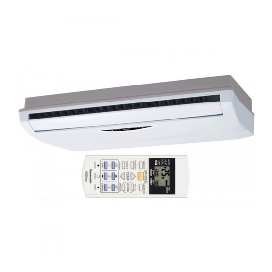
CS-E15DTEW CU-E15DBE / CS-E18DTEW CU-E18DBE / CS-E21DTES CU-E21DBE 2 Functions 2.1. Remote Control AUTO SPEED HEAT COOL TIMER TIMER OFF/ON MODE FAN SPEED POWERFUL AUTO TEMP AIR SWING QUIET MANUAL TIMER CANCEL CANCEL CHECK CLOCK RESET INVENTER TEMP OFF / ON I... -
Page 4: Indoor Unit
CS-E15DTEW CU-E15DBE / CS-E18DTEW CU-E18DBE / CS-E21DTES CU-E21DBE 2.2. Indoor Unit Automatic Operation Switch Quiet Mode • To provide quiet operation. • To run automatic operation, force cooling or heating operation, or change remote control 24-Hour Real Time Timer Control signal type. -
Page 5: Outdoor Unit
CS-E15DTEW CU-E15DBE / CS-E18DTEW CU-E18DBE / CS-E21DTES CU-E21DBE 2.3. Outdoor Unit Time Delay Safety Control 30 seconds Forced Operation Overload Protection Control Total Running Current Control Compressor Overheating Prevention Control IPM (Power Transistor) Overheating Protection Control Low Operation Frequency Protection Control... -
Page 6: Product Specifications
CS-E15DTEW CU-E15DBE / CS-E18DTEW CU-E18DBE / CS-E21DTES CU-E21DBE 3 Product Specifications 3.1. CS-E15DTEW CU-E15DBE Unit CS-E15DTEW CU-E15DBE Cooling Capacity 4.15 (0.90 - 4.55) kcal/h 3,570 (770 - 3,910) BTU/h 14,200 (3,070 - 15,500) Heating Capacity 5.17 (0.90 - 6.30) kcal/h... - Page 7 CS-E15DTEW CU-E15DBE / CS-E18DTEW CU-E18DBE / CS-E21DTES CU-E21DBE Unit CS-E15DTEW CU-E15DBE Pipe Size inch G (gas side) ; 1/2” G (gas side) ; 1/2” (Flare piping) inch L (liquid side) ; 1/4” L (liquid side) ; 1/4” Drain Inner diameter —...
-
Page 8: Cs-E18Dtew Cu-E18Dbe
CS-E15DTEW CU-E15DBE / CS-E18DTEW CU-E18DBE / CS-E21DTES CU-E21DBE 3.2. CS-E18DTEW CU-E18DBE Unit CS-E18DTEW CU-E18DBE Cooling Capacity 5.00 (0.90 - 5.40) kcal/h 4,300 (770 - 4,640) BTU/h 17,100 (3,070 - 18,400) Heating Capacity 6.10 (0.90 - 7.60) kcal/h 5,250 (770 - 6,540) - Page 9 CS-E15DTEW CU-E15DBE / CS-E18DTEW CU-E18DBE / CS-E21DTES CU-E21DBE Unit CS-E18DTEW CU-E18DBE Drain Inner diameter — Hose Length 0.66 — Power Cord Length —— — Number of core-wire — Dimensions Height inch (mm) 21 - 9/32 (540) 29 - 17/32 (750)
-
Page 10: Cs-E21Dtes Cu-E21Dbe
CS-E15DTEW CU-E15DBE / CS-E18DTEW CU-E18DBE / CS-E21DTES CU-E21DBE 3.3. CS-E21DTES CU-E21DBE Unit CS-E21DTES CU-E21DBE Cooling Capacity 5.80 (0.90 - 6.60) kcal/h 4,990 (770 - 5,680) BTU/h 19,800 (3,070 - 22,500) Heating Capacity 6.80 (0.90 - 8.10) kcal/h 5,850 (770 - 6,970) - Page 11 CS-E15DTEW CU-E15DBE / CS-E18DTEW CU-E18DBE / CS-E21DTES CU-E21DBE Unit CS-E21DTES CU-E21DBE Drain Inner diameter — Hose Length 0.66 — Power Cord Length —— — Number of core-wire — Dimensions Height inch (mm) 21 - 9/32 (540) 29 - 17/32 (750)
-
Page 12: Dimensions
CS-E15DTEW CU-E15DBE / CS-E18DTEW CU-E18DBE / CS-E21DTES CU-E21DBE 4 Dimensions 4.1. Indoor Unit & Remote Control 4.1.1. CS-E15DTEW CS-E18DTEW CS-E21DTES... -
Page 13: Outdoor Unit
CS-E15DTEW CU-E15DBE / CS-E18DTEW CU-E18DBE / CS-E21DTES CU-E21DBE 4.2. Outdoor Unit 4.2.1. CU-E15DBE CU-E18DBE CU-E21DBE... -
Page 14: Refrigeration Cycle Diagram
CS-E15DTEW CU-E15DBE / CS-E18DTEW CU-E18DBE / CS-E21DTES CU-E21DBE 5 Refrigeration Cycle Diagram... -
Page 15: Block Diagram
CS-E15DTEW CU-E15DBE / CS-E18DTEW CU-E18DBE / CS-E21DTES CU-E21DBE 6 Block Diagram... -
Page 16: Wiring Diagram
CS-E15DTEW CU-E15DBE / CS-E18DTEW CU-E18DBE / CS-E21DTES CU-E21DBE 7 Wiring Diagram... -
Page 17: Operation Details
CS-E15DTEW CU-E15DBE / CS-E18DTEW CU-E18DBE / CS-E21DTES CU-E21DBE 8 Operation Details 8.1. Basic Operation Inverter control, which equipped with a microcomputer in determining the most suitable operating mode as time passes, automatically adjust output power for maximum comfort always. In order to achieve the suitable operation mode, the microcomputer maintains the set temperature by measuring the temperature of environment and performing temperature shifting. -
Page 18: Cooling Operation
CS-E15DTEW CU-E15DBE / CS-E18DTEW CU-E18DBE / CS-E21DTES CU-E21DBE 8.1.2. Cooling Operation 8.1.2.1. Thermostat control • Compressor is OFF when Intake Air Temperature - Internal Setting Temperature < -1.5°C. • Compressor is ON after waiting for 3 minutes, if the Intake Air Temperature - Internal Setting Temperature > Compressor OFF point. -
Page 19: Automatic Operation
CS-E15DTEW CU-E15DBE / CS-E18DTEW CU-E18DBE / CS-E21DTES CU-E21DBE 8.1.5. Automatic Operation This mode can be set using remote control and the operation is decided by remote control setting temperature, indoor intake air temperature and outdoor air temperature. During operation mode judgment, indoor fan motor (with speed of Lo-) and outdoor fan motor are running for 30 seconds to detect the indoor intake and outdoor air temperature. -
Page 20: Indoor Fan Motor Operation
CS-E15DTEW CU-E15DBE / CS-E18DTEW CU-E18DBE / CS-E21DTES CU-E21DBE 8.1.6. Indoor Fan Motor Operation A. Basic Rotation Speed (rpm) • Required rotation speed for fan is set to respond to the remote control setting (10 rpm unit) [Cooling, Dry, Fan] Remote Control —... - Page 21 CS-E15DTEW CU-E15DBE / CS-E18DTEW CU-E18DBE / CS-E21DTES CU-E21DBE 2. Heating ii. Auto Fan Speed 1. Cooling...
- Page 22 CS-E15DTEW CU-E15DBE / CS-E18DTEW CU-E18DBE / CS-E21DTES CU-E21DBE 2. Heating Note: a. UP: • If move from Lo, the fan speed will be shifted to Maximum 1520 rpm. • If move from Maximum, the fan speed no change. • In up zone, 10 rpm is added for every 10s until Maximum 1520 rpm.
-
Page 23: Outdoor Fan Motor Operation
CS-E15DTEW CU-E15DBE / CS-E18DTEW CU-E18DBE / CS-E21DTES CU-E21DBE 8.1.7. Outdoor Fan Motor Operation Outdoor fan motor is operated with 15 fan speed. It starts when compressor starts operation and it stops 30 seconds after compressor stops operation for speed no.8. - Page 24 CS-E15DTEW CU-E15DBE / CS-E18DTEW CU-E18DBE / CS-E21DTES CU-E21DBE 2. Manual vertical airflow direction can be set using remote control; the angles of the vane are as stated above and the positions of the vane are as Figure 2 below. When the air conditioner is stopped using remote control, the vane will shift to close position.
- Page 25 CS-E15DTEW CU-E15DBE / CS-E18DTEW CU-E18DBE / CS-E21DTES CU-E21DBE 8.1.9.1. Quiet operation (Heating) A. Purpose To provide quiet heating operation compare to normal operation. B. Control condition a. Quiet operation start condition • When “quiet” button at remote control is pressed.
-
Page 26: Indication Panel
CS-E15DTEW CU-E15DBE / CS-E18DTEW CU-E18DBE / CS-E21DTES CU-E21DBE (c) Heating Operation 8.1.11. 24-Hour Real Time Timer Control ON Timer ON timer can be set using remote control, the unit with timer set will start operate earlier than the setting time. This is to provide a comfortable environment when reaching the set ON time. -
Page 27: Protection Control Features
CS-E15DTEW CU-E15DBE / CS-E18DTEW CU-E18DBE / CS-E21DTES CU-E21DBE 8.2. Protection Control Features 8.2.1. Protection Control For All Operations 8.2.1.1. Time Delay Safety Control 1. The compressor will not start for three minutes after stop of operation. 2. This control is not applicable if the power supply is cut off for 20 seconds and on again or after 4-way valve deices condition. - Page 28 CS-E15DTEW CU-E15DBE / CS-E18DTEW CU-E18DBE / CS-E21DTES CU-E21DBE 8.2.1.5. Compressor Overheating Prevention Control Instructed frequency for compressor operation will be regulated by compressor discharge temperature. The changes of frequency are as below figure. 8.2.1.6. Low Pressure Prevention Control (Gas Leakage Detection) a.
-
Page 29: Outdoor Air Temperature Control
CS-E15DTEW CU-E15DBE / CS-E18DTEW CU-E18DBE / CS-E21DTES CU-E21DBE 8.2.2. Protection Control For Cooling & Soft Dry Operation 8.2.2.1. Outdoor Air Temperature Control The compressor operating frequency is regulated in accordance to the outdoor air temperature as shown in the diagram below. - Page 30 CS-E15DTEW CU-E15DBE / CS-E18DTEW CU-E18DBE / CS-E21DTES CU-E21DBE 3. Control contents In the outdoor fan speed no. i) In protectorate Domain A is referred to as min 660 rpm. ii) In protectorate Domain B, it is referred to as min 600 rpm.
- Page 31 CS-E15DTEW CU-E15DBE / CS-E18DTEW CU-E18DBE / CS-E21DTES CU-E21DBE 8.2.3. Protection Control For Heating Operation 8.2.3.1. Intake Air Temperature Control Compressor will operate at Max freq 94 (E15D), 128 (E18D, E21D) Hz if either one of the below conditions occur: 1. When the indoor intake air temperature is less than 21°C and remote control setting fan speed is lower Me-.
-
Page 32: Deice Control
CS-E15DTEW CU-E15DBE / CS-E18DTEW CU-E18DBE / CS-E21DTES CU-E21DBE 8.2.3.4. Deice Control • Deice starts to prevent frosting at outdoor heat exchanger. • Deice operation detection commences after minimum 60 minutes of Heating Operation. • The outdoor heat exchanger temperature drops below 3°C for long period (minimum 40 minutes) during compressor is in... -
Page 33: Operating Instructions
CS-E15DTEW CU-E15DBE / CS-E18DTEW CU-E18DBE / CS-E21DTES CU-E21DBE 9 Operating Instructions... - Page 34 CS-E15DTEW CU-E15DBE / CS-E18DTEW CU-E18DBE / CS-E21DTES CU-E21DBE...
- Page 35 CS-E15DTEW CU-E15DBE / CS-E18DTEW CU-E18DBE / CS-E21DTES CU-E21DBE...
- Page 36 CS-E15DTEW CU-E15DBE / CS-E18DTEW CU-E18DBE / CS-E21DTES CU-E21DBE...
- Page 37 CS-E15DTEW CU-E15DBE / CS-E18DTEW CU-E18DBE / CS-E21DTES CU-E21DBE...
- Page 38 CS-E15DTEW CU-E15DBE / CS-E18DTEW CU-E18DBE / CS-E21DTES CU-E21DBE...
- Page 39 CS-E15DTEW CU-E15DBE / CS-E18DTEW CU-E18DBE / CS-E21DTES CU-E21DBE...
- Page 40 CS-E15DTEW CU-E15DBE / CS-E18DTEW CU-E18DBE / CS-E21DTES CU-E21DBE...
-
Page 41: Installation And Servicing Air Conditioner Using R410A
CS-E15DTEW CU-E15DBE / CS-E18DTEW CU-E18DBE / CS-E21DTES CU-E21DBE 10 Installation And Servicing Air Conditioner Using R410A 10.1. Outline 10.1.1. About R410A Refrigerant 1. Converting air conditioners to R410A Since it was declared in1974 that chlorofluorocarbons (CFC), hydro chlorofluorocarbons (HCFC) and other substances pose a destructive danger to the ozone layer in the earth´s upper stratosphere (20 to 40 km above the earth), measures have been... -
Page 42: Tools For Installing/Servicing Refrigerant Piping
CS-E15DTEW CU-E15DBE / CS-E18DTEW CU-E18DBE / CS-E21DTES CU-E21DBE d. R410A refrigerating machine oil Conventionally, mineral oil or a synthetic oil such as alkylbenzene has been used for R22 refrigerating machine oil. Because of the poor compatibility between R410A and conventional oils like mineral oil, however, there is a tendency for the refrigerating machine oil to collect in the refrigerating cycle. -
Page 43: R410A Tools
CS-E15DTEW CU-E15DBE / CS-E18DTEW CU-E18DBE / CS-E21DTES CU-E21DBE 10.2.2. R410A Tools 1. Copper tube gauge for clearance adjustment (used when flaring with the conventional flaring tool (clutch type)) • This gauge makes it easy to set the clearance for the copper tube to 1.0-1.5 mm from the clamp bar of the... - Page 44 CS-E15DTEW CU-E15DBE / CS-E18DTEW CU-E18DBE / CS-E21DTES CU-E21DBE 5. Charging hose • The pressure resistance of the charging hose has been raised to match the higher pressure of R410A. The hose material has also been changed to suit HFC use, and the size of the fitting has been changed to match the manifold ports.
- Page 45 CS-E15DTEW CU-E15DBE / CS-E18DTEW CU-E18DBE / CS-E21DTES CU-E21DBE 8. Electronic scale for refrigerant charging • Because of the high pressure and fast vaporizing speed of R410A, the refrigerant cannot be held in a liquid phase inside the charging cylinder when charging is...
-
Page 46: Refrigerant Piping Work
CS-E15DTEW CU-E15DBE / CS-E18DTEW CU-E18DBE / CS-E21DTES CU-E21DBE 10.3. Refrigerant Piping Work 10.3.1. Piping Materials It is recommended that you use copper and copper alloy jointless pipes with a maximum oil adherence of 40 mg/10m. Do not use pipes that are crushed, deformed, or discolored (especially the inside surface). If these inferior pipes are used, impurities may clog the expansion valves or capillaries. - Page 47 CS-E15DTEW CU-E15DBE / CS-E18DTEW CU-E18DBE / CS-E21DTES CU-E21DBE Table 11 R410A flaring dimensions Nominal Outside Wall thickness A (mm) diameter diameter (mm) R410A flaring Conventional flaring tool (mm) tool, clutch type Clutch type Wing-nut type 6.35 0 - 0.5 1.0 - 1.5 1.5 - 2.0...
-
Page 48: Installation, Transferring, Servicing
CS-E15DTEW CU-E15DBE / CS-E18DTEW CU-E18DBE / CS-E21DTES CU-E21DBE b. Copper pipes Use only copper pipes with the thickness given in table 10, and with minimal impurities. Because the surface of the pipe is exposed, you should take special care, and also take measures such as marking the pipes to make sure they are easily distinguished from other piping materials, to prevent mistaken use. -
Page 49: Transferring (Using New Refrigerant Piping)
CS-E15DTEW CU-E15DBE / CS-E18DTEW CU-E18DBE / CS-E21DTES CU-E21DBE 10.4.2. Transferring (Using New Refrigerant Piping) 1. Removing the unit a. Collecting the refrigerant into the outdoor unit by pumping down The refrigerant can be collected into the outdoor unit (pumping down) by pressing the TEST RUN button, even when the temperature of the room is low. -
Page 50: Recharging Refrigerant During Servicing
CS-E15DTEW CU-E15DBE / CS-E18DTEW CU-E18DBE / CS-E21DTES CU-E21DBE 10.4.5. Recharging Refrigerant During Servicing When recharging is necessary, insert the specified amount of new refrigerant in accordance with the following procedure. 1. Connect the charging hose to the service port of the outdoor unit. - Page 51 CS-E15DTEW CU-E15DBE / CS-E18DTEW CU-E18DBE / CS-E21DTES CU-E21DBE 10.4.6. Brazing As brazing requires sophisticated techniques and experiences, it must be performed by a qualified person. In order to prevent the oxide film from occurring in the pipe interior during brazing, it is effective to proceed with brazing while letting dry nitrogen gas (N ) flow.
-
Page 52: Installation Instructions
CS-E15DTEW CU-E15DBE / CS-E18DTEW CU-E18DBE / CS-E21DTES CU-E21DBE 11 Installation Instructions Required tools for Installation Works 1. Philips screw driver 5. Spanner 9. Gas leak detector 13. Multimeter 2. Level gauge 6. Pipe cutter 10. Measuring tape 14. Torque wrench 18 N.m (1.8 kgf.m) - Page 53 CS-E15DTEW CU-E15DBE / CS-E18DTEW CU-E18DBE / CS-E21DTES CU-E21DBE CAUTION 1. This equipment must be earthed. It may cause electrical shock if grounding is not perfect. 2. Do not install the unit at place where leakage of flammable gas may occur. In case gas leaks and accumulates at surrounding of the unit, it may cause fire.
- Page 54 CS-E15DTEW CU-E15DBE / CS-E18DTEW CU-E18DBE / CS-E21DTES CU-E21DBE Attached accessories Indoor/Outdoor Unit Installation Diagram Applicable piping kit CZ-4F5, 7, 10BP Select the best location INDOOR UNIT • There should not be any heat source or steam near the unit. • There should not be any obstacles blocking the air circulation.
-
Page 55: Indoor Unit
CS-E15DTEW CU-E15DBE / CS-E18DTEW CU-E18DBE / CS-E21DTES CU-E21DBE 11.2. Indoor Unit 11.2.1. SELECT THE BEST LOCATION (Refer to “Select the best location” section) 11.2.2. HOW TO FIX INSTALLATION PARTS Installation on the ceiling • Measure and mark the position for the Suspension bolts and the piping hole. -
Page 56: Indoor Unit Installation
CS-E15DTEW CU-E15DBE / CS-E18DTEW CU-E18DBE / CS-E21DTES CU-E21DBE 11.2.3. TO DRILL A HOLE IN THE WALL AND INSTALL A SLEEVE OF PIPING 1. Insert the piping sleeve to the hole. 2. Fix the bushing to the sleeve. 3. Cut the sleeve until it extrudes about 15 mm from the wall. -
Page 57: Connect The Cable To The Indoor Unit
CS-E15DTEW CU-E15DBE / CS-E18DTEW CU-E18DBE / CS-E21DTES CU-E21DBE 11.2.5. CONNECT THE CABLE TO THE INDOOR UNIT Open the control box at the bottom end of the chassis and connect the cable through the hole. • Connect the wires to the terminals on the control board individually according to the outdoor unit connection. -
Page 58: Outdoor Unit
CS-E15DTEW CU-E15DBE / CS-E18DTEW CU-E18DBE / CS-E21DTES CU-E21DBE 11.3. Outdoor Unit 11.3.1. SELECT THE BEST LOCATION (Refer to “Select the best location” section) 11.3.2. INSTALL THE OUTDOOR UNIT At the best location, start installation according to Indoor- Outdoor Unit Installation Diagram. -
Page 59: Evacuation Of The Equipment
CS-E15DTEW CU-E15DBE / CS-E18DTEW CU-E18DBE / CS-E21DTES CU-E21DBE CUTTING AND FLARING THE PIPING 1. Please cut using pipe cutter and then remove the burrs. 2. Remove the burrs by using reamer. If burrs is not removed, gas leakage may be caused. -
Page 60: Connect The Cable To The Outdoor Unit
CS-E15DTEW CU-E15DBE / CS-E18DTEW CU-E18DBE / CS-E21DTES CU-E21DBE CAUTION • If gauge needle does not move from 0 cmHg (0 MPa) to -76 cmHg (-0.1 MPa), in step 3 above take the following measure: • If the leak stops when the piping connections are tightened further, continue working from step 3. - Page 61 CS-E15DTEW CU-E15DBE / CS-E18DTEW CU-E18DBE / CS-E21DTES CU-E21DBE DISPOSAL OF OUTDOOR UNIT DRAIN WATER • If a drain elbow is used, the unit should be placed on a stand which is taller than 3 cm. • If the unit is used in an area where temperature falls below 0°C for 2 or 3 days in succession, it is recommended not to...
- Page 62 CS-E15DTEW CU-E15DBE / CS-E18DTEW CU-E18DBE / CS-E21DTES CU-E21DBE REMO-CON NO. CHANGE IN REMOTE CONTROL 1. Remove the batteries from the battery compartment of the Remote Control. 2. On the left side of the battery compartment, there is a small opening in the centre in which Jumper (J_A) can be seen.
-
Page 63: Servicing Information
CS-E15DTEW CU-E15DBE / CS-E18DTEW CU-E18DBE / CS-E21DTES CU-E21DBE 12 Servicing Information Caution: • Pb free solder has a higher melting point than standard solder; Typically the melting point is 50 - 70°F (30 - 40°C) higher. Please use a high temperature soldering iron. In case of the soldering iron with temperature control, please set it to 700 ± 20°F (370 ± 10°C). - Page 64 CS-E15DTEW CU-E15DBE / CS-E18DTEW CU-E18DBE / CS-E21DTES CU-E21DBE Troubleshooting Air Conditioner Refrigeration cycle system In order to diagnose malfunctions, make sure that there are no electrical problems before inspecting the refrigeration cycle. Such problems include insufficient insulation, problem with the power source, malfunction of a compressor and a fan.
-
Page 65: Breakdown Self Diagnosis Function
CS-E15DTEW CU-E15DBE / CS-E18DTEW CU-E18DBE / CS-E21DTES CU-E21DBE 1. Relationship between the condition of the air conditioner and pressure and electric current Cooling Mode Heating Mode Condition of the air conditoner Low Pressure High Pressure Electric current Low Pressure High Pressure... -
Page 66: Error Code Table
CS-E15DTEW CU-E15DBE / CS-E18DTEW CU-E18DBE / CS-E21DTES CU-E21DBE Error Codes Table Diagnosis Abnormality / Protection control Abnormality Emergency Primary location to verify display Judgement operation • Internal / external cable connections Indoor / outdoor abnormal > 1 min after starting... -
Page 67: Remote Control
CS-E15DTEW CU-E15DBE / CS-E18DTEW CU-E18DBE / CS-E21DTES CU-E21DBE 12.3. Remote Control Remote Control Reset • When the batteries are inserted for the first time or the batteries are replaced, you may notice the indications at remote control’s display screen blink continuously and not functionable. -
Page 68: Auto Off/On Button
CS-E15DTEW CU-E15DBE / CS-E18DTEW CU-E18DBE / CS-E21DTES CU-E21DBE 12.4. Auto OFF/ON Button • The “Auto OFF/ON” button is used to operate the air conditioner if remote control is misplaced or malfunctioning. • Auto operation is started once “Auto OFF/ON” button is pressed. -
Page 69: Disassembly Of Parts
CS-E15DTEW CU-E15DBE / CS-E18DTEW CU-E18DBE / CS-E21DTES CU-E21DBE 12.5. Disassembly of Parts 12.5.1. Front Grille Removal Procedure 1. Remove the intake grille and air filter from the front grille (Fig. 1). (Fig. 1) 2. Remove the front grille by removing the screws (Fig. 2). - Page 70 CS-E15DTEW CU-E15DBE / CS-E18DTEW CU-E18DBE / CS-E21DTES CU-E21DBE 12.5.2. Fan Motor Removal Procedure 1. Remove two Air Guider Blower Wheel (Fig. 4). (Fig. 4) 2. Remove Fan Motor by: - Release the connectors Fan Motor (Fig. 5). - Remove the Fan Motor supportor screws (Fig. 5).
-
Page 71: Outdoor Electronic Controller Removal Procedure
CS-E15DTEW CU-E15DBE / CS-E18DTEW CU-E18DBE / CS-E21DTES CU-E21DBE 12.5.4. Outdoor Electronic Controller Removal Procedure 1. Remove the top panel and front panel • Be save to return the wiring to its original position • There are many high voltage components within the heat sink cover so never touch the interior during operation. -
Page 72: Technical Data
CS-E15DTEW CU-E15DBE / CS-E18DTEW CU-E18DBE / CS-E21DTES CU-E21DBE 13 Technical Data 13.1. Operation Characteristics 13.1.1. CS-E15DTEW CU-E15DBE... - Page 73 CS-E15DTEW CU-E15DBE / CS-E18DTEW CU-E18DBE / CS-E21DTES CU-E21DBE 13.1.2. CS-E18DTEW CU-E18DBE...
- Page 74 CS-E15DTEW CU-E15DBE / CS-E18DTEW CU-E18DBE / CS-E21DTES CU-E21DBE 13.1.3. CS-E21DTES CU-E21DBE...
-
Page 75: Sensible Capacity Chart
CS-E15DTEW CU-E15DBE / CS-E18DTEW CU-E18DBE / CS-E21DTES CU-E21DBE 13.2. Sensible Capacity Chart G CS-E15DTEW CU-E15DBE Outdoor Temp. (°C) Indoor wet bulb temp. 17.0°C 4.12 3.12 1.18 3.85 2.99 1.27 3.58 2.88 1.36 3.25 2.73 1.47 19.0°C 4.15 1.29 19.5°C 4.52 3.27... -
Page 76: Exploded View (Indoor Unit)
CS-E15DTEW CU-E15DBE / CS-E18DTEW CU-E18DBE / CS-E21DTES CU-E21DBE 14 Exploded View (Indoor Unit) 14.1. CS-E15DTEW CS-E18DTEW CS-E21DTES Note: The above exploded view is for the purpose of parts disassembly and replacement. The non-numbered parts are not kept as standard service parts. -
Page 77: Replacement Parts List (Indoor Unit)
CS-E15DTEW CU-E15DBE / CS-E18DTEW CU-E18DBE / CS-E21DTES CU-E21DBE 15 Replacement Parts List (Indoor Unit) 15.1. CS-E15DTEW CS-E18DTEW CS-E21DTES REF NO. DESCRIPTION & NAME QTY. CS-E15DTEW CS-E18DTEW CS-E21DTES REMARKS ← ← CHASSY COMPLETE CWD50C1419 ← ← FAN MOTOR CWA921158 ← ←... -
Page 78: Exploded View (Outdoor Unit)
CS-E15DTEW CU-E15DBE / CS-E18DTEW CU-E18DBE / CS-E21DTES CU-E21DBE 16 Exploded View (Outdoor Unit) 16.1. CU-E15DBE CU-E18DBE CU-E21DBE Note: The above exploded view is for the purpose of parts disassembly and replacement. The non-numbered parts are not kept as standard service parts. -
Page 79: Replacement Parts List (Outdoor Unit)
CS-E15DTEW CU-E15DBE / CS-E18DTEW CU-E18DBE / CS-E21DTES CU-E21DBE 17 Replacement Parts List (Outdoor Unit) 17.1. CU-E15DBE CU-E18DBE CU-E21DBE REF NO. DESCRIPTION & NAME QTY. CU-E15DBE CU-E18DBE CU-E21DBE REMARKS ← ← CHASSY ASSY CWD50K2085 ← ← ANTI-VIBRATION BUSHING CWH50077 ← ←... -
Page 80: Electronic Circuit Diagram
CS-E15DTEW CU-E15DBE / CS-E18DTEW CU-E18DBE / CS-E21DTES CU-E21DBE 18 Electronic Circuit Diagram 18.1. Indoor Unit G CS-E15DTEW CS-E18DTEW CS-E21DTES SCHEMATIC DIAGRAM 1/3 MAIN ELECTRONIC CONTROLLER INDICATOR COMPLETE 100µ 0.1µ R102 R103 IC101 Vout F-TEST S-TEST C101 47µF 6.3V CN-DISP 5.1k... - Page 81 CS-E15DTEW CU-E15DBE / CS-E18DTEW CU-E18DBE / CS-E21DTES CU-E21DBE SCHEMATIC DIAGRAM 2/3 AN14 AN13 AN12 AN11 AN10 ADVV RESET 1µ IC01 1µ UPD784956GC IC(VPP) 150k 21 22 23 24 25 26 27 28 29 0.1µ...
- Page 82 CS-E15DTEW CU-E15DBE / CS-E18DTEW CU-E18DBE / CS-E21DTES CU-E21DBE SCHEMATIC DIAGRAM 3/3 FUSE01 (T 2A L 250V) DB01 AC01(BLK) IC03 IC04 ZNR01 0.047µ 511U 630V 220µ 470µF 3300µ 0.1µ 125uH 4700p (GRN) 4700p 1.3k AC02 0.01µ (WHT) 1.6k 0.1µ 2200p AC03 6.2k...
-
Page 83: Outdoor Unit
CS-E15DTEW CU-E15DBE / CS-E18DTEW CU-E18DBE / CS-E21DTES CU-E21DBE 18.2. Outdoor Unit G CU-E15DBE CU-E18DBE CU-E21DBE SCHEMATIC DIAGRAM 1/4 REACTOR GRY1 GRY2 ZNR3 PTC1 ERZV10D102 65µ 350V LJP7 LJP11 RY-AC1 LJP9 ZNR2 PTC2 ERZVEAV511 LJP10 100k 1/4W 850µ RY-PWR FUSE 400V... - Page 84 CS-E15DTEW CU-E15DBE / CS-E18DTEW CU-E18DBE / CS-E21DTES CU-E21DBE SCHEMATIC DIAGRAM 2/4 FUSE2 (T 3.15A L 250V) R111 R114 464k 464k 1/4W 1/4W R112 R115 ET529AK7NLAC CN-JP1 464k 464k 1A5-E 1/4W 1/4W 600V R154 R159 EG01Z 470µ 1/4W 1/4W R116 R125 R128 10.7k...
- Page 85 CS-E15DTEW CU-E15DBE / CS-E18DTEW CU-E18DBE / CS-E21DTES CU-E21DBE SCHEMATIC DIAGRAM 3/4 C113 0.1µ µ 0.047 C117 0.1µ 3900p 10µ 3900p 200k HRU0103A2 0.01µ 0.1µ 100µ 0.1µ 0.1µ 6.3V P42/TM9A1 P41/TM8810 P40/TMA10 P37/TM710 P74/IRQ00 P36/TM610 0.047µ P75/IRQ01 P35/TM510 P76/IRQ02 P77/IRQ03 P34/TM410...
- Page 86 CS-E15DTEW CU-E15DBE / CS-E18DTEW CU-E18DBE / CS-E21DTES CU-E21DBE SCHEMATIC DIAGRAM 4/4 C106 0.47µ 630V R138 HV1C1 33Ω 47µ 47µ 0.047µ 0.047µ 25V 1000p 47µ 0.047µ HV1C2 0.047µ 25V 470p 47µ 0.047µ HV1C3 0.047µ 25V YELLOW LVIC 470p 0.047µ 25V U OUT...
- Page 87 CS-E15DTEW CU-E15DBE / CS-E18DTEW CU-E18DBE / CS-E21DTES CU-E21DBE How to use electronic circuit diagram TIMER TABLE <INDOOR> Test mode Name Time (When test point Short-circuited) 4 way valve abnormality 4 min. 24 sec. Outdoor air temp. for Hz No. decision 30 min.
-
Page 88: Remote Control
CS-E15DTEW CU-E15DBE / CS-E18DTEW CU-E18DBE / CS-E21DTES CU-E21DBE 18.3. Remote Control... -
Page 89: Print Patternindoor Unit Printed Circuit Board
CS-E15DTEW CU-E15DBE / CS-E18DTEW CU-E18DBE / CS-E21DTES CU-E21DBE 18.4. Print Pattern Indoor Unit Printed Circuit Board... -
Page 90: Print Patternoutdoor Unit Printed Circuit Board View
CS-E15DTEW CU-E15DBE / CS-E18DTEW CU-E18DBE / CS-E21DTES CU-E21DBE 18.5. Print Pattern Outdoor Unit Printed Circuit Board View [PHAAM] Printed in Malaysia...
Need help?
Do you have a question about the CS-E15DTEW and is the answer not in the manual?
Questions and answers