Table of Contents
Advertisement
AUDIO/VIDEO CONTROL RECEIVER
RECEPTOR DE CONTROL DE AUDIO/VÍDEO
RX-889PGD
TV/CATV/DBS
VCR 1
DVD
DVD MUILTI
CD
TAPE/MD
TV/DBS
VIDEO
PHONO
FM/AM
VCR 1
VCR 2
ANALOG/DIGITAL
SLEEP
SURROUND
CNTR TONE
CNTR
1
2
3
ON/OFF
MENU
MENU
SURROUND
TEST
REAR-L
4
5
6
MODE
ENTER
ENTER
DISC
EFFECT
REAR-R
7
8
9
/P
SOUND
SEA MODE
SUBWOOFER
10
0
+10
RETURN
FM MODE/MUTING
100+
AUDIO/
TV/VCR
MENU
CATV/DBS
SET
RX-889P AUDIO/VIDEO CONTROL RECEIVER
TEXT
EXIT
DISPLAY
STANDBY
MPEG
TV VOL
CHANNEL
VOLUME
STANDBY/ON
TV/VIDEO
VCR 1
TAPE
MUTING
CONTROL
/REW
PLAY
FF/
DOWN
TUNING
UP
REC
STOP
PAUSE
PHONES
COMPULINK
Remote
RM-SRX889P
REMOTE CONTROL
DIGITAL SOURCE FORMAT
DOLBY/DTS/MPEG
DOLBY
LINEAR
SURROUND ON/OFF
DTS
DIGITAL
PCM
INPUT
DSP MODE
SEA MODE
ANALOG/DIGITAL
FM/AM TUNING
TUNER PRESET
TUNER/SEA MEMORY
FM MODE
SPEAKERS
BALANCE/SURROUND
1
2
ADJUST
SEA ADJUST
SETTING
SOUND SELECT
LOUDNESS
ONE TOUCH OPERATION
INPUT ATT
SOURCE NAME
INSTRUCTIONS
MANUAL DE INSTRUCCIONES
MASTER VOLUME
D I G I T A L
–
+
DVD
CD
TV SOUND/DBS
PHONO
VCR 1
TAPE/MD
VCR 2
FM
VIDEO
AM
MULTI JOG
SOURCE SELECTOR
VIDEO
S-VIDEO
VIDEO
L
AUDIO
R
1 BIT P-E-M D-D-COMVERTER
For Customer Use:
D I G I T A L
Enter below the Model No. and Serial
No. which are located either on the rear,
bottom or side of the cabinet. Retain this
information for future reference.
Model No.
Serial No.
LVT0178-001A
[US, UB]
Advertisement
Table of Contents

Subscribe to Our Youtube Channel
Related Manuals for JVC LVT0178-001A


Summary of Contents for JVC LVT0178-001A
- Page 1 VIDEO VIDEO AUDIO For Customer Use: Enter below the Model No. and Serial No. which are located either on the rear, bottom or side of the cabinet. Retain this information for future reference. Model No. Serial No. LVT0178-001A [US, UB]...
- Page 2 Warnings, Cautions and Others / Avisos, precauciones y otras notas / Advertêcias, precauções e outras notas / CAUTION To reduce the risk of electrical shocks, fire, etc.: 1. Do not remove screws, covers or cabinet. 2. Do not expose this appliance to rain or moisture. PRECAUCIÓN Para reducir riesgos de choques eléctricos, incendio, etc.: 1.
- Page 3 Caution: Proper Ventilation To avoide risk of electric shock and fire and to protect from damage. Locate the apparatus as follows: Front: No obstructions open spacing. Sides: No obstructions in 10 cm from the sides. Top: No obstructions in 10 cm from the top. Back: No obstructions in 15 cm from the back Bottom:...
-
Page 4: Table Of Contents
Showing the Disc Information on the TV Screen ... 38 Searching for a Disc (Only for the CD player) ... 39 Entering the Disc Information ... 40 Operating JVC’s Audio/Video Components ... 42 Operating Other Manufacturers’ Video Equipment ... 44 Troubleshooting ... -
Page 5: Parts Identification
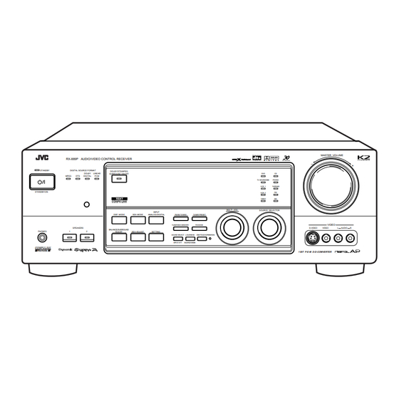
Parts Identification Become familiar with the buttons and controls on the receiver before use. Refer to the pages in parentheses for details. RX-889P AUDIO/VIDEO CONTROL RECEIVER STANDBY DIGITAL SOURCE FORMAT DOLBY/DTS/MPEG DOLBY LINEAR SURROUND ON/OFF MPEG DIGITAL STANDBY/ON DSP MODE SPEAKERS BALANCE/SURROUND PHONES... -
Page 6: Getting Started
Getting Started This section explains how to connect audio/video components and speakers to the receiver, and how to connect the power supply. Before Installation General • Be sure your hands are dry. • Turn the power off to all components. •... -
Page 7: Connecting The Speakers
AM Antenna Connections Snap the tabs on the loop into the ANTENNA slots of the base to assemble the FM 75 AM loop. COAXIAL LOOP AM Loop Antenna Outdoor single vinyl-covered wire Turn the loop until you have the best reception. Notes: •... -
Page 8: Connecting Audio/Video Components
About the speaker impedance The required speaker impedance of the front speakers does differ depending on whether both the FRONT SPEAKERS 1 and FRONT SPEAKERS 2 terminals are used or only one of them is used. CASE 1 When you connect only one set of front speakers Front speaker 1 Use front speakers with 8 —... - Page 9 Note: Any turntables incorporating a small-output cartridge such as an MC (moving-coil type) must be connected to this receiver through a commercial head amplifier or step-up transformer. Direct connection may result in insufficient volume. CD player CD player To audio output Cassette deck or MD recorder Cassette deck To audio input...
- Page 10 Video camera The VIDEO jacks on the front panel is convenient when connecting and disconnecting the equipment frequently. VIDEO S-VIDEO VIDEO AUDIO To audio output To S-video output To composite video output TV and/or DBS tuner RIGHT AUDIO RIGHT LEFT To audio output Connect the TV to the MONITOR...
-
Page 11: Connecting The Power Cord
Digital connections This receiver is equipped with three DIGITAL IN terminals — one digital coaxial terminal and two digital optical terminals. You can connect any component to any one of the digital terminals using the digital coaxial cable (not supplied) or digital optical cable (not supplied). -
Page 12: Basic Operations
Basic Operations The following operations are commonly used when you play any sound source. IMPORTANT: When using the remote control, check to see if its remote control mode selector is set to the correct position: To operate an audio system, TV, and VCR, set it to “AUDIO/TV/VCR.”... -
Page 13: Adjusting The Volume
When playing a digital source through a digital terminal • The DIGITAL SOURCE FORMAT lamps on the front panel indicate what type of the digital signal comes into the receiver. DIGITAL SOURCE FORMAT DOLBY LINEAR MPEG DIGITAL MPEG: Lights up when MPEG Multichannel signals (see page 21) come in. -
Page 14: Muting The Sound
Listening only with headphones 1. Connect a pair of headphones to the PHONES jack on the front panel. 2. Press SPEAKERS 1 and/or 2 so that no lamps on the buttons are turned on. CAUTION: Be sure to turn down the volume before connecting or putting on headphones, as high volume can damage both the headphones and your hearing. -
Page 15: Basic Settings
Basic Settings Some of the following settings are required after connecting and positioning your speakers in your listening room, while others will make operations easier. IMPORTANT: When using the remote control, check to see if its remote control mode selector is set to the correct position: To operate this receiver, set it to “AUDIO/TV/ VCR”... -
Page 16: Digital Input (Digital In) Terminal Setting
Digital Input (DIGITAL IN) Terminal Setting When you use the digital input terminals, you have to register what components are connected to which terminals (DIGITAL IN 1/2/3). Before you start, remember... • There is a time limit in doing the following steps. If the setting is canceled before you finish, start from step 1 again. -
Page 17: Setting The Speakers For The Dsp Modes
Setting the Speakers for the DSP Modes To obtain the best possible surround sound of the DSP modes, you have to register the information about the speakers arrangement after all connections are completed. Before you start, remember... • There is a time limit in doing the following steps. If the setting is canceled before you finish, start from step 1 again. - Page 18 Crossover Frequency Setting Small speaker cannot reproduce the bass sound very well. So, if you have used a small speaker any for the front, center, or rear channels, this receiver automatically reallocates the bass elements, originally assigned to the channel for which you have connected the small speaker, to another channel (for which you have connected the large speaker).
-
Page 19: Setting The Am Tuner Interval Spacing
Storing the Basic Settings and Adjustments — One Touch Operation JVC’s One Touch Operation function is used to assign and store different sound settings for each different playing source. By using this function, you do not have to change the settings every time you change the source. -
Page 20: Receiving Radio Broadcasts
Receiving Radio Broadcasts You can browse through all the stations or use the preset function to go immediately to a particular station. IMPORTANT: When using the remote control, check to see if its remote control mode selector is set to the correct position: To operate this receiver, set it to “AUDIO/TV/ VCR”... -
Page 21: Selecting The Fm Reception Mode
To tune in a preset station On the front panel: 1. Turn SOURCE SELECTOR to select the band (FM or AM). The last received station of the selected band is tuned in. 2. Press TUNER PRESET. 3. Turn MULTI JOG until you find the channel you want. -
Page 22: Using The Sea Modes
Using the SEA Modes The SEA (Sound Effect Amplifier) modes give you control of the way your music sounds. IMPORTANT: When using the remote control, check to see if its remote control mode selector is set to the correct position: To operate this receiver, set it to “AUDIO/TV/ VCR”... -
Page 23: Using The Dsp Modes
The 3D-PHONIC mode is the result of research on sound localization technology carried out at JVC for many years. This mode can be used when the front speakers are connected to this receiver (without respect to the rear/center speaker connection). -
Page 24: Surround Modes
– with DTS Digital Surround (bearing the mark – with MPEG Multichannel (bearing the mark you can use JVC Theater Surround. • When playing a source encoded with Dolby Digital, with DTS Digital Surround, or MPEG Multichannel, “DIG THEATER” is selected automatically. -
Page 25: Available Dsp Modes According To The Speaker Arrangement
Available DSP Modes According to the Speaker Arrangement Available DSP modes will vary depending on how many speakers are used with this receiver. Make sure that you have set the speaker information correctly (see page 14). Speaker arrangements Front Front speaker speaker Front... -
Page 26: Adjusting The 3D-Phonic Modes
IMPORTANT: When using the remote control, check to see if its remote control mode selector is set to the correct position: To operate this receiver, set it to “AUDIO/TV/ VCR” (except when selecting the DBS tuner as the source). Adjusting the 3D-PHONIC Modes Once you have adjusted the 3D-PHONIC modes, the adjustment is memorized for each 3D-PHONIC mode. -
Page 27: Adjusting The Surround Modes
3. Adjust the effect level. 1) Press BALANCE/SURROUND ADJUST repeatedly until “DSP EFFECT” appears on the display. The display changes to show the current setting. 2) Turn MULTI JOG to select the effect level. • As you turn it, the effect level changes as follows: DSP EFFECT 1 DSP EFFECT 2... - Page 28 Notes: • You can adjust the speaker output levels without outputting the test tone. • No test tone comes out of the center speaker when “CENTER SPK” is set to “NONE” (see page 14). • No test tone comes out of the rear speakers when “REAR SPK” is set to “NONE”...
- Page 29 7. Press EFFECT to select an effect level you want. • Each time you press the button, the effect level changes as follows: DSP EFFECT 1 DSP EFFECT 5 As the number increases, JVC Theater Surround becomes stronger. CNTR MENU MENU REAR•L...
-
Page 30: Activating The Dsp Modes
DSP EFFECT 1 DSP EFFECT 2 DSP EFFECT 5 DSP EFFECT 4 As the number increases, JVC Theater Surround becomes stronger. Activating the DSP Modes You can use only one DSP mode at a time. When a DSP mode is activated, another DSP mode is canceled if in use. - Page 31 • Each time you press the button, the DSP modes change. (See page 22 for more details.) 2. Select and play a sound source. • To enjoy 3D-PHONIC and JVC Theater Surround, play back a software: – encoded with Dolby Surround and labeled with mark.
-
Page 32: Using The Dvd Multi Playback Mode
Using the DVD MULTI Playback Mode This receiver provides the DVD MULTI playback mode for reproducing the analog discrete output mode of the DVD player. Before playing back a DVD, refer also to the manual supplied with the DVD player. IMPORTANT: When using the remote control, check to see if its remote control mode selector is set to the correct... - Page 33 From the remote control: 1. Press DVD MULTI so that “DVD MULTI” appears on the display. Note: When you select “DVD MULTI” as the source to play, the DSP mode is canceled temporarily, and the SURROUND ON/OFF and SURROUND MODE buttons do not work. 2.
-
Page 34: Using The On-Screen Menus
Using the On-Screen Menus You can use the Menus on the TV screen to control the receiver. To use this function, you need to connect the TV to the MONITOR OUT jack on the rear panel (see page 7), and set the TV’s input mode to the proper position to which the receiver is connected. -
Page 35: Listening At Low Volume (Loudness)
Listening at Low Volume (Loudness) (Also see page 11) 1. Press MENU. The MAIN MENU appears on the TV. • Pressing one of the % / fi / @ / # buttons also displays the MAIN MENU. 2. Press % / fi to move to “SOUND CONTROL,”... -
Page 36: Activating The Dvd Multi Playback Mode
* “REAR R LEVEL”: Adjust the right rear speaker output level. * “CENTER TONE”: Select the center tone level. ** For JVC Theater Surround: “TEST TONE”: Output a test tone. “CENTER LEVEL”: Adjust the center speaker output level. ** “REAR L LEVEL”: Adjust the left rear speaker output... -
Page 37: Setting The Basic Setting Items
4. Press % / fi to move SEA ADJUST to “SEA ADJUST.” SEA USERMODE The SEA ADJUST menu appears. 5. Press % / fi / @ / # to adjust the SEA mode as you want. @ / # : Select the frequency ranges. % / fi... -
Page 38: Storing The Preset Stations
Storing the Preset Stations (Also see page 17) 1. Press MENU. The MAIN MENU appears on the TV. • Pressing one of the % / fi / @ / # buttons also displays the MAIN MENU. 2. Press % / fi to move to “TUNER CONTROL,”... -
Page 39: Compu Link Remote Control System
COMPU LINK Remote Control System The COMPU LINK remote control system allows you to operate JVC audio components through the remote sensor on the receiver. To use this remote control system, you need to connect JVC audio components through the COMPU LINK-3 (SYNCHRO) jacks (see below) in addition to the connections using cables with RCA pin plugs (see pages 5 and 6). -
Page 40: Text Compu Link Remote Control System
TEXT COMPU LINK Remote Control System The TEXT COMPU LINK remote control system has been newly developed to deal with the disc information recorded in the CD Text* and MDs. Using these information in the discs, you can operate the CD player or MD recorder equipped with the TEXT COMPU LINK remote control system through the receiver. -
Page 41: Showing The Disc Information On The Tv Screen
OPERATIONS To use this remote control system, you need to connect the TV to the MONITOR OUT jack on the rear panel (see page 7), and set the TV’s input mode to the proper position to which the receiver is connected. -
Page 42: Searching For A Disc (Only For The Cd Player)
Searching for a Disc (Only for the CD player) Search for a disc by its performer: 1. Press TEXT DISPLAY while “CD” is selected as the source. The Disc Information screen appears on the TV. 2. Press % / fi to move to “SEARCH,”... -
Page 43: Entering The Disc Information
Search for a disc by its genre: 1. Press TEXT DISPLAY while “CD” is selected as the source. The Disc Information screen appears on the TV. 2. Press % / fi to move to “SEARCH,” then press SET. The DISC SEARCH screen appears. - Page 44 4. Repeat step 3 until you finish putting a performer name (up to 32 characters). To insert a space, press % / fi / @ / # to move , then press SET. To correct an incorrect character: 1) Press % / fi / @ / # to move to + or =, then press SET until the incorrect character is selected.
-
Page 45: Operating Jvc's Audio/Video Components
Operating JVC’s Audio/Video Components You can operate JVC’s audio and video components with this receiver’s remote control, since control signals for JVC components are preset in the remote control. IMPORTANT: To operate JVC’s audio components using this remote control: • You need to connect JVC audio components through the COMPU LINK-3 (SYNCHRO) jacks (see page 36) in addition to the connections using cables with RCA pin plugs (see pages 5 and 6). - Page 46 • Aim the remote control directly at the remote sensor on the VCR, DVD player or TV, not on the receiver. • Some JVC VCRs can accept two types of the control signals — remote code “A” and “B.” Before using this remote control, make sure that the remote control code of the target VCR is set to code “A.”...
-
Page 47: Operating Other Manufacturers' Video Equipment
1 – 9, and 0. See the list on pages 46 and 47 to find the code. Examples: For a JVC product, press 0, 3, then 6. For a Hitachi product, press 0, 3, then 6. 5. Release TV/CATV/DBS The following buttons can be used for operating the TV (with the remote control mode selector set to “AUDIO/TV/VCR”):... - Page 48 1 – 9, and 0. See the list on pages 48 and 49 to find the code. Examples: For a JVC product, press 0, 0, then 8. For a Funai product, press 0, 0, then 0. 5. Release VCR 1 Following button can be used for operating the VCR (with the remote control mode selector set to “AUDIO/TV/VCR”):...
- Page 49 Manufacturers’ codes for TV -Mark Acura Admiral Aiko Akai 030, 208 Akura Alaron Alba 009, 036, 037 Amstrad 009, 037 Anam 003, 004, 009, 068, 161, 250, 425, 426 Anam National 161, 250, 425 Anitech 009, 068 003, 030 Arcam Archer Audinac Audiosonic...
- Page 50 Mivar Motorola 030, 060, 216 Multitech 009, 216 156, 166, 178 National 030, 036, 170 Neckermann 037, 554 Nicamagic Nikkai 037, 216, 264 Nikko 030, 092, 178 Nisato Nordmende Optimus 154, 166, 250 Optonica Orion Osaki Otto Versand 036, 037, 535, 554 Panama Panasonic 161, 226, 250...
- Page 51 Manufacturers’ codes for CATV converters Daeryung GoldStar LG Alps Memorex Panasonic Paragon Pulsar Quasar Runco Samsung Scientific Atlanta Seawoo TongKook 777, 840 Toshiba Zenith Manufacturers’ codes for VCR Admiral Adventura Aiko Aiwa 000, 037 Akai 041, 061, 281, 288 Akiba Alba 020, 072, 278 Ambassador...
- Page 52 Melectronic Memorex 000, 037, 046, 048, 104, 162, 240 Memphis Metz 037, 162, 195, 227 043, 061, 240 MGN Technology Minerva Minolta Mitsubishi 043, 048, 061, 067, 081, 173, 196 Motorola 000, 240 Multitech 000, 072 Murphy National 038, 040, 041, 067, 104, 370 Neckermann Nesco Nikko...
-
Page 53: Troubleshooting
Troubleshooting Use this chart to help you solve daily operational problems. If there is any problem you cannot solve, contact your JVC service center. PROBLEM The display does not light up. No sound from speakers. Sound from one speaker only. -
Page 54: Specifications
Specifications Amplifier Output Power Audio Audio Input Sensitivity/Impedance (1 kHz): Audio Input (DIGITAL IN)* : Audio Output Level: Signal-to-Noise Ratio (’66 IHF/DIN): Frequency Response (8 ohms): RIAA Phono Equalization: Loudness Control (Volume Control at –40 dB): SEA: Video Video Input Sensitivity/Impedance: Composite video: S-video: Video Output Level:... - Page 55 FM tuner (IHF) Tuning Range: Usable Sensitivity: 50 dB Quieting Sensitivity: Signal-to-Noise Ratio (IHF-A weighted): Total Harmonic Distortion: Stereo Separation at REC OUT: Alternate Channel Selectivity: Frequency Response: AM tuner Tuning Range: Usable Sensitivity: Signal-to-Noise Ratio General Power Requirements: Power Consumption: Dimensions (W x H x D): Mass: 87.50 MHz to 108.00 MHz...
- Page 56 Mains (AC) Line Instruction (not applicable for Europe, U.S.A., Canada, Australia and U.K.) Instrucción sobre la línea de la red (CA) (no aplicable para Europa, EE.UU., Canadá, Australia, ni el Reino Unido) Instrução sobre a tensão da rede eléctrica (CA) (não aplicável para a Europa, os E.U.A., o Canadá, a Austrália e o Reino Unido) VOLTAGE SELECTOR 220-240V...
Need help?
Do you have a question about the LVT0178-001A and is the answer not in the manual?
Questions and answers