Table of Contents
Advertisement
Advertisement
Table of Contents

Subscribe to Our Youtube Channel
Related Manuals for Magicar M871A


Summary of Contents for Magicar M871A
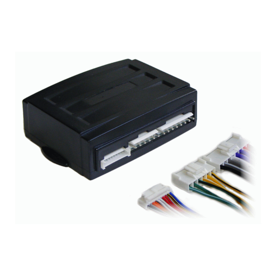
- Page 1 MAGICAR M871A Car alarm with two-way remote Installation guide...
- Page 2 MAGICAR M871A Car alarm with two-way remote Installation guide...
-
Page 3: Table Of Contents
TABLE OF CONTENTS I. INTRODUCTION..........................4 II. PLACING............................4 III. ADDITIONAL RELAY 12V CONNECTION................5 IV. WIRING ARRANGEMENT ......................6 V. Programming of optional functions ....................8 Programming menu No. 1......................9 Programming menu No.2 ......................9 VI. CALIBRATION OF THE FUNCTION – HAZARD LIGHT MODE ........10 ... -
Page 4: Introduction
I. INTRODUCTION MAGICAR M871A is a safety device with the highest level of security. Thanks to the 2- way remote with pager you will be immediately informed about possible car intrusion, as well as the manner of the intrusion even though you are too far from the car to hear the siren. -
Page 5: Additional Relay 12V Connection
WARNING! When installing a door contact, you must find an appropriate wire from the wire bundle of a car (it is important from the security point of view as well as that of remote starting) Wiring used for the alarm connection must not be broken nor its insulation damaged. -
Page 6: Wiring Arrangement
+12V line A If you want to connect shortly two wires by (-) signal. E.g.: Mostly used for installing alarm gas relays. line B impuls (-) IV. WIRING ARRANGEMENT CONNECTOR 1 – CN1 1 – red - +12V Power supply - power supply, connect to +12V. - Page 7 4 – red - Positive door switch input (+12V) 5 – orange/black - Negative parking lights input (-). When switching on Magicar M871A this will indicate the lights are on. 6 – orange - Positive parking lights input (+). When switching on Magicar M871A this will indicate the lights are on.
-
Page 8: Programming Of Optional Functions
LED indication CONNECTOR 9 - white RPS sensor CONNECTOR 10 - red Shock sensor 1 – black 3 – red - Grounding - Power supply of +12 V 4 – yellow 2 – white - Shock sensor input – second level (-) - Shock sensor input –... -
Page 9: Programming Menu No. 1
The function is supposed to be used with indirect closed doors scanning (from the roof light, etc.) 1-14 This function is available with CAN BUS Magicar module. In case of using the Read only function, Magicar only read CAN information (open door, trunk, hood, lock/unlock with OEM remote, etc.) -
Page 10: Calibration Of The Function - Hazard Light Mode
When function is enabled alarm will be armed or disarmed by original and system remote control. Alarm must be connected to CAN bus via CAN BUS Magicar module. Programming menu RESET In case you wish to set all the function back to the pre-set, you can do so by the following way. -
Page 11: Valet Mode
and the pulse mode (Mode 2). Mode 1 – continuous Mode 2 – pulse Output - Lights Lights - flashing Lights Control Unit Hazard Lights Switch Light output (CN1-3 or 4) Relay contact bypassing the hazard light switch Common input (CN1-2) Fig.1 Parking Lights output connected to the Hazard switch Calibration In case of using the mode 1 or 2 it is required to set the time of output closure. -
Page 12: Entering Valet Mode With Pin Code
Entering valet mode with PIN code. 1. Armed. 2. By opening the door, the alarm will be triggered. Siren will chirp. 3. Within 3 sec turn the ignition on/off three times. 4. Lights will flash once. 5. Push the button on RPS as many times, as your first number is. Intervals between the click/pushes must not be longer than 1.5 sec. -
Page 13: Changing Pin Code
Programming of security code (1111-9999): 1. Ignition on. 2. Open the door. 3. Push the button on RPS sensor 10 times. At every single click, LED will flash red once. Intervals between the click/pushes must not be longer than 1.5 sec. 4. - Page 14 Fig.4 Original built-in central power lock Fig.3 Original built-in central power lock & using compressor to control the switch. Note: Active time 4 sec. yellow/black COM1 yellow yellow/black yellow/white COM1 green/black yellow COM2 green yellow/white green/white green/black COM2 green Main line green/white Electric motor switch Unlock...
-
Page 15: Wiring Diagram
Wiring diagram Magicar M871A Lock (NO) 6 green/white Lock (COM) 5 green Wiring diagram fuse 15A Lock(NC) 4 green/black 1 violet door lock system Output to Starter kill (-250mA) Unlock (NO) 3 yellow/white Page 39 2 green Ignition input Unlock (COM) - Page 16 The car alarm system is designed for fitting into all kinds of cars with petrol and diesel engines with +12V volatge finished by a negative pole. Car alarm must be fitted following manufacturer‘s recommendation. The alarm installation to be carried out only by authorised service centre. Consult the choice of the service sentre with a manufacturer.
Need help?
Do you have a question about the M871A and is the answer not in the manual?
Questions and answers