Table of Contents
Advertisement
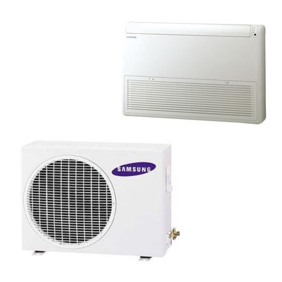
AIR CONDITIONER
FH052/070EAV1
UH052EAV1
Refer to the service manual in the GSPN(see the rear cover) for the more information.
SYSTEM AIR CONDITIONER
Basic :
Model :
Model Code : FH070EAV1
UH070EAV1
INDOOR UNIT
FH070EAV
FH070EAV1
FH052EAV1
FH052EAV1
THE FEATURE OF PRODUCT
Healthy air
Auto changeover
Long Lasting Outdoor Unit
Free Installation
OUTDOOR UNIT
UH070EAV
UH070EAV1
UH052EAV1
UH070EAV1
UH052EAV1
Advertisement
Table of Contents


Need help?
Do you have a question about the FH070EAV and is the answer not in the manual?
Questions and answers
heat pump does'nt work after power outage..I need instruction how to reset indoor switch pannel.
To reset the indoor switch panel on a Samsung FH070EAV heat pump after a power outage, follow these steps:
1. Unplug the power cord.
2. Wait for 30 seconds.
3. Plug the power cord back in.
4. Press the Power button on the remote control to turn on the unit.
5. Check the display board to ensure the air conditioner operates normally.
If the unit does not operate, further troubleshooting may be needed.
This answer is automatically generated