Table of Contents
Advertisement
This manual must be left with the homeowner for future reference.
This is a safety alert symbol and should never be ignored. When you see this symbol on labels or in
manuals, be alert to the potential for personal injury or death.
CAUTION
As with any mechanical equipment, personal injury
can result from contact with sharp sheet metal
edges. Be careful when you handle this equipment.
. . . . . . . . . . . . . . . . . . . . . . . . . . . . . . . .
. . . . . . . . . . . . . . . . . . . . . . . . . . . . . .
. . . . . . . . . . . . . . . . . . . . . . . . . . . . . . .
. . . . . . . . . . . . . . . . . . . . . . . . . . . . . . . . . . . . . . . .
. . . . . . . . . . . . . . . . . . . . . . . . . . . . . . .
. . . . . . . . . . . . . . . . . . . . . . . . . . . . . . . . . . . . . . . . . .
. . . . . . . . . . . . . . . . . . . . . . . . . . . . . . . . . . . .
02/11 Supersedes 01/11
02/11
*2P0211*
P.O. Box 799900, Dallas, TX 75379−9900
INSTALLATION INSTRUCTIONS
80AF1DF
Downflow Warm Air Gas Furnaces
TABLE OF CONTENTS
. . . . . . . . . . . . . . . . . . . . . . . . . .
. . . . . . . . . . . . . . . . . . . . . . . .
. . . . . . . . . . .
. . . . . . . . . . . . . .
Improper installation, adjustment, alteration, service
or maintenance can cause property damage, person-
al injury or loss of life. Installation and service must
be performed by a licensed professional installer (or
equivalent), service agency or the gas supplier.
2
. . . . . . . . . . . . . . . . . . . . . . . . . . . . . . . . . . . . . . . .
. . . . . . . . . . . . . . . . . . . . . . . . . . . . . . . . . . . . .
3
. . . . . . . . . . . . . . . . . . . . . . . . . . . . . . . . . . . . . . .
4
. . . . . . . . . . . . . . . . . . . . . . . . . . . . . . .
4
. . . . . . . . . . . . . . . . . . . . . . . . . . . . . . . . . . . .
4
. . . . . . . . . . . . . . . . . . . . . . . . . . . . . . . . . . . .
5
5
6
. . . . . . . . . . . . . . . . . . . . . . . . . . . . . . . . . . . . . . . .
9
. . . . . . . . . . . . . . . . . . . . . . . . . . . . . . . .
12
. . . . . . . . . . . . . . . . . . . . . . . . . . . . . . . .
12
Page 1
WARNING
. . . . . . . . . . . . . . . . . . . . . . . .
. . . . . . . . . . . . . . . . . . . . . . . . . . . . . .
. . . . . . . . . . . . . . . . . . . . . . . . . .
. . . . . . . . . . . . . . .
506719−01
*P506719-01*
13
20
22
25
26
27
27
27
28
29
32
33
34
Advertisement
Table of Contents

Related Manuals for Aire-Flo 80AF1DF


Summary of Contents for Aire-Flo 80AF1DF
-
Page 1: Table Of Contents
........80AF1DF Gas Furnace . -
Page 2: Unit Dimensions
GAS PIPING INLET 2−1/8 (54) Left (Either Side) 6−5/8 (168) Right 7−1/8 (181) Left Supply Supply 19−1/4 (489) (19) (19) FRONT VIEW SIDE VIEW 80AF1DF Model No. 045P12A 14−1/2 13−3/8 4−3/4 070P12A 090P16B 17−1/2 16−3/8 6−1/4 110P20C 19−7/8 19−1/2 Page 2... -
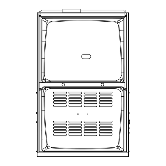
Page 3: Parts Arrangement
Parts Arrangement Blower Assembly Integrated Control Flue Chase Gas Valve Heat Exchanger Combustion Air Inducer Burner Assemlby Access Panel FIGURE 1 Page 3... -
Page 4: 80Af1Df Gas Furnace
In the USA, installation of gas furnaces must conform with local building codes. In the absence of local codes, units The 80AF1DF unit is shipped ready for installation in the must be installed according to the current National Fuel downflow position. The furnace is equipped fir installation Gas Code (ANSI-Z223.1). -
Page 5: Use Of Furnace As A Construction Heater
Use of Furnace as Construction Heater NOTE − The Commonwealth of Massachusetts stipu- It is not recommended using 80AF1DF units as a construc- lates these additional requirements: tion heater during any phase of construction. Very low re-... -
Page 6: Combustion, Dilution & Ventilation Air
In addition to providing combustion air, fresh outdoor air this section to install 80AF1DF furnaces to ensure efficient dilutes contaminants in the indoor air. These contami- and safe operation. You must consider combustion air nants may include bleaches, adhesives, detergents, sol- needs and requirements for exhaust vents and gas piping. - Page 7 confined, it might be necessary to bring in outdoor air for Air from Inside combustion if the structure does not provide enough air by If the confined space that houses the furnace adjoins a infiltration. If the furnace is located in a building of tight space categorized as unconfined, air can be brought in by construction with weather stripping and caulking around providing two permanent openings between the two...
- Page 8 EQUIPMENT IN CONFINED SPACE ALL AIR FROM OUTSIDE (Inlet Air from Crawlspace and Outlet Air to Ventilated Attic) CHIMNEY OR GAS VENT VENTILATION LOUVERS (Each end of attic) OUTLET WATER FURNACE HEATER INLET VENTILATION LOUVERS (For unheated crawl space) NOTE−The inlet and outlet air openings shall each have a free area of at least one square inch (645 ) per 4,000 Btu (1.17 kW) per hour of the total input rating of all equipment in the enclosure.
-
Page 9: Setting Equipment
Install the 80AF1DF gas furnace as shipped in the down- flow position only. Do not install the furnace hori- FIGURE 7 zontally. - Page 10 Allow for clearances to combustible materials as indicated WARNING on the unit nameplate. Minimum clearances for closet or al- cove installations are shown in figure 9. Improper installation of the furnace can result in per- sonal injury or death. Combustion and flue products Downflow Application Installation Clearances must never be allowed to enter the return air system or the living space.
-
Page 11: Downflow Installation
Installation on Non−Combustible Flooring (Figure 10) 1 − Cut floor opening keeping in mind clearances listed on unit rating plate. Also keep in mind gas supply connec- 80AF1DF UNIT tions, electrical supply, flue and air intake connections and sufficient installation and servicing clearances. -
Page 12: Filters
4 − In closet installations, it may be impossible to install sheet metal screws from the outside. In this case, 80AF1DF UNIT make plenum with a removable front and install screws from the inside (See figure 14). 5 − Make certain that an adequate seal is made. -
Page 13: Venting
(152 mm) from the furnace vent outlet. See figure the combustion chamber and/or heat exchanger. The 80AF1DF is not approved for use with horizontal venting. Venting Using a Masonry Chimney NOTE − Use these instructions as a guide. They do not su- The following additional requirements apply when a lined persede local codes. - Page 14 (interior or outside General Venting Requirements wall) is PROHIBITED. The chimney must first be lined Vent all 80AF1DF furnaces according to these instructions: with either type B1 vent or an insulated single wall flexible vent lining system which has been sized ac- 1 −...
- Page 15 6 − The entire length of single wall metal vent connector flue collar by self−drilling screws or other approved means, except vent connectors of listed type B vent shall be readily accessible for inspection, cleaning, material which shall be assembled according to the and replacement.
- Page 16 TABLE 5 Capacity of Type B Double−Wall Vents with Type B Double−Wall Connectors Serving a Single Category I Appliance Vent and Connector Diameter − D (inches) Height Lateral 3 Inch 4 Inch 5 Inch 6 Inch Appliance Input Rating in Thousands of Btu Per Hour (feet) (feet) NOTE −...
- Page 17 TABLE 6 Capacity of Type B Double−Wall Vents with Single−Wall Metal Connectors Serving a Single Category I Appliance Vent and Connector Diameter − D (inches) Height Lateral 3 Inch 4 Inch 5 Inch 6 Inch Appliance Input Rating in Thousands of Btu Per Hour (feet) (feet) NOTE −...
- Page 18 TABLE 7 Vent Connector Capacity Type B Double−Wall Vents with Type B Double−Wall Connectors Serving Two or More Category I Appliances Vent and Connector Diameter − D (inches) Vent Connector 3 Inch 4 Inch 5 Inch 6 Inch Height Rise Appliance Input Rating in Thousands of Btu Per Hour (feet) (feet)
- Page 19 TABLE 9 Vent Connector Capacity Type B Double−Wall Vents with Single−Wall Metal Connectors Serving Two or More Category I Appliances Vent and Connector Diameter − D (inches) Height Lateral 3 Inch 4 Inch 5 Inch 6 Inch Appliance Input Rating in Thousands of Btu Per Hour (feet) (feet) NOTE −...
-
Page 20: Gas Piping
Removal of the Furnace from Common Vent Resize the common venting system to the minimum vent pipe size determined by using the appropriate In the event that an existing furnace is removed from a tables in Appendix G. (These are in the current stan- venting system commonly run with separate gas ap- pliances, the venting system is likely to be too large to dards of the National Fuel Gas Code ANSI Z223.1. - Page 21 TABLE 11 Gas Pipe Capacity − ft /hr (m /hr) Nominal Length of Pipe − feet (m) Internal Iron Pipe Diameter Size inches inches (mm) (3.048) (6.096) (9.144) (12.192) (15.240) (18.288) (21.336) (24.384) (27.432) (30.480) (mm) .622 (12.7) (17.799) (4.96) (3.40) (2.75) (2.32)
-
Page 22: Electrical
Electric Code (ANSI/NFPA No. 70). A green ground wire is provided in the field make−up box. NOTE − The 80AF1DF furnace contains electronic compo- nents that are polarity sensitive. Make sure that the furnace is wired correctly and is properly grounded. - Page 23 Generator should have a wave form distortion of less 2 − When the 80AF1DF is running in the heating mode, the than 5% THD (total harmonic distortion). indoor blower will run on the heating speed.
- Page 24 80AF1DF Schematic Wiring Diagram FIGURE 23 Page 24...
-
Page 25: Integrated Control
INTEGRATED CONTROL (Automatic Hot Surface Ignition System) TERMINAL DESIGNATIONS Humidifier (120VAC) Input (120VAC) LINE Transformer (120VAC) XFMR Indoor Air Qality Accessory Air Cleaner (120VAC) Blower − Cooling Speed (120VAC) COOL Blower − Heating Speed (120VAC) HEAT Dead terminals to park alternate spd taps PARK Continuous blower CONT... -
Page 26: Unit Start−Up
Turning Off Gas to Unit" and call your service techni- The gas valve on the 80AF1DF unit will be equipped with a cian or gas supplier. gas control switch. Use only your hand to move the switch. -
Page 27: Gas Pressure Adjustment
The maximum car- GAS METER CLOCKING CHART bon monoxide reading should not exceed 50 ppm. Seconds for One Revolution TABLE 13 Natural 80AF1DF 80AF1DF Unit 1 cu ft 2 cu ft 1 cu ft... -
Page 28: Other Unit Adjustments
TABLE 14 Manifold Pressure Settings at all Altitudes Line Pressure in.wg. Model 0−2000 ft 2105−4500 ft. 4501−7500 ft Input Size 13.0 LP/propane 10.0 10.0 10.0 11.0 13.0 13.0 LP/propane 10.0 10.0 10.0 11.0 13.0 13.0 LP/propane 10.0 10.0 11.0 13.0 13.0 LP/propane 10.0... -
Page 29: Service
Filters NOTE − Termination of any unused motor leads must be All 80AF1DF filters are installed external to the unit. Filters insulated. should be inspected monthly. Clean or replace the filters 4 − Place unused blower speed tap on integrated control when necessary to ensure that the furnace operates prop- PARK"... - Page 30 Cleaning the Heat Exchanger and Burners tion air inducer. Be careful with the collector box gas- ket. If the gasket is damaged, it must be replaced to NOTE − Use papers or protective covering in front of the fur- prevent leakage. nace during cleaning.
- Page 31 10− Back wash using steam. Begin from the burner opening 21− If a leak is detected, shut gas and electricity off and on each clam. Steam must not exceed 275°F. repair leak. 11− To clean burners, run a vacuum cleaner with a soft brush 22−...
-
Page 32: Planned Service
Planned Service Return air duct − Must be properly attached and provide an air seal to the unit. The following items should be checked during an annual in- spection. Power to the unit must be shut off for the service Operating performance −... -
Page 33: Repair Parts List
Repair Parts Lit The following repair parts are available through independent dealers. When ordering parts, include the complete furnace model number listed on the CSA International nameplate −− Example: 80AF1DF045P12A−01. All service must be per- formed by a licensed professional installer (or equivalent), service agency, or gas supplier. Cabinet Parts Motor capacitor Blower housing cutoff plate... -
Page 34: Start−Up And Performance Checklist
Start−Up & Performance Check List UNIT SET UP (typical) Unit Model Number_______________ Serial Number___________________ SUPPLY Line Voltage upflow furnace shown Gas Supply Pressure Filter RETURN RETURN DUCT SYSTEM GAS SUPPLY SUPPLY AIR DUCT LP/Propane Gas Natural Gas Sealed Piping Connections Tight Insulated (if necessary) Leak Tested Registers Open and Unobstructed... - Page 35 UNIT OPERATION (typical) Combustion CO SUPPLY Thermostat Gas Manifold Pressure Temperatures upflow furnace shown Filter Blower Motor Amps Duct Static RETURN RETURN COOLING MODE HEATING MODE INDOOR BLOWER AMPS______ GAS MANIFOLD PRESSURE W.C._____ TEMPERATURE DROP COMBUSTION SAMPLE CO CO PPM_______ ______ Return Duct Temperature _________ Supply Duct Temperature...
Need help?
Do you have a question about the 80AF1DF and is the answer not in the manual?
Questions and answers