Table of Contents
Advertisement
This manual must be left with the homeowner for future reference.
This is a safety alert symbol and should never be ignored. When you see this symbol on labels or in
manuals, be alert to the potential for personal injury or death.
CAUTION
As with any mechanical equipment, personal injury
can result from contact with sharp sheet metal
edges. Be careful when you handle this equipment.
. . . . . . . . . . . . . . . . . . . . . . . . . . . . . . . .
. . . . . . . . . . . . . . . . . . . . . . . . . . . . . .
. . . . . . . . . . . . . . . . . . . . . . . . . . . . . . .
. . . . . . . . . . . . . . . . . . . . . . . . . . . . . . . . . . . . . . . .
. . . . . . . . . . . . . . . . . . . . . . . . . . . . . . .
. . . . . . . . . . . . . . . . . . . . . . . . . . . . . . . . . . . . . . . . . .
. . . . . . . . . . . . . . . . . . . . . . . . . . . . . . . . . . . .
Supersedes 08/12
08/13
*2P0813*
P.O. Box 799900, Dallas, TX 75379-9900
INSTALLATION INSTRUCTIONS
95AF2DFV
Warm Air Gas Furnaces
Upflow/Horizontal Left and Right Air Discharge
TABLE OF CONTENTS
. . . . . . . . . . . . . . . . . . . . . . . . .
. . . . . . . . . . . . . . . . . . . . . . . .
. . . . . . . . . . .
. . . . . . . . . . . . . .
. . . . . . . . . . . . . . . . . . . .
. . . . . . . . . . . . . . . . . . . . . . . . .
Improper installation, adjustment, alteration, service
or maintenance can cause property damage, person
al injury or loss of life. Installation and service must
be performed by a licensed professional installer (or
equivalent), service agency or the gas supplier.
2
. . . . . . . . . . . . . . . . . . . . . . . . . . . . . . . . . . . . .
3
. . . . . . . . . . . . . . . . . . . . . . . . . . . . . . . . . . . . . . .
4
4
. . . . . . . . . . . . . . . . . . . . . . . . . . . . . . . . . . .
4
5
. . . . . . . . . . . . . . . . . . . . . . . . . . . . . . . . . . . .
6
6
9
. . . . . . . . . . . . . . . . . . . . . . . . . . . . . . . . . . . . . . . .
13
13
13
16
Page 1
WARNING
. . . . . . . . . . . . . . . . . . . . . . . . . . . . . . .
. . . . . . . . . . . . . . . . . . . . . . . . . . . . . . .
. . . . . . . . . . . . . . . . . . . . . . . .
. . . . . . . . . . . . . . . . . . . . . . . . . . . . . .
. . . . . . . . . . . . . . . . . . . . . . . . . .
. . . . . . . . . . . . . . . . . . . . . . . . . .
. . . . . . . . . . . . . . . . . . . . . . . . . . . . . . . .
. . . . . . . . . . . . . . . . . . . . . . . . . . . . . . . .
. . . . . . . . . . . . . .
507054-01
*P507054-01*
16
34
36
40
41
42
43
43
45
45
46
48
48
49
Advertisement
Table of Contents

Related Manuals for Aire-Flo 95AF2DF045V12B


Summary of Contents for Aire-Flo 95AF2DF045V12B
-
Page 1: Table Of Contents
P.O. Box 799900, Dallas, TX 75379-9900 INSTALLATION INSTRUCTIONS 95AF2DFV Warm Air Gas Furnaces Upflow/Horizontal Left and Right Air Discharge This manual must be left with the homeowner for future reference. This is a safety alert symbol and should never be ignored. When you see this symbol on labels or in manuals, be alert to the potential for personal injury or death. -
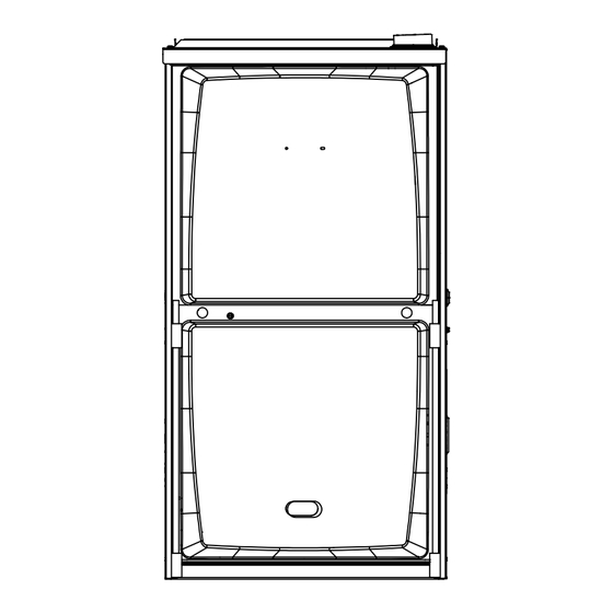
Page 2: Unit Dimensions
(Either Side) (Either Side) 9−1/8 (232) Right 9 (229) 6−9/16 (167) Left 6−7/16 (163) Either Side Either Side Supply Supply 19−1/4 (489) (19) (19) (19) FRONT VIEW SIDE VIEW Model No. 95AF2DF045V12B 95AF2DF070V16B 17−1/2 16−3/8 95AF2DF090V20C 19−7/8 19−1/2 95AF2DF110V20C Page 2... -
Page 3: Parts Arrangement
95AF2DFV Parts Arrangement 95AF2DFV PARTS IDENTIFICATION CONTROL BOX (Includes integrated control, transformer and door switch) VARIABLE SPEED MOTOR (hidden) BAG ASSEMBLY (shipping location) COMBUSTION AIR INDUCER BLOWER DECK DuralokPlus HEAT EXCHANGER ASSEMBLY COLD END HEADER BOX COMBUSTION AIR INDUCER PRESSURE SWITCH PRIMARY LIMIT BURNER BOX ASSEMBLY (includes sensor, rollout switches and ignitor) -
Page 4: 95Af2Dfv Gas Furnace
95AF2DFV Gas Furnace Shipping and Packing List Package 1 of 1 contains The 95AF2DFV Category IV gas furnace is shipped ready for installation in the upflow or horizontal position. The fur 1 - Assembled 95AF2DFV unit nace is shipped with the bottom panel in place. The bottom 1 - Bag assembly containing the following: panel must be removed if the unit is to be installed in hori... -
Page 5: Use Of Furnace As A Construction Heater
In order to ensure proper unit operation in non-direct vent Heating Unit Installed Parallell to Air Handler Unit applications, combustion and ventilation air supply must be provided according to the current National Fuel Gas Code or CSA‐B149 standard. Installation Locations This furnace is CSA International certified for installation clearances to combustible material as listed on the unit AIR HANDLER... -
Page 6: General
The input rate and temperature rise must be set per the WARNING furnace rating plate. One hundred percent (100%) outdoor air must be pro Insufficient combustion air can cause headaches, vided for combustion air requirements during construc nausea, dizziness or asphyxiation. It will also cause tion. - Page 7 confined space such as a closet or small equipment room. CAUTION Even a small leak around the base of the unit at the platform or at the return air duct connection can cause a potentially Do not install the furnace in a corrosive or contami dangerous negative pressure condition.
- Page 8 EQUIPMENT IN CONFINED SPACE - ALL AIR FROM OUTSIDE EQUIPMENT IN CONFINED SPACE (Inlet Air from Crawl Space and Outlet Air to Outside) (Inlet Air from Ventilated Crawlspace and Outlet Air to Outside) VENTILATION LOUVERS (Each end of attic) ROOF TERMINATED EXHAUST PIPE Roof Terminated Exhaust Pipe...
- Page 9 95AF2 Furnaces with EQUIPMENT IN CONFINED SPACE - ALL AIR FROM OUTSIDE (All Air Through Ventilated Attic) 1/2 HP Blower Motor ROOF TERMINATED VENTILATION LOUVERS EXHAUST PIPE (Each end of attic) RIGID LEG (Remove shipping bolt OUTLET and washer) FIGURE 11 INLET AIR SIDE WALL FURNACE...
-
Page 10: Setting Equipment
SETTING EQUIPMENT AIR FLOW AIR FLOW AIR FLOW UNIT UNIT FRONT FRONT 1/2” max. SIDE VIEW SIDE VIEW FRONT VIEW Unit must be level side-to-side. Unit may be positioned from level to 1/2” toward the front to aid in draining. FIGURE 12 Horizontal Front... - Page 11 Installation on Non-Combustible Flooring Figure 15 WARNING 1 - Cut floor opening keeping in mind clearances listed on Improper installation of the furnace can result in per unit rating plate. Also keep in mind gas supply connec sonal injury or death. Combustion and flue products tions, electrical supply, flue and air intake connections must never be allowed to enter the return air system and sufficient installation and servicing clearances.
- Page 12 TABLE 2 COMBUSTIBLE FLOORING BASE OPENING SIZE Front to Rear Side to Side Cabinet Catalog FURNACE Width Number B Cabinet 11M60 18 - 3/4 (17.5”) C Cabinet COOLING COIL 11M61 22 - 3/4 (21”) PROPERLY SIZED FLOOR OPENING PLENUM FURNACE SUPPLY AIR PLENUM PROPERLY...
-
Page 13: Filters
Filters Supply Air Plenum If the furnace is installed without a cooling coil, a removable This unit is not equipped with a filter or rack. A field-pro access panel should be installed in the supply air duct. The vided high velocity rated filter is required for the unit to oper access panel should be large enough to permit inspection ate properly. - Page 14 CAUTION IMPORTANT Solvent cements for plastic pipe are flammable liq 95AF2DFV exhaust and intake connections are uids and should be kept away from all sources of made of PVC. Use PVC primer and solvent cement ignition. Do not use excessive amounts of solvent when using PVC vent pipe.
- Page 15 TABLE 5 OUTDOOR TERMINATION USAGE* STANDARD CONCENTRIC Flush Wall Kit Wall Ring Kit 1-1/2 inch 2 inch 3 inch Mount Vent 2 inch 3 inch 2 inch Pipe Input Size Field 51W11 Dia. in. 71M80 69M29 Fabricated 44J40 (US) 22G44 (US) (US) (US) 60L46 (US)
-
Page 16: Joint Cement Procedure
Joint Cementing Procedure Venting Practices All cementing of joints should be done according to the Piping Suspension Guidelines specifications outlined in ASTM D 2855. NOTE - A sheet metal screw may be used to secure the SCHEDULE 40 intake pipe to the connector, if desired. Use a drill or PVC - 5' self tapping screw to make a pilot hole. - Page 17 2 - When furnace is installed in a residence where unit is venting system. Turn on any exhaust fans, such as shut down for an extended period of time, such as a range hoods and bathroom exhausts, so they will oper vacation home, make provisions for draining conden...
- Page 18 Vent Piping Guidelines Use the following steps to correctly size vent pipe diameter. The 95AF2DFV can be installed as either a Non-Direct Vent or a Direct Vent gas central furnace. NOTE - In Non‐Direct Vent installations, combustion air is taken from indoors or ventilated attic or crawlspace and Piping Size Process flue gases are discharged outdoors.
- Page 19 TABLE 7 Maximum Allowable Intake or Exhaust Vent Length Size intake and exhaust pipe length separately. Values in table are for Intake OR Exhaust, not combined total. Intake and Exhaust must be same pipe size. NOTE - Additional vent pipe and elbows used to terminate the vent pipe outside the structure must be included in the total vent length calculation. Standard Termination at Elevation 0 - 4500 ft 2”...
- Page 20 TABLE 8 Maximum Allowable Exhaust Vent Length Using Ventilated Attic or Crawl Space For Intake Air in Feet NOTE - Additional vent pipe and elbows used to terminate the vent pipe outside the structure must be included in the total vent length calculation. Standard Termination at Elevation 0 - 10,000 ft Number Of 2”...
- Page 21 TYPICAL EXHAUST PIPE CONNECTIONS Pipe size determined in table 7. 2” 2” 2” 2” 2” 3” TRANSITION INTAKE EXHAUST *2” DO NOT transition from smaller to larger pipe size in horizontal TOP VIEW runs of exhaust pipe. * When transitioning up in pipe size, use the shortest length of 2” PVC pipe possible. NOTE −...
- Page 22 Intake Piping EQUIPMENT IN CONFINED SPACE The 95AF2DFV furnace may be installed in either direct (Inlet Air from Ventilated Crawlspace and Outlet Air to Outside) vent or non-direct vent applications. In non-direct vent applications, when intake air will be drawn into the furnace from the surrounding space, the indoor air quality must be Roof Terminated considered.
- Page 23 doors. The 95AF2DFV is then classified as a direct vent, TYPICAL AIR INTAKE PIPE CONNECTIONS Category IV gas furnace. NON−DIRECT VENT APPLICATIONS In both Non‐Direct Vent and Direct Vent applications, the vent termination is limited by local building codes. In the ab INTAKE sence of local codes, refer to the current National Fuel Gas SCREEN...
- Page 24 TABLE 9 Maximum Allowable Exhaust Vent Pipe Length Without Insulation In Unconditioned Space For Winter Design Temperatures Two - Stage High Efficiency Furnace Unit Input Size Winter Design Vent Pipe Temperatures °F (°C) Diameter 2 in. 32 to 21 (0 to -6) 2-1/2 in.
- Page 25 VENT TERMINATION CLEARANCES FOR NON-DIRECT VENT INSTALLATIONS IN THE USA AND CANADA INSIDE CORNER DETAIL Fixed Operable Fixed Closed Closed Operable AREA WHERE TERMINAL AIR SUPPLY INLET VENT TERMINAL IS NOT PERMITTED US Installations Canadian Installations Clearance above grade, veranda, 12 inches (305mm) or 12 in.
- Page 26 VENT TERMINATION CLEARANCES FOR DIRECT VENT INSTALLATIONS IN THE USA AND CANADA INSIDE CORNER DETAIL Fixed Operable Fixed Closed Closed Operable AREA WHERE TERMINAL AIR SUPPLY INLET VENT TERMINAL IS NOT PERMITTED US Installations Canadian Installations Clearance above grade, veranda, 12 inches (305mm) or 12 in.
- Page 27 Details of Intake and Exhaust Piping Terminations for 6 - On field supplied terminations, a minimum distance between the end of the exhaust pipe and the end of the Direct Vent Installations intake pipe without a termination elbow is 8” and a NOTE - In Direct Vent installations, combustion air is taken minimum distance of 6”...
- Page 28 7 - If intake and exhaust piping must be run up a side wall sized per table 10.The intake piping may be equipped to position above snow accumulation or other ob with a 90° elbow turndown. Using turndown will add 5 structions, piping must be supported.
- Page 29 FIELD FABRICATED WALL TERMINATION NOTE − FIELD−PROVIDED REDUCER MAY BE 2” (51mm) 3” (76mm) REQUIRED TO ADAPT LARGER VENT PIPE SIZE Vent Pipe Vent Pipe TO TERMINATION A− Minimum clearance above grade or average 12” (305 mm) 12” (305 mm) snow accumulation B−...
- Page 30 1-1/2” (38mm) accelerator 2” EXTENSION FOR FURNACE provided on 71M80 & 44W92 2” PVC PIPE EXHAUST kits for 95AF2DFV045P36B- 1” EXTENSION FOR PIPE & 070P36B 3” PVC PIPE FLASHING GLUE EXHAUST 12” (305mm) END FLUSH INTO (Not Furnished) FURNACE INTAKE Minimum TERMINATION INTAKE...
- Page 31 4 - Distance between exhaust pipe terminations on mul CONDENSATE TRAP AND PLUG LOCATIONS tiple furnaces must meet local codes. SIZE TERMINATION PIPE PER TABLE 12” (305mm) ABOVE AVE. SNOW ACCUMULATION Trap 3” (76mm) OR UNCONDITIONED 2” (51mm) PVC (same on ATTIC SPACE right side) PROVIDE SUPPORT...
- Page 32 Field Provided Drain Components 95AF2DFV with Evaporator Coil Using a Separate Drain Field Provided Vent Elbow 1” min. 2” max. above condensate drain. Barbed Fitting Condensate Tubin Drain Connection Hose Clamp FIGURE 43 Evaporator Drain Line 6 - If unit will be started immediately upon completion of (vent required) installation, prime trap per procedure outlined in Unit Drain...
- Page 33 TRAP / DRAIN ASSEMBLY USING 1/2” PVC OR 3/4” PVC Optional Condensate Drain Connection Adapter 3/4 inch slip X 3/4 inch mpt (not furnished) 90° Street Elbow 3/4 inch PVC (not furnished) Adapter 3/4 inch slip X 3/4 inch mpt (not furnished) Condensate Drain Connection In Unit 1 (25 mm) Min.
-
Page 34: Gas Piping
Gas Piping IMPORTANT Gas supply piping should not allow more than 0.5”W.C. drop in pressure between gas meter and unit. Supply gas Compounds used on threaded joints of gas piping pipe must not be smaller than unit gas connection. must be resistant to the actions of liquified petro leum gases. - Page 35 MANUAL MAIN SHUT-OFF MANUAL VALVE MAIN SHUT-OFF VALVE GROUND GROUND JOINT JOINT UNION UNION DRIP LEG Left Side Piping Gas Valve Gas Valve (Standard) Right Side Piping (Alternate) DRIP LEG FIELD FIELD NOTE - BLACK IRON PIPE ONLY TO PROVIDED PROVIDED BE ROUTED INSIDE OF CABINET AND INSTALLED...
-
Page 36: Electrical
Electrical Refer to figure 55 for unit wiring. The power supply wiring must meet Class I restric ELECTROSTATIC DISCHARGE (ESD) tions. Protected by either a fuse or circuit breaker, se Precautions and Procedures lect circuit protection and wire size according to unit CAUTION nameplate. - Page 37 One line voltage “HUM” 1/4” spade terminal is pro The furnace integrated control requires both correct vided on the furnace integrated control. Any humidifier polarity and proper ground. Both polarity and proper rated up to one amp can be connected to this terminal grounding should be checked before attempting to op...
- Page 38 W1 on the integrated control must be connected to W1 on Active Dehumidification the thermostat. To achieve additional dehumidification, clip the jumper wire located below the DEHUM terminal on the integrated ignition/ blower control board and connect a humidity con Automatic Heat Staging trol that opens on humidity rise to the DEHUM and R termi...
- Page 39 95AF2DFV Schematic Wiring Diagram FIGURE 55 Page 39...
-
Page 40: Integrated Control
Integrated Control Troubleshooting Make the following visual checks before troubleshooting: 1. Check to see that the power to the furnace and the inte grated ignition/blower control is ON. 2. The manual shutoff valves in the gas line to the furnace must be open. -
Page 41: Unit Start-Up
Unit Start-Up 5 - Wait for the combustion air inducer to stop. Set the thermostat to initiate a heating demand and again al FOR YOUR SAFETY READ BEFORE OPERATING low the burners to fire for approximately 3 minutes. 6 - Adjust the thermostat to deactivate the heating de WARNING mand and wait for the combustion air inducer to stop. -
Page 42: Gas Pressure Adjustment
4 - Move gas valve switch to OFF. Furnace should operate at least 5 minutes before checking gas flow. Determine time in seconds for two revolutions of 5 - Replace the access panel. gas through the meter. (Two revolutions assures a more Failure To Operate accurate time.) Divide by two and compare to time in table If the unit fails to operate, check the following:... -
Page 43: Proper Combustion
Proper Combustion High Altitude Furnace should operate minimum 15 minutes with correct NOTE - In Canada, certification for installations at eleva manifold pressure and gas flow rate before checking com tions over 4500 feet (1372 m) is the jurisdiction of local au bustion. - Page 44 Testing for Proper Venting and Sufficient Combustion Air for Non-Direct Vent Applicaitons horizontal pitch. Determine there is no blockage or re WARNING striction, leakage, corrosion, or other deficiencies which could cause an unsafe condition. CARBON MONOXIDE POISONING HAZARD! 3 - To the extent that it is practical, close all building doors Failure to follow the steps outlined below for each and windows and all doors between the space in appliance connected to the venting system being...
-
Page 45: Other Unit Adjustments
Other Unit Adjustments The igniter energizes and is allowed to warm up for 20 sec onds before the gas valve energizes on 1st stage and burn Primary Limit. ers ignite. 45 seconds after the control confirms ignition The primary limit is located on the heating compartment has occurred, the control drops the combustion blower to vestibule panel. -
Page 46: Service
Verify that the unit is operating at the desired speed and WARNING within the rise range as shown on the unit rating plate. The correct replacement motor must be installed as The system must not be in either the passive or ac soon as possible to ensure continued satisfactory op... - Page 47 Winterizing and Condensate Trap Care 19 - Remove screws along vestibule sides which secure 1 - Turn off power to the furnace. vestibule panel and heat exchanger assembly to cabi net. Remove two screws from blower rail which secure 2 - Have a shallow pan ready to empty condensate water. top heat exchanger flange.
-
Page 48: Planned Service
Cleaning the Burner Assembly (if needed) Blower access door - Must be properly in place and pro 1 - Turn off electrical and gas power supplies to furnace. vide a seal between the return air and the room where the Remove upper and lower furnace access panels. -
Page 49: Start Up And Performance Check List
Start-Up and Performance Check List UNIT SET UP Upflow Furnace shown in Typical Set Up Furnace Model Number_______________ Serial Number_________________ SUPPLY Line Voltage GAS SUPPLY LP Propane Gas Natural Gas Piping Connections Tight Leak Tested Flter Supply Line Pressure “W.C.________ RETURN AIR Gas Supply Pressure DUCT SYS... - Page 50 UNIT OPERATION HEATING MODE COOLING MODE GAS MANIFOLD PRESSURE “W.C._____ INDOOR BLOWER AMPS______ COMBUSTION SAMPLE CO CO PPM_______ TEMPERATURE DROP ______ Return Duct Temperature _________ INDOOR BLOWER Supply Duct Temperature _______ AMPS______ Temperature Drop = _________ TEMPERATURE RISE TOTAL EXTERNAL STATIC (dry coil) Supply Duct Temperature ________ Supply External Static _______ Return Duct Temperature...
- Page 51 Requirements for Commonwealth of Massachusetts Modifications to NFPA-54, Chapter 10 4 - INSPECTION. The state or local gas inspector of the side wall, horizontally vented, gas-fueled equipment Revise NFPA-54 section 10.8.3 to add the following re shall not approve the installation unless, upon inspec quirements: tion, the inspector observes carbon monoxide detec...
- Page 52 FOR THE PROVINCE OF ONTARIO, HORIZONTAL SIDEWALL VENT APPLICATIONS ONLY For exterior horizontal venting applications, the 2” X 1.5” plume is unobjectionable. If the installation requires more reducer for 2” venting at the point where the exhaust pipe separation between the flue gases and the building struc exits the structure is not required in direct or nondirect vent ture, a reducer may be installed on the exhaust pipe to in...
Need help?
Do you have a question about the 95AF2DF045V12B and is the answer not in the manual?
Questions and answers