Table of Contents
Advertisement
This manual must be left with the homeowner for future reference.
This is a safety alert symbol and should never be ignored. When you see this symbol on labels or in
manuals, be alert to the potential for personal injury or death.
CAUTION
As with any mechanical equipment, personal injury
can result from contact with sharp sheet metal
edges. Be careful when you handle this equipment.
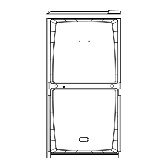
Unit Dimensions
. . . . . . . . . . . . . . . . . . . . . . . . . . . . . . . .
. . . . . . . . . . . . . . . . . . . . . . . . . . . . . . .
. . . . . . . . . . . . . . . . . . . . . . . . . . . . . . . . . . . . . . . .
. . . . . . . . . . . . . . . . . . . . . . . . . . . . . . .
. . . . . . . . . . . . . . . . . . . . . . . . . . . . . . . . . . . . . . . . . .
. . . . . . . . . . . . . . . . . . . . . . . . . . . . . . . . . . . .
02/11 Supersedes 01/11
02/11
*2P0211*
P.O. Box 799900, Dallas, TX 75379−9900
INSTALLATION INSTRUCTIONS
92AF1DF and 95AF1DF
Counterflow Warm Air Gas Furnaces
TABLE OF CONTENTS
. . . . . . . . . . . .
. . . . . . . . . . . . . . . . .
. . . . . . . . . . . . . . . . . . . . . . . .
. . . . . . . . . . .
. . . . . . . . . . . .
. . . . . . . . . . . . . . . . . . .
. . . . . . . . . . . . . . . . . . . . . . .
Page 1
Improper installation, adjustment, alteration, service
or maintenance can cause property damage, person-
al injury or loss of life. Installation and service must
be performed by a licensed professional installer (or
equivalent), service agency or the gas supplier.
2
. . . . . . . . . . . . . . . . . . . . . . . . . . . . . . . .
3
. . . . . . . . . . . . . . . . . . . . . . . . . . . . . . . . . . . . .
4
. . . . . . . . . . . . . . . . . . . . . . . . . . . . . . . . . . . . . . .
4
. . . . . . . . . . . . . . . . . . . . . . . . . . . . . . . . . . . .
4
Gas Pressure Measurement
5
. . . . . . . . . . . . . . . . . . . . . . . . . . . . . . . . . . . .
6
Testing Non Direct Appliances for Proper Air
6
9
. . . . . . . . . . . . . . . . . . . . . . . . . . . . . . . . . . . . . . . .
12
. . . . . . . . . . . . . . . . . . . . . . . . . . . . . . . .
12
12
. . . . . . . . . . . . . . . . . . . . . . . . . . . . . . . .
14
Start Up Checklist
. . . . . . . . . . . . . . . . . . . . . . . . . . . . . . .
WARNING
. . . . . . . . . . . . . . . . . . . . . . . . . . .
. . . . . . . . . . . . . . . . . . . . . .
. . . . . . . . . . . . . . . . . . . . . . . . . . . . . .
. . . . . . . . . . . . . . . . . . . . . . . . . .
. . . . . . . . . . . . . . .
506721−01
*P506721-01*
14
15
30
32
36
38
38
38
. . . . . . . .
39
40
41
43
43
44
45
Advertisement
Table of Contents

Related Manuals for Aire-Flo 92AF1DF


Summary of Contents for Aire-Flo 92AF1DF
-
Page 1: Table Of Contents
P.O. Box 799900, Dallas, TX 75379−9900 INSTALLATION INSTRUCTIONS 92AF1DF and 95AF1DF Counterflow Warm Air Gas Furnaces This manual must be left with the homeowner for future reference. This is a safety alert symbol and should never be ignored. When you see this symbol on labels or in manuals, be alert to the potential for personal injury or death. - Page 2 92AF1DF/95AF1DF Unit Dimension − inches (mm) 9/16 (14) COMBUSTION AIR INTAKE RETURN AIR OPENING EXHAUST AIR OUTLET 2−1/16 (52) 9/16 2−1/4 (14) (57) (127) TOP VIEW 3/4 (19) 27−3/4 (705) Front Panel 9/16 19−7/16 9/16 (14) (494) (14) FLOW ELECTRICAL INLET...
-
Page 3: 92Af1Df/95Af1Df Parts Arrangement
92AF1DF/95AF1DF Parts Arrangement CONTROL BOX (Includes integrated control, transformer and door switch) BAG ASSEMBLY BLOWER MOTOR (hidden) BLOWER ACCESS PANEL COMBUSTION AIR INDUCER BLOWER DECK PRIMARY LIMIT COLD END HEADER BOX HEAT EXCHANGER GAS VALVE BURNER ACCESS PANEL BURNER BOX ASSEMBLY... -
Page 4: 92Af1Df/95Af1Df Gas Furnace
LP applications. The 92AF1DF and 95AF1DF can be installed as a Direct Check equipment for shipping damage. If you find any Vent or Non−Direct Vent gas central furnace. -
Page 5: Use Of Furnace As Construction Heater
Air Flow to do so may cause erratic limit operation and premature heat exchanger failure. This 92AF1DF/95AF1DF furnace must be installed so that its electrical components are protected from water. FIGURE 3 NOTE − This furnace is designed for a minimum continu- Installation in Combination with a Cooling Coil ous return air temperature of 60°F (16°C) or an intermit-... - Page 6 • The input rate and temperature rise must be set per the confined space with air from outside. furnace rating plate. • The furnace heat exchanger, components, duct system, • One hundred percent (100%) outdoor air must be pro- air filters and evaporator coils must be thoroughly vided for combustion air requirements during construc- cleaned following final construction clean−up.
-
Page 7: General
In the absence of local codes concerning air for combus− ifornia to cause cancer.) tion and ventilation, use the guidelines and procedures in this section to install 92AF1DF/95AF1DF furnaces to en- Fiberglass wool may also cause respiratory, skin, sure efficient and safe operation. You must consider and eye irritation. - Page 8 All gas-fired appliances require air for the combustion pro- dangerous negative pressure condition. Air for combustion cess. If sufficient combustion air is not available, the fur- and ventilation can be brought into the confined space ei- nace or other appliance will operate inefficiently and un- ther from inside the building or from outside.
- Page 9 EQUIPMENT IN CONFINED SPACE − ALL AIR FROM OUTSIDE EQUIPMENT IN CONFINED SPACE − ALL AIR FROM OUTSIDE (Inlet Air from Crawl Space and Outlet Air to Ventilated Attic) (All Air Through Ventilated Attic) VENTILATION LOUVERS (Each end of attic) ROOF TERMINATED VENTILATION LOUVERS ROOF TERMINATED...
-
Page 10: Setting Equipment
Allow for clearances to combustible materials as indicated 92AF1DF090P16C on the unit nameplate. Minimum clearances for closet or al- RIGID LEG remove shipping bolt and washer cove installations are shown in figure 11. WARNING Blower access panel must be securely in place when blower and burners are operating. - Page 11 Installation on Non−Combustible Flooring (Figure 12) WARNING 1 − Cut floor opening keeping in mind clearances listed on Improper installation of the furnace can result in per- unit rating plate. Also keep in mind gas supply connec- sonal injury or death. Combustion and flue products tions, electrical supply, flue and air intake connections must never be allowed to enter the return air system and sufficient installation and servicing clearances.
- Page 12 TABLE 2 COMBUSTIBLE FLOORING BASE OPENING SIZE Front to Rear Side to Side Cabinet Catalog FURNACE Width Number B Cabinet 11M60 18 − 3/4 (17.5") C Cabinet COOLING COIL 11M61 22 − 3/4 (21") PROPERLY SIZED FLOOR OPENING PLENUM FURNACE SUPPLY AIR PLENUM PROPERLY...
-
Page 13: Filters
Filters Pipe & Fittings Specifications All pipe, fittings, primer and solvent cement must conform This unit is not equipped with a filter or rack. A field−pro- with American National Standard Institute and the Ameri- vided filter is required for the unit to operate properly. Table can Society for Testing and Materials (ANSI/ASTM) stan- 3 lists recommended filter size. - Page 14 Metal or plastic strapping may be used for vent pipe hangers. Uniformly apply a liberal coat of PVC 92AF1DF/95AF1DF exhaust and intake connections primer for PVC or use a clean dry cloth for ABS to clean in- are made of PVC. Use PVC primer and solvent ce- side socket surface of fitting and male end of pipe to depth ment when using PVC vent pipe.
-
Page 15: Joint Cementing Procedure
Hammer blows should not be used when inserting pipe. If a 92AF1DF/95AF1DF furnace replaces a furnace which 8 − After assembly, wipe excess cement from pipe at end was commonly vented with another gas appliance, the size of the existing vent pipe for that gas appliance must be of fitting socket. -
Page 16: Vent Piping Guidelines
How many? Vent Pipe Guidelines The 92AF1DF/95AF1DF can be installed as either a Non− Direct Vent or a Direct Vent gas central furnace. NOTE − In Non-Direct Vent installations, combustion air is Desired pipe size? 2", 2−1/2"... - Page 17 TABLE 7 Maximum Allowable Intake or Exhaust Vent Length in Feet *Size intake and exhaust pipe length separately. Values in table are for Intake OR Exhaust, not combined total. Both Intake and Exhaust must be same pipe size. Standard Termination at Elevation 0 − 10,000 ft. 2"...
- Page 18 TYPICAL EXHAUST PIPE CONNECTIONS Pipe size determined in table 7. 2” 2” 2” 2” 2” 3” TRANSITION INTAKE DO NOT transition from smaller EXHAUST *2” to larger pipe size in horizontal TOP VIEW runs of exhaust pipe. * When transitioning up in pipe size, use the shortest length of 2” PVC pipe possible. NOTE −...
- Page 19 Dilution and Ventilation Air section must be followed. doors. The 92AF1DF/95AF1DF is then classified as a di- Follow the next two steps when installing the unit in Direct rect vent, Category IV gas furnace.
- Page 20 VENT TERMINATION CLEARANCES FOR NON−DIRECT VENT INSTALLATIONS IN THE USA AND CANADA INSIDE CORNER DETAIL Fixed Operable Fixed Closed Closed Operable AREA WHERE TERMINAL AIR SUPPLY INLET VENT TERMINAL IS NOT PERMITTED US Installations Canadian Installations Clearance above grade, veranda, 12 inches (305mm) or 12 in.
-
Page 21: Vent Termination Clearances
VENT TERMINATION CLEARANCES FOR DIRECT VENT INSTALLATIONS IN THE USA AND CANADA INSIDE CORNER DETAIL Fixed Operable Fixed Closed Closed Operable AREA WHERE TERMINAL AIR SUPPLY INLET VENT TERMINAL IS NOT PERMITTED US Installations Canadian Installations Clearance above grade, veranda, 12 inches (305mm) or 12 in. - Page 22 Details of Intake and Exhaust Piping Terminations for between the end of the exhaust pipe and the end of the intake pipe without a termination elbow is 8" and a Direct Vent Installations minimum distance of 6" with a termination elbow. See NOTE −...
- Page 23 Intake Front View of Intake and Exhaust Exhaust Intake Exhaust TABLE 9 2" (51mm) 3" (76mm) Vent Pipe Vent Pipe A− Clearance above grade or average snow 12" (508MM) Min. 12" (508MM) Min. accumulation 12" B−Horizontal 6" (152MM) Min. 6" (152MM) Min. separation between 24"...
- Page 24 FIELD−SUPPLIED WALL TERMINATION OR FIELD−SUPPLIED WALL TERMINATION OR (15F74) WALL RING TERMINATION KIT (15F74) WALL RING TERMINATION KIT WITH INTAKE ELBOW NOTE − FIELD PROVIDED NOTE − FIELD PROVIDED REDUCER MAY BE REDUCER MAY BE 1/2" (13mm) ARMAFLEX 1/2" (13mm) ARMAFLEX REQUIRED TO ADAPT REQUIRED TO ADAPT INSULATION IN UN-...
- Page 25 1−1/2" (38mm) accelerator EXHAUST VENT Front View provided in 71M80 & 44W92 kits for 045 & 070 units SIZE TERMINATION PIPE PER INTAKE FLASHING TABLE 8. 12” (305mm) (Not Furnished) INTAKE Minimum Above Average Snow Accumulation Top View 1/2" (13mm) Foam Insulation in Unconditioned Space SHEET METAL STRAP (Clamp and sheet metal strap...
- Page 26 WALL TERMINATION KITS (CLOSE−COUPLE) EXTENDED VENT FOR GRADE CLEARANCE 2 inch (51 mm) 22G44 (US) 3 inch (76 mm) 44J40 (US) If intake and exhaust pipe is less than 12 in. (305 mm) above snow accumulation or other obstructions, field− fabricated piping must be installed.
- Page 27 92AF1DF/95AF1DF DIRECT VENT APPLICATION SIZE TERMINATION USING EXISTING CHIMNEY PIPE PER TABLE 8. 12" (305mm) STRAIGHT−CUT OR ANGLE−CUT IN DIRECTION ABOVE AVE. OF ROOF SLOPE * SNOW 1/2" (13mm) FOAM ACCUMULATION INSULATION 8" − 12" 3" − 8" EXHAUST VENT (76mm−...
- Page 28 1−1/2 in. (same on left NON−DIRECT VENT FIELD SUPPLIED WALL TERMINATION EX- side) TENDED OR (15F74) WALL TERMINATION VENT PIPE EXTENDED FIGURE 40 92AF1DF/95AF1DF NON−DIRECT VENT APPLICATION USING EXISTING CHIMNEY SIZE TERMINATION STRAIGHT−CUT OR ANGLE−CUT IN DIRECTION PIPE PER TABLE 8.
- Page 29 5 − If unit will be started immediately upon completion of 92AF1DF/95AF1DF with Evaporator Coil installation, prime trap per procedure outlined in Unit Start−Up section. Condensate line must slope downward away from the Condensate trap and Field−Provided Vent trap to drain. If drain level is above condensate trap, evaporator coil must drain separately as shown.
- Page 30 TRAP / DRAIN ASSEMBLY USING 1/2" PVC OR 3/4" PVC OPTIONAL Condensate Drain Connection Adapter 1/2 inch slip X Adapter 1/2 inch slip X 1/2 inch mpt (Not Furnished) Condensate Drain 1/2 inch mpt (Not Furnished) Connection In Unit Vent 90°...
-
Page 31: Gas Piping
Gas Piping 4 − Piping should be sloped 1/4 inch per 15 feet (6mm per 5.6m) upward toward the gas meter from the furnace. The piping must be supported at proper intervals, ev- ery 8 to 10 feet (2.44 to 3.05m), using suitable hangers CAUTION or straps. - Page 32 Right Side Piping Left−Side Piping (Alternate) (Standard) MANUAL AUTOMATIC MAIN SHUT−OFF GAS VALVE MANUAL VALVE AUTOMATIC (with manual MAIN SHUT−OFF (With 1/8 in. NPT Plug GAS VALVE shut−off valve) VALVE Plugged Tap (with manual Plug (With 1/8 in. NPT Shown) shut−off valve) Plugged Tap Shown) GROUND...
-
Page 33: Electrical
Removal of the Furnace from Common Vent 4 − Follow the lighting instructions. Turn on the appliance that is being inspected. Adjust the thermostat so that In the event that an existing furnace is removed from a the appliance operates continuously. venting system commonly run with separate gas ap- 5 −... - Page 34 CABINET C22.1) for Canada. A green ground wire is provided in the field make−up box. NOTE − The 92AF1DF/95AF1DF furnace contains elec- tronic components that are polarity sensitive. Make sure that the furnace is wired correctly and is properly grounded.
- Page 35 CONDENSING UNIT COOLING 2 − When the 92AF1DF/95AF1DF is running in the heat- ing mode, the indoor blower will run on the heating INDOOR BLOWER CONDENSING speed. The heat off delay is adjustable with a default...
- Page 36 TYPICAL 92AF1DF/95AF1DF WIRING DIAGRAM FIGURE 53 Page 36...
-
Page 37: Unit Start Up
CAUTION The gas valve on the 92AF1DF/95AF1DF is equipped with a gas control switch. Use only your hand to move switch. Never use tools. If the switch will not move by Before attempting to perform any service or mainte- nance, turn the electrical power to unit OFF at dis- hand, do not try to repair it. - Page 38 Placing the furnace into operation: MANIFOLD MANIFOLD PRESSURE 92AF1DF/95AF1DF units are equipped with an automat- PRESSURE ADJUSTMENT ic hot surface ignition system. Do not attempt to manually OUTLET SCREW light burners on this furnace. Each time the thermostat calls for heat, the burners will automatically light. The ig- nitor does not get hot when there is no call for heat on these units.
-
Page 39: Proper Combustion
4500 feet (1372 m) is the jurisdiction of local au- thorities. Supply Model Manifold Pressure in.wg. 92AF1DF/95AF1DF units require no manifold pressure ad- Fuel Input Sizes Pressure in.wg. Min. Max. justments for operation at altitudes up to 10,000 feet (3048 m) above sea level. -
Page 40: High Altitude
92AF1DF/95AF1DF as well as to other gas- 7 − Use the flame of match or candle to test for spillage of fired appliances which are separately vented. -
Page 41: Other Unit Adjustments
Other Unit Adjustments HEAT FAN-OFF TIME IN SECONDS Primary Limit The primary limit is located on the heating compartment vestibule panel. This limit is factory set and requires no ad- justment. NO JUMPER Flame Rollout Switches (Two) To adjust fan−off timing, reposition jumper across pins to achieve desired setting. -
Page 42: Service
Service 3 − Remove the clean out cap from the condensate trap and empty water. Inspect the trap then reinstall the drain plug. WARNING Cleaning Heat Exchanger If cleaning the heat exchanger becomes necessary, follow ELECTRICAL SHOCK, FIRE, the below procedures and refer to figure 1 when disassem- OR EXPLOSION HAZARD. - Page 43 19 − Reinstall heat exchanger into cabinet making sure that 38 − Follow lighting instructions to light and operate fur- the clamshells of the heat exchanger assembly are nace for 5 minutes to ensure that heat exchanger is resting on the support located at the rear of the cabi- clean and dry and that furnace is operating properly.
-
Page 44: Planned Service
Planned Service Integrated Control Diagnostic Codes A service technician should check the following items dur- DIAGNOSTIC CODES ing an annual inspection. Power to the unit must be shut off LED Status DESCRIPTION for safety. No power to control or control harware LED Off Fresh air grilles and louvers (on the unit and in the room fault detected. -
Page 45: Repair Parts List
Repair Parts List The following repair parts are available. When ordering, include the complete furnace model number listed on the CSA nameplate −− Example: 92AF1DF090P16C. All service must be performed by a licensed professional installer (or equivalent), service agency, or gas supplier. Cabinet Parts Heating Parts Upper access panel... - Page 46 Start−Up & Performance Checklist UNIT SET UP (Typical) Furnace: Model Number_______________ Serial Number_________________ SUPPLY Line Voltage Upflow Furnace Shown GAS SUPPLY LP Propane Gas Natural Gas Piping Connections Tight Leak Tested Flter Supply Line Pressure W.C.________ RETURN AIR Gas Supply Pressure DUCT SYSTEM SUPPLY AIR DUCT Sealed...
- Page 47 UNIT OPERATION HEATING MODE (Typical) COOLING MODE GAS MANIFOLD PRESSURE W.C._____ INDOOR BLOWER AMPS______ COMBUSTION SAMPLE CO CO PPM_______ TEMPERATURE DROP ______ Return Duct Temperature _________ INDOOR BLOWER AMPS______ Supply Duct Temperature _______ Temperature Drop = _________ TEMPERATURE RISE TOTAL EXTERNAL STATIC (dry coil) Supply Duct Temperature ________ Supply External Static _______ Return Duct Temperature...
- Page 48 Requirements for Commonwealth of Massachusetts Modifications to NFPA−54, Chapter 10 4 − INSPECTION. The state or local gas inspector of the side wall, horizontally vented, gas−fueled equipment Revise NFPA−54 section 10.8.3 to add the following re- shall not approve the installation unless, upon inspec- quirements: tion, the inspector observes carbon monoxide detec- For all side wall, horizontally vented, gas−fueled equipment...
Need help?
Do you have a question about the 92AF1DF and is the answer not in the manual?
Questions and answers