
Related Manuals for Lanair MX SERIES 250


Summary of Contents for Lanair MX SERIES 250
- Page 1 ® MX SERIES 250 MX SERIES 300 WASTE OIL HEATER Installation and Operating Instructions Lanair Products LLC 4109 Capital Circle Janesville, Wisconsin 53546 1-888-370-6531 www.lanair.com...
- Page 2 Check each component for visible damage. If you find a damaged component, contact a Lanair Service Representative for a replacement. Do not install broken or damaged parts. This heater is designed to provide economically and environmentally friendly disposal of waste oil.
- Page 3 Sec.16 Burner Reference Diagram ........... . page 51 Visit our website at: www.lanair.com...
- Page 4 Section 1 - General Specifications & Hazards MX 250-300 Series Burner NOTE: This burner intended for use with MX Series Lanair Waste Oil-Fired Heaters Only Burner Assembly- Description Performance Ratings Mounting Plate Ignitor Transformer Voltage ..... . 115 vac Fuel Line Inlet Cycles .
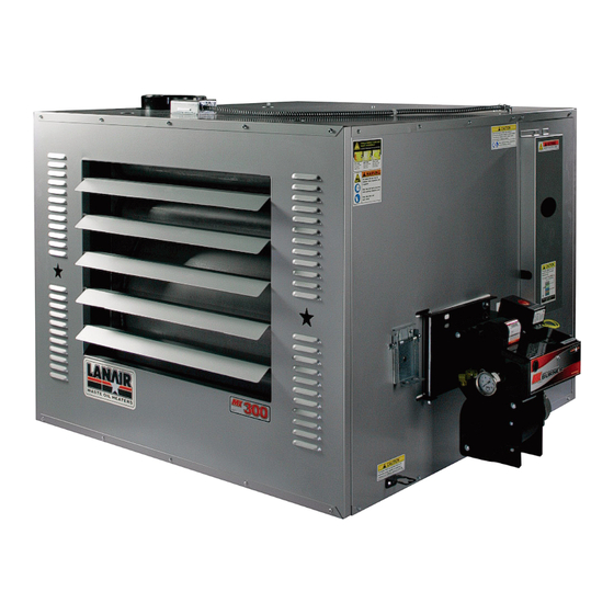
- Page 5 Section 1 - General Specifications & Hazards Description Adjustable Air Flow Louvers Mounting Holes Fan Limit Switch 8" Exhaust Flue Flame View Port Burner Assembly Electrical Connections Cover Secondary Air Filter/Regulator Location Fan Assembly (Internal) Visit our website at: www.lanair.com...
- Page 6 Section 1 - General Specifications & Hazards MX-250/300 FRONT DIMENSIONS: MX-250 Height: 36” Width: 46” Depth: 48” Weight: 630 LBS MX-300 Height: 36” Width: 46” Depth: 48” Weight: 630 LBS FIRING CAPACITIES: MX-250 Nozzle @ 1.79 gallons/hour, No. 2 fuel oil/used crankcase oil MX-300 Nozzle @ 2.14 gallons/hour, No.
- Page 7 Section 1 - General Specifications & Hazards 48” 16” TOP VIEW 6" MX 250-300 8” dia. flue 25” 46” 5.5” 24" 59.5" 9.5" 13.5" RIGHT SIDE MX 250-300 36" LEFT SIDE MX 250-300 36" Visit our website at: www.lanair.com...
- Page 8 Section 1 - General Specifications & Hazards Pump Assembly for use with By-pass Regulator Pump Assembly- Description Pump Platform Performance Ratings Pump Motor Voltage ..... . 115 vac Pump Guard Cycles .
- Page 9 Section 1 - General Specifications & Hazards Optional Metering Pump Assembly Pump Assembly- Description Pump Platform Performance Ratings Pump Motor Voltage ..... . 115 vac Pump Guard Cycles .
- Page 10 This heater is not designed for use in hazardous atmospheres such as: aint Shops, Feed Mills, installations re explosi e or conditions are present or could occur. WARNING! Lanair heaters rely on natural draft. Do drafts (positi e pressures) in the heaters chimney occur in re negati e pressures are created y exhaust fans, (car exhaust, paint s, etc).
-
Page 11: Typical Installation
Section 2 - Heater Install w/ Bypass Regulator TYPICAL INSTALLATION: Chimney Cap HEATER/CHIMNEY PACKAGE 3 ft. taller than any object within 10 ft. Through the roof installation Class “A” Chimney 10 ft. min. Ceiling Hung 8 ft. min. 10 ft. max. Barometric Damper 2-3 ft. - Page 12 Section 2 - Heater Install w/ Metering Pump TYPICAL INSTALLATION: Chimney Cap HEATER/CHIMNEY PACKAGE 3 ft. taller than any object within 10 ft. Through the roof installation Class “A” Chimney 10 ft. min. Ceiling Hung 8 ft. min. 10 ft. max. Barometric Damper 2-3 ft.
-
Page 13: General Requirements
7. Use 3/8” steel threaded rod to suspend the heater from a capable load carrying ceiling structure when not using the Lanair Waste Oil Storage Tank. 8. The heater must be suspended level for proper operation. A heater that is not level could cause a hazardous situation in which personal injury or property damage may result. - Page 14 Section 3 - Chimney/Vent System Chimney Cap NOTE: Class "A" components require a 2" clearance 3 ft. taller than from combustible materials. All other chimney compo- any object within 10 ft. nents require a minimum 18" clearance from com- bustible materials Class “A”...
- Page 15 16. The chimney must be capable of producing a negative -.02 W.C. draft when cold and - .06 W.C. draft when hot. Refer to Section 4 Draft Instructions. Refer to Section 3.10 for typical Chimney Installation. NOTE: Do not install chimney in front of the heater (in air stream of fan) Visit our website at: www.lanair.com...
- Page 16 Section 3 - Chimney/Vent System 17. If you are unable to attain the proper draft, check for exhaust fans in the building. To test if there is a problem, open an overhead door and see if you now have the proper draft. You may have to add one or more sections of “Class A”...
- Page 17 Section 4 - Draft The Lanair heater should have a (negative) -.02 draft reading when cold, and a (negative) -.06 when hot. Check the heater when it is running after 45 minutes. If the reading is not what it should be, adjust the barometric damper according to the instructions provided with the damper.
- Page 18 Section 4 - Draft The Lanair heater should have a (negative) -.02 draft reading when cold, and a (negative) -.06 when hot. Check the heater when it is running after 45 minutes. If the reading is not what it should be, adjust the barometric damper according to the instructions provided with the damper.
- Page 19 Section 5 - Fuel Supply Tank Installation If using a Lanair supply tank follow instructions included with the tank. General Requirements 1. The fuel supply tank and supply lines must be installed in accordance with the National Fire Protection Association requirements, as well as State and Local ordinances.
- Page 20 4. The fuel pump contains an internal strainer that periodically needs to be cleaned. This internal strainer is mounted behind the pump cover. Before removing the pump cover make sure you have a new gasket on hand. Contact the Lanair Customer Service Department for the proper gasket for your model of pump, at 1-888-370-6531.
- Page 21 Section 6 - Fuel Supply Pump/Piping When using a by-pass regulator install the fuel supply line from the fuel by-pass regulator (port B) to the inlet port on the left side of the burner using 1/2” inside diameter (.493) steel pipe, or 1/2” outside diameter copper tubing. The maximum distance of this line is 25 feet.
- Page 22 10. Set the air filter/regulator on the front of the furnace to 18 LBS. See illustration below (Fig. 5) for a typical air pressure supply installation. Figure 5 air inlet secondary air filter/ bottom of burner regulator (included) to primary air filter/regulator (not included) and air supply Visit our website at: www.lanair.com...
- Page 23 Section 8 - Electrical Connections CAUTION: HAZARD OF ELECTRICAL SHOCK! Main Electrical Installation 1. All wiring must comply with the National Electrical Code. State and Local Ordinances, and be wired by a qualified electrician. 2. Electrical service MUST be connected to a separate 20 AMP, 115 VAC, 60 HZ single phase circuit.
- Page 24 Lanair Pump Motor Electrical Connections Provided by Installer Figure 7 Visit our website at: www.lanair.com...
- Page 25 Lanair Metering Pump Electrical Connections Provided by Installer Figure 7 Visit our website at: www.lanair.com...
- Page 26 Section 8 - Electrical Connections CAUTION: HAZARD OF ELECTRICAL SHOCK! Fuel Supply Pump Electrical Installation 1. All wiring must comply with the National Electrical Code, State and Local Ordinances, and be wired by a qualified electrician. 2. The electrical conductors to the fuel pump motor MUST be stranded 14 GA minimum. 3.
- Page 27 The Air Filter/Regulator performs two functions: It removes condensation and dirt from the air. and it controls the amount of air pressure reaching the nozzle and air operated fuel valve. The Air/Filter Regulator is mounted on the cabinet near the burner. Visit our website at: www.lanair.com...
- Page 28 Section 9 - Controls Electric Air Solenoid Valve The Electric Air Solenoid Valve is controlled by the Oil Primary Control. It acts as a shut-off valve, (it’s open during operation, and closed when the burner is off ). The Electric Air Solenoid Valve is located inside of the burner’s electrical box.
- Page 29 Turn the room thermostat below room temperature or “OFF”. The fuel supply pump will now stop. Reconnect the fuel supply line to the burner. Remove the jumper wire from the F-F terminals on the oil primary control, reattach the yellow cad cell wires. Visit our website at: www.lanair.com...
- Page 30 Section 10 - Priming The Fuel Pump 12. Turn the room thermostat below room temperature or “OFF” . The fuel supply pump will now stop. 13. Reconnect the fuel supply line to the burner. 14. Remove the jumper wire from the F-F terminals on the oil primary control, reattach the yellow cad cell wires.
- Page 31 14. Adjust the burner air filter/regulator to 18 PSI, and the primary air regulator to 30 PSI. NOTE: 18 PSI on the air filter/regulator is the starting point, you may need to adjust from there when VISUALLY SETTING THE FLAME (See page 29-31, flame adjustment). Visit our website at: www.lanair.com...
- Page 32 Section 11 - Burner Start-Up Procedure 15. When using the by-pass regulator adjust the fuel pressure gauge on the left side of the burner to read. No. 1 & No. 2 Fuel Oil Approved Waste Oil Model MX-250 2.25 (2-1/4) - 2.5 (2-1/2)LBS. 2.5 (2-1/2) - 2.75 (2-3/4) LBS.
- Page 33 100 percent accurate, VISUAL INSPECTION OF THE FLAME IS REQUIRED in order to properly dial in the flame settings, see page 30. combustion The combustion air baffle is NOT air baffle factory set Visit our website at: www.lanair.com...
- Page 34 Section 12 - Flame Adjustment NOTE: ALWAYS WEAR EYE, FACE AND BREATHING PROTECTION AND PROTECTIVE CLOTHING WHEN INSPECTING OR ADJUSTING FLAME. Lift the inspection port cover on the front of the combustion chamber to observe the flame. The flame tips should extend 3/4 of the way into the combustion chamber. When the unit is adjusted properly the ash inside the chamber will be white to off white.
- Page 35 Bright yellow in color. Flame extends 3/4 into the chamber. Flame is not impinging on the chamber walls. If you need assistance with flame adjustment, please call Lanair's Parts and Service Department. DO NOT OVER FIRE YOUR HEATER. IMMEDIATELY ADJUST THE BURNER TO THE PROPER FLAME LENGTH TO PREVENT DAMAGE TO YOUR HEATER.
- Page 36 Section 13 - Service / Maintenance MX SERIES HEATER SERVICE / MAINTENANCE SCHEDULE DAILY WEEKLY MONTHLY ANNUALLY (Season Shut Down) Check fuel supply Drain water/ anti- Check combustion Shut off main power tank level (pre-strain freeze from the fuel chamber and heat supply to heater.
- Page 37 Section 13 - Service / Maintenance Air Pre-Heater Breakdown This entire pre-heater assembly is available. Part# 9812 (For a Tune-Up) Visit our website at: www.lanair.com...
- Page 38 Section 13 - Service / Maintenance Maintenance - Air Pre-Heater Remove Pre-Heater Assembly Ref. Part Disconnect the air line from the Qty. Description brass fitting on the air pre-heater 9853 turbulator and then from set screw the air solenoid and remove. 9899 nozzle Heater Disconnect wiring from the oil pre-...
- Page 39 Re-attach diaphragm assembly and hand tighten. NOTE: Do not over tighten. 12. Replace Ignitor Assembly (see page 39) 13. Service Oil Pre-Heater (see pages 33-37 for Annual Maintenance Instructions) THE ENTIRE PRE-HEATER ASSEMBLY IS AVAILABLE PART# 9812 Visit our website at: www.lanair.com...
- Page 40 Section 13 - Service / Maintenance Oil Pre-Heater Breakdown Maintenance - Oil Pre-Heater Ref. Part Qty. Description 1. Separate Air Pre-Heater from Oil 8992 cartridge heater Pre-Heater (10) pre-heater face plate Remove o-ring hex cap screw o-ring 13/16" OD 2. Disassemble Oil Pre-Heater 2902 oil block Remove six hex cap screws (3)
- Page 41 Reconnect the air line by connecting the one end of the air line to the air solenoid and the other end to the air fitting (see page 51). 9. Test Operation Follow start-up procedure, page 27. Visit our website at: www.lanair.com...
- Page 42 Section 13 - Service / Maintenance Cleaning Suction Line Strainer bolt The suction line strainer should be cleaned every 30 days of operation. The element is a washable metal element. If your waste oil is extremely dirty, this strainer may need to be cleaned more frequently.
- Page 43 Turbulator 1/4” max. from Adjust as required and secure the end of the tube pre-heater assembly to the burn- er housing by tightening the adjustment screw on the side of the burner housing (see illustra- tion). Visit our website at: www.lanair.com...
- Page 44 Section 13 - Service / Maintenance Air Pre-Heater Diaphragm Breakdown 1. Remove the four hex cap screws from the diaphragm assembly o-ring 2. Disassemble and inspect diaphragm, diaphragm spring and o-ring . 3. Thoroughly clean remaining parts. piston 4. Re-assemble the diaphragm, hex cap o-ring, spring and hex cap screws.
- Page 45 Remove the clean out cover from the heater by removing (16) 1/2 hex head nuts & washers. If more than 1/4” of ash is present clean the heat exchanger tubes. Visit our website at: www.lanair.com...
- Page 46 7. Before replacing the combustion chamber access doors, replace the white gasket seal on the door (contact the Lanair Service Department). When replacing the gaskets apply a light film of gasket adhesive to adhere the new gasket to the door. Lube the threads of the screws with a high temperature lubricant.
- Page 47 Re-assemble using new small plug, spring large plug washer and diaphragm (Kit P/N 9874). spring NOTE: Pay close attention to the posi- tions of the large and small plugs. large plug washer diaphragm body Visit our website at: www.lanair.com...
- Page 48 MX-250 & MXB-250 ..109 ML/MIN MX-300 & MXD-300 ..139 ML/MIN If flow rate using a metering pump is more than +/- 10% contact Lanair Service at 888-370-6531. After repairs are made, remove the cad cell jumper wire, and reconnect the cad cell wires to the oil primary.
- Page 49 . d l e l l Fuel contains gear lubes (use approved fuels only). Reading fluctuates (jumps). Vacuum leaks in the suction side of the piping to the pump. Low fuel level in the tank. Visit our website at: www.lanair.com...
- Page 50 Section 14 - Troubleshooting Burner fuel pressure gauge reading hints: Fuel gauge fluctuates (jumps): Leak in suction line plumbing. Water/Anti-freeze in fuel. Air in fuel, refer to Troubleshooting Chart Item B. Quad ring seal for the nozzle may be damaged. Seal in adapter block may be worn or damaged.
- Page 51 29-31. i t c 9. Improper draft 9. Check draft see page 15. Make sure chimney is properly installed 10. Plugged heat exchanger, 10. Clean heater including or chimney manifold, chimney Visit our website at: www.lanair.com...
- Page 52 Section 14 - Troubleshooting C. Burner fires, and then 1. Contaminated fuel supply 1. Drain and clean fuel fails on oil primary safety (water/anti-freeze/gear lube) supply tank. Clean fuel or dirty fuel filter. filter (see page 38) 2. Improper draft 2.
- Page 53 Lanair Products LLC (Manufacturer) warrants to the original purchaser of this used oil heater, that it will repair or replace at Lanair Products LLC’s option, any part which is in normal use proves to be defective in material or workmanship within a period of one year from the date of purchase, provided same is returned (transportation pre-paid) F.O.B.
- Page 54 CHAMBER AND HEAT EXCHANGER LIMITED WARRANTY Lanair Products LLC, MANUFACTURER, hereby warrants that any part of manufacturer’s product shall be free from defect in material and workmanship under normal use according to the provisions and limitations herein set forth for a period of one (1) year provided same is returned (pre-paid) F.O.B.
- Page 55 Solenoid Snap Disk To Combustion Blower Fuel Supply Pre-Heater Block Pre-Heater Adjustment Screw Pre-Heater Block Supply Oil Pressure Gauge View Port Pre-Heater Switch To Transformer To “F” Terminals To Oil Primary Cad Cell Burner Cover Visit our website at: www.lanair.com...
- Page 56 ® Lanair Products LLC 4109 Capital Circle Janesville, Wisconsin 53546 1-888-370-6531 www.lanair.com Part # 5031 REV. 21a © 2009 Lanair Products LLC Lanair is a registered trademark of Lanair Products LLC 11-16-10...
Need help?
Do you have a question about the MX SERIES 250 and is the answer not in the manual?
Questions and answers