
Related Manuals for Lanair XT-75


Summary of Contents for Lanair XT-75
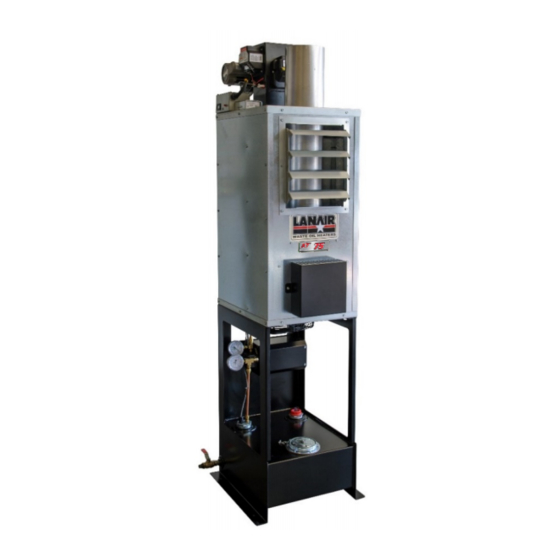
- Page 1 Installation & Operation Manual Multi-Fuel Waste-Oil Heater Model XT 75 115V/60Hz Lanair Products LLC 4109 Capital Circle Item #: 81010044 Rev D Janesville, WI 53546 Issue Date: 23 August 2021 www.lanair.com 1-888-370-6531...
-
Page 3: Before You Begin
• If you have any questions or concerns during the installation or operation of the heater, contact your local service representative or Lanair. Thank you for purchasing a Lanair heater. Record your Unit I.D. number below for future reference. Unit I.D. #:... -
Page 4: Table Of Contents
Table of Contents Before You Begin… ......................... i Safety, Codes and Regulations ................... 1 General Warnings ......................1 Safety Hazards......................... 2 Codes and Regulations ....................0 Fuels and Fuel Management .................... 1 Clearances to Combustible Surfaces ................2 Installation ........................3 Technical Guidelines ...................... - Page 5 6.3.5 Oil Filter Cleaning......................29 Troubleshooting ......................30 Appendices ........................32 Wiring Diagram ......................32 Primary Control Instructions ................... 34 Chimney Flue Installation Instructions ................38 Heater Specifications ..................... 42 75H Heater Maintenance Schedule and Log ..............43 Limited Warranty ......................44...
-
Page 6: Safety, Codes And Regulations
1. Safety, Codes and Regulations Thank you for the purchase of a Lanair used oil heater. Lanair heaters are designed and tested for safe, reliable long-term operation. However, proper installation, fuel quality control, and regular maintenance are required. Please read and understand this manual completely before attempting to install, operate, or service the heater. -
Page 7: Safety Hazards
1.2 Safety Hazards There are potential hazards associated with operation of this or any heater. In addition to the codes and regulations listed in the following section, general safety rules and the precautions should be followed at all times to prevent accidents that could lead to personal injury, death, or property damage. - Page 8 Height, Weight, Guarding and General Safe Practices: The flue pipe for these heaters are installed at heights which pose a risk for injuries due to a fall. Many of the components are heavy, and pose the risk of injury with improper lifting and handling. Always follow safe practices and use proper equipment.
-
Page 9: Codes And Regulations
1.3 Codes and Regulations The installation, operation, and maintenance of the heater system in the United States must be performed by qualified personnel in accordance with this manual and all national, state, and local codes / regulations, as well as the following standards of the National Fire Protection Association (NFPA): NFPA 31 Standard for the Installation of Oil Burning Equipment... -
Page 10: Fuels And Fuel Management
1.4 Fuels and Fuel Management The heater system is composed of several components and subsystems that work together for efficient and safe operation. In order for the system to function as designed, good fuel management practice must be followed. The XT 75 heater is listed by Underwriters’ Laboratories (U.L.) for the U.S. and Canada, operating on the following fuels: •... -
Page 11: Clearances To Combustible Surfaces
1.5 Clearances to Combustible Surfaces It is of the utmost importance that the installation conforms to the minimum clearances to combustible surfaces (Material made of or surfaced with wood, compressed paper, plant fibers, plastics, or other material that can ignite and burn, whether flame proofed or not, or whether plastered or unplastered). -
Page 12: Installation
2. Installation Lanair heaters are designed to operate reliably over a wide range of conditions. However, proper installation is required to prevent unnecessary rework or problems. 2.1 Technical Guidelines All components of your heater are factory-tested to ensure proper operation. Do not tamper with controls. -
Page 13: Drain Valve Installation
Minimum Clearance – Safe clearances to combustibles (Section 1.5) shall be adhered to. Distance from Flammable Liquids – Do not create a fire or explosion hazard by using or placing flammable liquids such as gasoline or solvents near the heater. A flammable liquid is any liquid that has a closed-cup flash point below 100°F (37.8°C), as determined by the test procedures and apparatus set forth in 1.7.4 of NFPA 30. -
Page 14: Exhaust Flue System Installation
If product instructions were not included, contact the manufacturer of your kit to obtain the instructions. Additional support material are available at www.lanair.com. If you are unsure of your ability to properly install the flue system, hire a professional installer or contact Technical Support for assistance. - Page 15 2 feet higher than any portion of a building within 10 feet (NFPA 31, 54 and 211 – see figure). For increased margin, Lanair recommends extending the flue further than the minimum guidelines. • Minimum stack height: 10 feet, plus 1 foot for each NFPA rules for flue height above roof additional tee or elbow.
- Page 16 • In Canada, installation including stack height requirements and distance from property line shall be in accordance with the authorities having jurisdiction concerning environmental quality as well as fuel, fire, and electrical safety and Table 7 in CSA B140.0-03 (clause 22.3.2). •...
-
Page 17: Draft Gauge Installation
3.3 Draft Gauge Installation The draft gauge is a precision inclined-vertical manometer. Permanently installing the draft gauge allows you to monitor the draft during operation. Installation Mount and level the draft gauge to the heater cabinet using the screws provided with the gauge (refer to figure). -
Page 18: Electrical System Installation
4. Electrical System Installation Power requirements: a dedicated, hard-wired 115VAC/60Hz circuit with a 10 Amp (15 Amp max) circuit breaker. Use copper conductors only. A wiring diagram is provided in the Appendix. Electricity is very dangerous. Wiring should be completed by a qualified electrician. -
Page 19: Main Electrical Connection
4.2 Main Electrical Connection Personally verify that the main circuit is OFF and Locked-Out before making any wiring connections. Use only copper conductors. All wiring installations should meet National Electric Code (NEC) and local guidelines. Canadian wiring installations should be done in accordance with the Canadian Electrical Code, Part I. -
Page 20: Startup And Operation
5. Startup and Operation Once setup properly, the XT 75 is designed to operate reliably over a wide range of conditions with minimal adjustment. This section is provided to make sure that the heater is set up properly, and to provide instructions on the initial startup. 5.1 Do’s and Don’ts/Tech Tips 1. -
Page 21: Safety Systems And Warnings
5.3 Safety Systems and Warnings Several systems built into the burner controls ensure that the burner operates safely and will shut down if something is wrong: Fuel Preheater Control: This device prevents the oil from being overheated by the preheater in the nozzle block assembly. -
Page 22: Heater Startup
5.4 Heater Startup Prior to the initial startup of the heater, make sure the power has been on at least 10 minutes for the nozzle block to heat up. Once the burner is operating, the system should be checked and necessary adjustments made. It takes some time for fuel to reach the nozzle and push all the air out of the system. -
Page 23: Burner System Checkout
5.4.2 Burner System Checkout Once the heater starts operating, make the following checks and adjustments: If you are unable to obtain the proper adjustments, do not run the heater. If you cannot resolve the issue, call Technical Support for assistance. Fan Operation: Within the first few minutes after the burner fires, make sure that the fan begins to operate and directs warm air into the room. - Page 24 Note: The draft gauge should read 0.0 inches of WC when the probe is removed from the stack. (If not, make sure the gauge is level, and readjust the zero knob). If the heater is not running, the draft gauge with the probe installed into the stack will not necessarily read zero, depending on ambient conditions.
- Page 25 Air Pressure: The burner has a built-in air compressor to provide pressurized air for oil atomization at the nozzle. The air pressure is set at the factory to 3 - 4 psi. If the pressure has drifted and a pressure adjustment is required, loosen the 3/8” nut on the bleeder valve, adjust the stem with a small screwdriver, and tighten the nut to lock it in place.
-
Page 26: Everyday Operation Of Your Used Oil Heater
5.5 Everyday Operation of Your Used Oil Heater Once installed and inspected, operate your heater as follows: Daily Operation. • Set the room thermostat to the desired temperature. The heater should cycle on and off automatically based on the temperature. •... -
Page 27: Maintenance
Only those qualified should perform these tasks. 6.2 Monitoring System Performance over Time Lanair recommends that you monitor and record your system gauge readings regularly over time, in order to diagnose issues that may arise. For example, if the pump vacuum gauge initially reads 2 inches Hg, but over time has risen to 10 inches Hg, it is an indication that the fuel filter is most likely clogged up. -
Page 28: Maintenance Procedures
6.3 Maintenance Procedures The following sections provide detail on how to perform the recommended maintenance. If you have questions or need assistance, contact Technical Support. Remove ash Inspect every 1000 compressor hours or at and replace the end of air filter every heating annually season. -
Page 29: Heat Exchanger Cleaning
6.3.1 Heat Exchanger Cleaning How often? Clean ash from heat exchanger at the end of every heating season or every 1000 hours of operation (whichever occurs first) or if there are signs of incomplete combustion or smoke, or if unburned fuel has accumulated in the heat exchanger. Tools Required: 5/16”... - Page 30 Procedure for Heat Exchanger Cleaning: If heater is hot, allow it to cool before cleaning. Wear all safety equipment. 2. Unplug the black burner cord at the cabinet wiring box and the red plug on the grey cable from the side of the burner. 3.
-
Page 31: Fan Cleaning
6.3.2 Fan Cleaning How often? Annually. Tools Required: 5/16” nut driver, pipe brush, shop vacuum, work gloves, dust mask and safety glasses. Personally verify that the main power is turned off and locked out at the circuit breaker. Procedure: 1. Wear all safety equipment. NOTE: This job is easier with two people. 2. -
Page 32: Nozzle Line Assembly Cleaning
6.3.3 Nozzle Line Assembly Cleaning How often? Annually, or if the nozzle becomes blocked with debris (indicated by a higher operating fuel pressure at the pump-pressure gauge). Tools Required: ½” and ¾” open end wrenches, ½” and 5/8” sockets/ratchet, 1/4 in. nut driver, hex wrench set, vise, flat-blade screwdriver, small wire brush or pipe cleaner (from optional maintenance accessory brush kit), parts washer fluid, rags, safety glasses, rubber gloves. - Page 33 Nozzle Line Assembly – Top View Nozzle Line Assembly – Bottom View Ignition Electrode Electrical Insulation Cartridge Distribution Heater Solenoid Plate Flame Valve Retention Head Temp Switches Preheater Gasket Oil Spray Preheater Nozzle Extrusion FRH Set Flat PTC Screw Heater Nozzle Line Assembly –...
- Page 34 Align Tab on Flame Retention Head with Slot in Electrode. Nozzle Assembly Spinner O-Ring Flame Retention Head recessed inside Air Tube Nozzle should extend approx. 1/8” 1/16 (1.5 mm). (3 mm) beyond Air Vanes. Retention Head Air Plate Center Head within Air 7/16”...
- Page 35 The wires should be approximately centered between the nozzle and retention head opening. The leading edge of the Flame Retention Head is recessed approximately 1/16” (1.5 mm) into the Air Tube. Retention Head is centered within the Air Tube. If not centered, straighten the centering Tabs of the Retention Head if they are bent.
-
Page 36: Air Compressor Maintenance
6.3.4 Air Compressor Maintenance How often? Check pressure regularly. Adjust, clean and replace vanes as necessary. Tools Required: 9/64 inch Allen wrench, 3/8 and 7/16 inch wrenches, small flat-blade screwdriver, GAST compressor cleaning fluid, shop towel, rubber gloves, safety glasses. Procedure: Filter 1. - Page 37 1. With the burner power shut off, remove the air filter by sliding it off. 2. Remove the air tubing from the quick connect fitting, by pushing in the metal ring while pulling the tubing out. 3. Remove the two hex bolts with a 7/16” wrench and slide the air compressor assembly out of the burner body.
-
Page 38: Oil Filter Cleaning
6.3.5 Oil Filter Cleaning How often? As needed. The in-tank oil strainer is protected by the strainer basket in the fill port, so it should rarely need to be cleaned. Clogging is indicated when the pump vacuum increases to over 5 inches Hg. -
Page 39: Troubleshooting
7. Troubleshooting Your heater is designed and built for years of reliable service with regular maintenance. Should you experience trouble, refer to this section for troubleshooting guidance. Do not tamper with the unit or controls if you are not qualified – call your service technician or Technical Support for assistance. - Page 40 gauge on the burner. g. Is there a good spark? The spark should be at least ½-inch long and shoot out over the end of the spray nozzle. Check for spark through the viewport window during an ignition attempt. Remove the window and clean if necessary.
-
Page 41: Appendices
8. Appendices Wiring Diagram... -
Page 43: Primary Control Instructions
Primary Control Instructions Call 1-888-370-6531 for Technical Support... - Page 44 Not used with RES 75 kBTU/h units Call 1-888-370-6531 for Technical Support...
- Page 45 No latch up with RES 75 kBTU/h units Call 1-888-370-6531 for Technical Support...
- Page 46 Call 1-888-370-6531 for Technical Support...
-
Page 47: Chimney Flue Installation Instructions
Chimney Flue Installation Instructions Flue Installation Instructions (Kit #: 81010010 - Thru the Roof, Rubber Boot) These instructions describe how to install the flue kit directed vertically from the heater outlet directly through the roof (up to 16’ from floor) and supported on the exterior by the roof. - Page 48 4. Move or cover the heater and any other equipment that might be damaged by falling debris when the hole in the roof is cut. 5. Cut back the roof insulation to allow at least 2 inchs of clearance around the double-wall pipe. Due to the slope of the roof, the cut will be an oval, rather than just a circle.
- Page 49 12. Trim rubber boot to correct size according to markings on boot and double- wall pipe size. NOTE: 6-inch double-wall pipe has an outer diameter of 8 inches. 13. Slide boot over pipe and down onto roof. 14. Liberally apply sealant under base perimeter of boot. Form boot to roof surface and screw metal-lined edge to roof using remaining self-drilling screws evenly spaced (or appropriate fasteners for roof material.) Rubber...
- Page 50 4909 - Chimney Cap 4803 - Chimney Pipe, DW - 6" x 24" 70017 - Rubber Boot - Dektite #8 74000270 - Roof Support Bracket 4804 - Chimney Pipe, DW - 6" x 36" 76001403 - Firestop Shield 4912 - Finishing Collar (SW to DW Adapter) 4920 - Slip Connector - 6"...
-
Page 51: Heater Specifications
Heater Specifications Multi-Fuel Burning Appliance Model Number Bonnet Capacity 58,922 BTU/Hour Output Fuel Input 0.54 GPH Nozzle Only 30609-11 ASTM D396 No. 2 Fuel Oil, Used Crankcase Oil, and Used Approved Fuels Automatic Transmission Fluid Designed Outlet Air 250°F Maximum Temperature Tank Capacity 10 Gallons (Approx. -
Page 52: Heater Maintenance Schedule And Log
8.5 75H Heater Maintenance Schedule and Log Location: Have this record available when calling for support. Unit ID: Service Schedule Initial and Date of Service: Every 1,000 hours of Clean ash from heat exchanger, flue, operation damper, and draft gauge probe or Annually As needed. -
Page 53: Limited Warranty
MANUFACTURER’S examination and determination to its satisfaction that such part or parts are so defective. Obtaining Warranty Service: Contact Lanair Products LLC at 4109 Capital Circle, Janesville, WI 53546, or at 1-888-370-6531. A representative will assist you in verifying the warranty coverage. - Page 54 Call 1-888-370-6531 for Technical Support...
Need help?
Do you have a question about the XT-75 and is the answer not in the manual?
Questions and answers