Advertisement
Table of Contents
- 1 Safety, Codes, and Regulations
- 2 Table of Contents
- 3 General Specifications & Safety
- 4 Systems & Controls
- 5 Heater Installation
- 6 Chimney /Vent System
- 7 Installation
- 8 Fuel Supply Pump/Piping
- 9 Electrical Connections/Wiring Diagram
- 10 Priming Fuel Pump
- 11 Burner Start-Up Procedure
- 12 Flame Adjustment
- 13 Maintenance Schedule / Service Adjustments
- Download this manual
Advertisement
Table of Contents

Related Manuals for Lanair XT Series


Summary of Contents for Lanair XT Series
- Page 1 XT SERIES: 150, 200, 250, 300 WASTE OIL HEATER Installation and Operating Instructions Lanair Products LLC 4109 Capital Circle Janesville, Wisconsin 53546 1-888-370-6531 www.lanair.com...
-
Page 3: Safety, Codes, And Regulations
BEFORE YOU BEGIN INSTALLATION... SAFETY, CODES, AND REGULATIONS Thank you for the purchase of a Lanair used oil furnace. Lanair furnaces are designed and tested for safe, reliable long term operation. However, proper installation, fuel quality con- trol, and regular maintenance are required. Please read and understand this manual com- pletely before attempting to install, operate, or service the furnace. - Page 4 • Check each component for visible damage. If you find a damaged component, contact a Lanair Service Representative for a replacement. Do not install broken or damaged parts. • This heater is designed to provide economically and environmentally friendly disposal of waste oil.
-
Page 5: Table Of Contents
XT SERIES WASTE OIL HEATER Installation and Operating Instructions Table of Contents: Safety, Codes, and Regulations ..................page i Important Instructions ......................page ii Sec. 1 General Specifications & Safety ..................page Sec. 2 Systems & Controls ........................page Sec. 3 Heater Installation ........................ -
Page 7: General Specifications & Safety
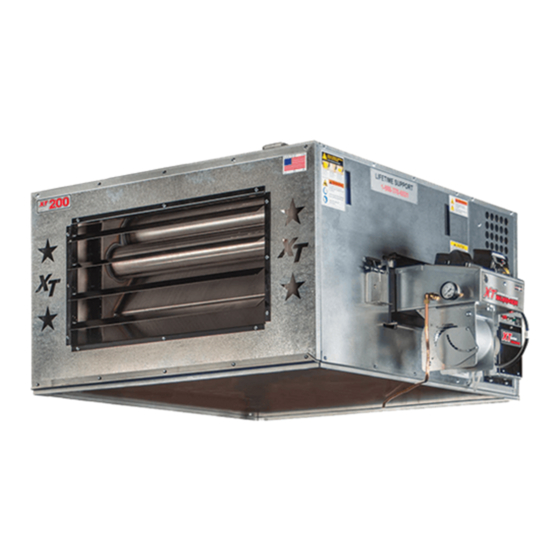
Used 5W to 50W Crankcase Oils (including synthetics), used ATF, and No.2 Fuel Oils • The Lanair Heater provides the owner with a dependable, versatile, and simple means of burning No. 2 fuel oil, used crankcase oils (5W through 50W), and used ATF. Maintained correctly, the heater will give you years of service. - Page 8 Section 1 - General Specifications & Safety XT-150 FRONT XT-250 FRONT QUESTIONS?... Contact Customer Service at 1-888-370-6531 M-F 8:00 am- 4:15 pm CST...
- Page 9 Section 1 - General Specifications & Safety XT-200 FRONT XT-300 FRONT Visit our website at: www.lanair.com...
- Page 10 Section 1 - General Specifications & Safety XT-150/200 18” Top View 4.5” 7” 22.5” 40.5” 28.75” 54” 11.5” 48” Right Side 26” 24.25” Left Side 5” 6” diameter exhaust QUESTIONS?... Contact Customer Service at 1-888-370-6531 M-F 8:00 am- 4:15 pm CST...
- Page 11 Section 1 - General Specifications & Safety 17.25” XT-250/300 5.75” Top View 24” 5.25” 45.75” 25” 58.5” 11.5” 47” Right Side 38” 36” 7.75” 8” diameter Left Side exhaust Visit our website at: www.lanair.com...
- Page 12 Section 1 - General Specifications & Safety Description Adjustable Air Flow Louvers Mounting Holes Fan Limit Switch Top Exhaust Port (Alternate) Flame View Port Burner Assembly Electrical Connections Cover Secondary Air Filter/Regulator Location Fan Assembly Side Exhaust Port (Primary) Rear Ash Box Cover QUESTIONS?...
-
Page 13: Systems & Controls
The Air Filter/Regulator performs two functions: It removes condensation and dirt from the air while controlling the amount of air pressure reaching the nozzle and air operated fuel valve. The Air/Filter Regulator is mounted on the cabinet near the burner. Visit our website at: www.lanair.com... - Page 14 Section 2 - Systems & Controls Electric Air-Solenoid Valve The electric air-solenoid valve is controlled by the oil primary control. It acts as a shut-off valve, (it’s open during operation, and closed when the burner is off ). The electric air -solenoid valve is located inside the burner’s electrical box.
- Page 15 Section 2 - Systems & Controls XT Series Burner NOTE: This burner is intended for use with Lanair waste oil fired heaters only Description Burner Assembly- Mounting Plate w/ Gasket Performance Ratings Ignition Transformer Voltage ........... 115 vac Fuel Line Inlet Fuel Pressure Gauge Cycles ............
- Page 16 Section 2 - Systems & Controls Pump Assembly for use with Bypass Regulator Pump Assembly- Description Pump Platform Performance Ratings Pump Motor Voltage ..... . .115 vac Pump Guard Cycles .
- Page 17 Pump Motor ....0.59 amps Easy Flow Bleed Valve Max. Pumping Distance ..100 feet 1/4” NPT Inlet 1/8” NPT Outlet Pump-Motor Coupling Line to Burner Pressure-Relief Valve Return to Tank Visit our website at: www.lanair.com...
-
Page 18: Heater Installation
4. Install the heater in a location to permit the fuel supply to be as close as possible. 5. If the heater is not installed on a tank stand supplied by Lanair, a metering pump may be desired in order to eliminate the need to adjust oil flow from a distance. - Page 19 Compressed-air supply, electrical shutoff switch, tank vent, 7. Secondary Air Regulator and additional chimney material not included. Installation 8. Oil-Bypass Pressure Regulator configurations vary. Additional materials will be necessary. 9. Tank-Mount Support Legs Contact Lanair for Assistance with special circumstances. Visit our website at: www.lanair.com...
- Page 20 Installation 8. Oil-Bypass Pressure Regulator configurations vary. Additional materials will be necessary. 9. Ceiling-Mount Support Rods Contact Lanair for Assistance with special circumstances. (not included) QUESTIONS?... Contact Customer Service at 1-888-370-6531 M-F 8:00 am- 4:15 pm CST...
-
Page 21: Chimney /Vent System
7. Slip Connector (14”) when installing. If your installation fails to acheive proper 8. Black ( Single Wall) Pipe (24”) draft, consider lengthening the vertical chimney. 9. Black (Single Wall) Tee Contact Lanair for Assistance with special circumstances. Visit our website at: www.lanair.com... - Page 22 If your installation fails to acheive proper draft, consider lengthening the vertical chimney. Contact Lanair for Assistance with special installation circumstances. 6. To prevent the drawing of exhaust gases into the build- ing, keep the barometric draft control at least 3 feet from any fan, blower, etc..
- Page 23 NOTE: Do not install chimney in front of the heater (in air stream of fan) Chimney Draft Requirements The Lanair heater should have a (negative) -0.02 draft reading when cold, and a (negative) -0.05 when hot. Check the heater after it has been running for 45 minutes. If the reading is not what it should be, adjust the barometric damper to acheive proper draft.
- Page 24 Please consult with Lanair for guidance in these cases. It is always preferable to install the chimney flue through the roof in order to ensure proper draft and minimize horizontal connectors that can collect debris and mois- ture.
- Page 25 (raising the manometer reading). NOTE: Keep the damper free of dust and debris and check for proper draft daily Visit our website at: www.lanair.com...
- Page 26 Section 5 - Fuel Supply Tank Installation General Requirements • The fuel supply tank and supply lines must be installed in accordance with the National Fire Protection Association requirements, as well as State and Local ordinances. • Check state and local codes. In many areas, regulations require oil storage tanks located inside not to exceed 275 gallons individually, and not to exceed a total capacity of 550 gallons in one building.
- Page 27 Concrete Anchor Tank-Mounted Installation uggestion only. Anchoring (not included) ary per individual applications Many installations take advantage of Lanair’s prefabricated tank-mounting hardware to nts. Check state and local codes simplify the installation and operation of the heater. • After anchoring the...
- Page 28 Section 5 - Fuel Supply Tank Installation Bypass-Regulator Pump Installation The oil-pressure bypass regulator pump maintains consistent fuel pressure to the TOP VIEW burner and returns excess fuel / fuel pres- sure to the tank. The regulator controls Tank Gauge Port the amount of oil being supplied to the Fuel Pickup burner and allows for adjustments.
- Page 29 P/N 9807 Metering Pump Assembly 1/2” Pickup Tube Check Valve P/N 8662 Suction Line Strainer P/N 8748 Drain Valve SIDE VIEW FRONT VIEW Bottom of strainer must be 6” from the bottom of the tank Visit our website at: www.lanair.com...
-
Page 30: Installation
5. The fuel pump contains an internal strainer that periodically needs to be cleaned. This internal strainer is mounted behind the pump cover. Before removing the pump cover make sure you have a new gasket on hand. Contact the Lanair Customer Service Department for the proper gasket for your model of pump, at 1-888-370-6531. - Page 31 P. Port from the outlet side of your fuel supply Reducer pump. Install 1/2” O.D. min. copper tubing. Failure to install this line properly will result Fuel Return to in damage to your heater, and will void your Top of Tank warranty. Visit our website at: www.lanair.com...
- Page 32 Section 7 - Air Supply Installation General Requirements 1. The air supply source must be capable of producing 2.0 CFM @ 30 PSI. 2. Install a shut off valve in the air supply line for service. Install a primary air filter/regulator with a gauge (capable of reading line pres- sure) in the air supply line prior to the air filter/regulator mounted on the furnace.
-
Page 33: Electrical Connections/Wiring Diagram
Keep the power off until the heater is ready to be started. Remove wires from the block by inserting a small flat tip screwdriver into the top slot. Push tip all the way down and push forward. Remove wire. Visit our website at: www.lanair.com... - Page 34 Section 8 - Electrical Connections Electrical Junction Box Diagram QUESTIONS?... Contact Customer Service at 1-888-370-6531 M-F 8:00 am- 4:15 pm CST...
- Page 35 Section 8 - Electrical Connections Burner Wiring Diagram 8 9 10 11 Visit our website at: www.lanair.com...
- Page 36 Section 8 - Electrical Connections WARNING: HAZARD OF ELECTRICAL SHOCK! Fuel Supply Pump Electrical Installation 1. All wiring must comply with the National Electrical Code, State and Local Ordinances, and be wired by a qualified electrician. 2. The electrical conductors to the fuel pump motor MUST be stranded 14 GA minimum. 3.
-
Page 37: Priming Fuel Pump
5” HG of vacuum. 11. Toggle the priming switch to the “RUN” position. 12. Reconnect the fuel supply line to the burner. The burner should now be ready for normal operation. Visit our website at: www.lanair.com... -
Page 38: Burner Start-Up Procedure
Section 10 - Burner Startup Procedure Waste Oil Burner Start-Up 1. Make sure the main electrical service for the heater is turned off, and locked out. 2. Check for proper draft in the chimney. Confirm that there is no positive-draft pressure (air coming DOWN the chimney, usually caused by roof-vent exhaust fans). - Page 39 90º F, or below. Fuel Bypass Regulator (not used with optional metering pump) The combustion air baffle is NOT factory set! See Section 11 - Flame Adjustment Visit our website at: www.lanair.com...
-
Page 40: Flame Adjustment
Section 11 - Flame Adjustment Flame Adjustment 1. Start the heater, let it run for at least 15 minutes to reach operating temperature before proceeding. 2. Check the chimney draft, set the barometric damper to -0.05 WC when hot and running. - Page 41 Oil too cold: check to see if preheater block is hot DO NOT OVER FIRE YOUR HEATER. IMMEDIATELY ADJUST THE BURNER TO THE PROPER FLAME LENGTH TO PREVENT DAMAGE TO YOUR HEATER. CHECK FLAME DAILY (see page 37). ADJUST ACCORDINGLY Visit our website at: www.lanair.com...
- Page 42 Ash inside the chamber is white to off white in color Flame is CORRECT If you need assistance with flame adjustment, please call Lanair’s Parts and Service Department. QUESTIONS?... Contact Customer Service at 1-888-370-6531 M-F 8:00 am- 4:15 pm CST...
-
Page 43: Maintenance Schedule / Service Adjustments
/ adjust if 12 hours (overnight) necessary. flip the pre-heater rocker switch off (light off). Remove ash from combustion chamber and heat-exchange tubes every 750-1000 hours of run time and at the end of every heating season. Visit our website at: www.lanair.com... - Page 44 Section 12 - Service / Maintenance Cleaning Primary Strainer SERVICE OF THE CANISTER OIL FILTER The primary strainer should be inspected / cleaned every 30 days of operation. The element is a washable metal element. If your waste oil is extremely dirty, this strainer may need to be cleaned more frequently.
- Page 45 Thoroughly clean and dry remaining parts Re-assemble using new small plug, spring, large plug, washer, and diaphragm (Kit P/N 9874). NOTE: Pay close attention to the posi- tions of the large and small plugs. Visit our website at: www.lanair.com...
- Page 46 Section 12 - Service / Maintenance Oil Preheater Nozzle-line Assembly Replacement-assembly Part # 81010396 Reset Switch Ignitor Assembly (Part#: 3728) Diaphragm Assembly (Part#: 9858) Snap-Disc Assembly Nozzle Assembly Air-Cartridge Heater (Part#: 9533) (Part#: 9899) [under diaphragm assembly] (Part#: 8992) Oil-Cartridge Heater (Part#: 8992) Snap-Disc Assembly Reset Switch...
- Page 47 Turbulator should measure 1/8” at the closest point. 6. Use the tool included with the heat- er to set the position of the turbula- tor, then secure it in place. Preheater-Assembly Adjustment Screw Visit our website at: www.lanair.com...
- Page 48 Section 12 - Service / Maintenance Preheater Diaphragm Breakdown Remove the four hex cap screws from the diaphragm assembly Disassemble and inspect diaphragm, spring and o-ring. Thoroughly clean remaining parts. Re-assemble the diaphragm, o-ring, spring and hex cap screws. Preheater Nozzle Cleaning / Diaphragm Assembly Replacement 1.
- Page 49 Inspect the combustion chamber and target brick. Use care when cleaning the combustion chamber area so the target brick is not disturbed. Insufficient or irregular cleaning intervals will cause inef- Step 7 ficiency, random shutdowns, and extreme damage to the combustion chamber. Visit our website at: www.lanair.com...
- Page 50 10. Before closing the combustion chamber cleanout door, replace the white gasket seal on the door (contact the Lanair Service Department). When replacing the gaskets apply a lightfilm of gasket adhesive to adhere the new gasket to the door frame. Lube the threads of the screws with a high temperature lubricant (anti-seize).
- Page 51 ....2.1 gal/hr (132 mL/min) If flow rate using a metering pump is off by more than +/- 10% contact Lanair Service at 888-370-6531.
- Page 52 Section 13 - Troubleshooting QUESTIONS?... Contact Customer Service at 1-888-370-6531 M-F 8:00 am- 4:15 pm CST...
- Page 53 • Dirt between the diaphragm and the seat in the bypass regulator when using a bypass regulator. • Dirt between the plunger and the nozzle seat. • Leak in the plumbing connections. • Leak in the pre-heater assembly (damaged or missing o ring). • Fuel pre-heater switch is off. Visit our website at: www.lanair.com...
- Page 54 Section 13 - Troubleshooting Symptom Possible Cause Corrective Action A. Burner will not start 1. Main electrical-power circuit 1. Reset breaker breaker tripped 2. Service disconnect switch off 2. Turn switch on or replace fuse or fuse blown 3. Thermostat turned down/im- 3.
- Page 55 1. Test cartridge heater(s) using not working disconnected an Ohm meter: Air heater = 112 Ω ±10% Oil heater = 37 Ω ±10% 2. Snap disc defective 2. Test snap disc for continuty when preheater is cold Visit our website at: www.lanair.com...
- Page 56 Lanair Products LLC (Manufacturer) warrants to the original purchaser of this used oil heater, that it will repair or replace at Lanair Products LLC’s option, any part which is in normal use proves to be defective in material or workmanship within a period of one year from the date of purchase, provided same is returned (transportation pre-paid) F.O.B.
- Page 57 Alteration or misuse of any part • Use of parts other than those supplied by Lanair. NOTE: Lanair may require photographs of the heater installation for warranty determination NOTE: Re-stocking fee of 20% applies on all returned parts Items Not Covered Under Warranty •...
- Page 60 Lanair Products LLC 4109 Capital Circle Janesville, Wisconsin 53546 1-888-370-6531 www.lanair.com Part # 81010423 © 2021 Lanair Products LLC Rev. A - July 20, 2021 Lanair is a registered trademark of Lanair Products LLC...
Need help?
Do you have a question about the XT Series and is the answer not in the manual?
Questions and answers