Table of Contents
Advertisement
HCD-GX90D/RV800D
SERVICE MANUAL
Ver 1.3 2003. 05
• HCD-GX90D/RV800D are the tuner, deck, DVD
and amplifier section in MHC-GX90D/RV800D.
This system incorporates Dolby* Digital, Pro Logic
Surround, DTS**, and the DTS Digital Surround
System.
* Manufactured under license from Dolby
Laboratories.
"Dolby", "Pro Logic", and the double-D symbol
are trademarks of Dolby Laboratories.
** Manufactured under license from Digital Theater
Systems, Inc. "DTS" and "DTS Digital Surround"
are registered trademarks of Digital Theater
Systems, Inc.
Amplifier section
North American model:
HCD-GX90D
Continuous RMS power output (reference)
Front speaker:
60 + 60 watts
(6 ohms at 1 kHz, 10%
THD)
Center speaker:
45 watts (8 ohms at 1 kHz,
10% THD)
Rear speaker:
40 + 40 watts
(6 ohms at 1 kHz, 10%
THD)
Sub woofer:
55 watts (4 ohms at 1 kHz,
10% THD)
Total harmonic distortion less than 0.07%
(6 ohms at 1 kHz, 70 W)
European model:
HCD-RV800D
DIN power output
Front speaker:
45 + 45 watts
(6 ohms at 1 kHz, DIN)
Center speaker:
33 watts
(8 ohms at 1 kHz, DIN)
Rear speaker:
30 watts
(6 ohms at 1 kHz, DIN)
Sub woofer:
38 watts
(4 ohms at 1 kHz, DIN)
Continuous RMS power output (reference)
Front speaker:
60 + 60 watts
(6 ohms at 1 kHz, 10%
THD)
Center speaker:
45 watts (8 ohms at 1 kHz,
10% THD)
Rear speaker:
40 + 40 watts
(6 ohms at 1 kHz, 10%
THD)
Sony Corporation
9-874-118-04
2003E16-1
Home Audio Company
© 2003.05
Published by Sony Engineering Corporation
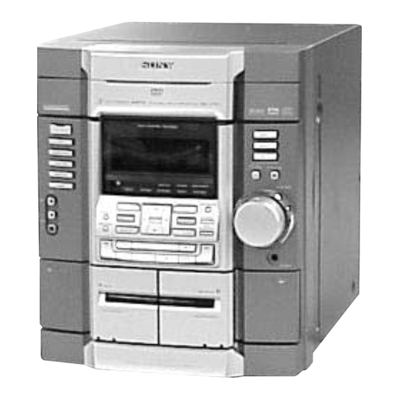
Photo : HCD-RV800D
Model Name Using Similar Mechanism
DVD
DVD Mechanism Type
Section
Base Unit Name
Model Name Using Similar Mechanism
Tape deck
Section
Tape Transport Mechanism Type
SPECIFICATIONS
Sub woofer:
55 watts
(4 ohms at 1 kHz, 10%
THD)
Music power output (reference)
Front speaker:
120 + 120 watts
(6 ohms at 1 kHz, 10%
THD)
Center speaker:
90 watts (8 ohms at 1 kHz,
10% THD)
Rear speaker:
80 + 80 watts
(6 ohms at 1 kHz, 10%
THD)
Sub woofer:
110 watts
(4 ohms at 1 kHz, 10%
THD)
COMPONENT VIDEO OUT:
Y: 1 Vp-p, 75 ohms
P
, P
: 0.7 Vp-p, 75 ohms
B
R
PHONES (stereo mini jack):
accepts headphones of
8 ohms or more
Front speaker:
accepts impedance of 6 to
16 ohms
Rear speaker
accepts impedance of
24 ohms
Center speaker
accepts impedance of
24 ohms
MINI HI-FI COMPONENT SYSTEM
US Model
Canadian Model
HCD-GX90D
AEP Model
UK Model
HCD-RV800D
NEW
CDM58D-DVBU17
DVBU17
NEW
CWM43RR-01
Sub woofer speaker
accepts impedance of
12 to 16 ohms
Disc player section
System
Compact disc and digital
audio and video system
Laser
Semiconductor laser
(DVD: λ=650 nm,
CD: λ=780 nm)
Emission duration:
continuous
Wavelength
780 – 790 nm
Frequency response
DVD (PCM 48 kHz):
2 Hz – 22 kHz (±1 dB)
CD: 2 Hz – 20 kHz
(±1 dB)
Video color system format
NTSC, PAL
CD OPTICAL DIGITAL OUT
(Square optical connector jack, rear panel)
Wavelength
660 nm
Output Level
–18 dBm
— Continued on next page —
Advertisement
Table of Contents

Related Manuals for Sony HCD-GX90D


Summary of Contents for Sony HCD-GX90D
- Page 1 Ver 1.3 2003. 05 HCD-GX90D AEP Model UK Model HCD-RV800D • HCD-GX90D/RV800D are the tuner, deck, DVD Photo : HCD-RV800D and amplifier section in MHC-GX90D/RV800D. This system incorporates Dolby* Digital, Pro Logic Model Name Using Similar Mechanism Surround, DTS**, and the DTS Digital Surround...
-
Page 2: Model Identification
(XX is a number) system has performed the self- North American model: diagnosis function. HCD-GX90D 270 watts , Contact your nearest Sony European model: dealer or local authorized Sony HCD-RV800D 270 watts service facility and give the 0.25 watts (in Power Saving Mode) 5-character service number. -
Page 3: Table Of Contents
6-32. Printed Wiring Board CRITIQUES POUR LA SÉCURITÉ DE FONCTIONNEMENT. NE – SUB TRANSFORMER Board – ····························· 54 REMPLACER CES COMPOSANTS QUE PAR DES PIÈSES SONY 6-33. Schematic Diagram DONT LES NUMÉROS SONT DONNÉS DANS CE MANUEL OU – SUB TRANSFORMER Board – ····························· 55 DANS LES SUPPÉMENTS PUBLIÉS PAR SONY. -
Page 4: General
HCD-GX90D/RV800D Ver 1.1 2002.10 Note for Service: [DISC TRAY LOCK] Releasing Procedure : The disc tray lock function for the antitheft of a demonstration disc 1. Press two buttons of x and Z simultaneously for five seconds. in the store is equipped. -
Page 5: Remote Control
HCD-GX90D/RV800D Remote control Inserting two R6 (size AA) batteries into the remote N – Z ALPHABETICAL ORDER NEXT eh (18, 27) A – M Number buttons qs (19, 27, 39, ALBUM +/– wd wl (19, 20, 26) 40, 42, 49) -
Page 6: Disassembly
HCD-GX90D/RV800D SECTION 2 DISASSEMBLY • The equipment can be removed using the following procedure. CASE (TOP) DVD LID FRONT PANEL SECTION TAPE MECHANISM DECK DVD MECHANISM DECK BLOCK (CWM43RR-01) SUB TRANSFORMER BOARD, PANEL BOARD, SUB PANEL BOARD, VIDEO BOARD, MB BOARD... -
Page 7: Case (Top)
HCD-GX90D/RV800D Note: Follow the disassembly procedure in the numerical order given. 2-1. Case (Top) 4 case 3 seven screws (BVTT 3 × 6) 2 three screws (case 3 TP2) 1 three screws (case 3 TP2) 2-2. Lid (DVD) DVD mechanism deck (CDM58D-DVBU17) 1 T urn the pulley to the direction of arrow. -
Page 8: Front Panel Section
HCD-GX90D/RV800D 2-3. Front Panel Section front panel section screw (BVTP 3 × 8) connector (CN502) screw (BVTP 3 × 8) chassis section connector (CN603) connector (CN602) flat type wire (CN605) three screws (BVTP 3 × 8) 2-4. DVD Mechanism Deck (CDM58D-DVBU17) -
Page 9: Tape Mechanical Deck (Cwm43Rr-01)
HCD-GX90D/RV800D 2-5. Tape Mechanical Deck (CWM43RR-01) panel section screws (BVTP 2.6 × 8) 1 six tape mechanism deck (CWM43RR-01) -
Page 10: Panel Board, Sub Panel Board
HCD-GX90D/RV800D 2-6. PANEL Board, SUB PANEL Board, REMOTE Board 1 volume knob front panel two claws two claws 9 REMOTE board qs four screws (BVTP 2.6 × 8) connector (CN1006) 3 five screws (BVTP 2.6 × 8) qf SUB PANEL board... -
Page 11: Cassette Holder
HCD-GX90D/RV800D 2-7. Cassette Holder 3 cassette door, spring (B) 4 cassette, holder (L) 8 cassette, holder (R) 7 cassette door, spring (A) panel section 2-8. SUB TRANSFORMER Board, Back Panel, DC Fan (M961) back panel 0 three screws (BVTP 3 × 8) -
Page 12: Transformer Board, Main Board
HCD-GX90D/RV800D 2-9. TRANSFORMER Board, MAIN Board 0 two screws 9 two screws (BVTP 3 × 8) cover (heat sink) (BVTT 3 × 6) 8 three screws 5 two screws (BVTT 3 × 6) (BV 4 × 8) TRANSFORMER board SURROUND board and... -
Page 13: Video Board, Mb Board
HCD-GX90D/RV800D Ver 1.2 2002.11 2 flat type wire 2-11. VIDEO Board, MB Board (CN503,CN302) 3 two screws (BVTP 3 × 8) 7 two screws 1 flat type wire (CN501,CN202) (BVTP 3 × 8) 8 bracket (AL) 0 two screws (BVTP 3 × 8) -
Page 14: Optical Pick-Up
HCD-GX90D/RV800D 2-13. Optical Pick-up 3 step screw (L) 4 step screw (L) insulator insulator 9 optical pick-up 5 step screw (L) insulator 1 floating screw (PTPWH M2.6) 0 holder (DBU1) assy 2-14. MOTOR Board, DIODE Board, SENSOR Board screw (PTPWH 2.6 × 8) -
Page 15: Test Mode
HCD-GX90D/RV800D Ver 1.1 2002.10 SECTION 3 TEST MODE [Cold Reset] [GC Test Mode] • The cold reset clears all data including preset data stored in the • This mode is used to check the FL tube, LED, keyboard, vol- RAM to initial conditions. Execute this mode when returning ume and phones. - Page 16 HCD-GX90D/RV800D [MC Test Mode] [Aging Mode] • This mode is used to check operations of the respective sections This mode can for operation check of tape deck section. of Amplifier, Tuner, and Tape. • If an error occurred: Procedure: The aging operation stops and display then status.
- Page 17 HCD-GX90D/RV800D Ver 1.3 2003.05 [DVD Service Mode] [DVD and CD Ship Mode (No Memory Clear)] • The sequence during the aging mode is following as below. • This mode moves the position to the position durable to vibra- tion Use this mode when returning the set to the customer after Aging mode sequence (DVD section): repair.
-
Page 18: Mechanical Adjustments
HCD-GX90D/RV800D SECTION 4 MECHANICAL ADJUSTMENTS [REPEAT 5 LIMIT OFF MODE] Precaution • This mode is used to enable infinite repetitions. 1. Clean the following parts with a denatured alcohol-moistened Normally, the number of repetitions allowed is 5. swab: Procedure: record/playback heads pinch rollers 1. -
Page 19: Electrical Adjustments
HCD-GX90D/RV800D SECTION 5 ELECTRICAL ADJUSTMENTS 2. Turn the adjustment screw and check output peaks. If the peaks DECK SECTION 0 dB=0.775 V do not match for L-CH and R-CH, turn the adjustment screw so that outputs match within 1dB of peak. - Page 20 HCD-GX90D/RV800D TUNER SECTION FM Tuned Level Adjustment FM RF SSG 75 Ω coaxial Carrier frequency : 98 MHz Modulation : AUDIO 1 kHz, 75 kHz FM ANTENNA terminal deviation (100%) (TM1) : 25 dB (at 75 Ω open) Output level Procedure: Supply a 25 dB 98 MHz signal from the ANTENNA terminal.
-
Page 21: Diagrams
HCD-GX90D/RV800D SECTION 6 DIAGRAMS 6-1. Block Diagrams – DVD DSP Section – DOUT OPTICAL PICK-UP IC509 BLOCK IC001 LRCK CD DECODER (KHM-240AAA) DVD/CD RF AMP SERVO DSP PCMD IC206 DVDRFP RFAC 50 RFAC DOUT IC701 DVD SYSTEM PROCESSOR DVD DECODER... -
Page 22: Dvd Sys Section
HCD-GX90D/RV800D – DVD SYS Section – IC1001 IC1104(3/3) DISPLAY CONTROL MASTER CONTROL Q1004-1008 D1001-1005 S1002-1014 S1062 Q1010-1012 D1007-1009 FUNCTION DISPLAY 22 KEY0 ENTER 73 DISPLAY KEY GAME-MIXING S1061 Q1009 S1022-1034 GAME-LED POWER POWER KEY POWER DRIVER FUNCTION MD/VIDEO KEY1 DRIVER... -
Page 23: Tuner Section
HCD-GX90D/RV800D – Tuner Section – AM/FM IF MPX ( EXCEPT AEP,UK) (AEP, UK) FE3(AEP,UK) IC11 RF IF L-CH MAIN ANT IN IF OUT FM IF L OUT SECTION FM 75Ω OSC OUT (Page 24) FM TUNED R OUT R-CH LEVEL... -
Page 24: Main Section
HCD-GX90D/RV800D – Main Section – Q110 MREQ • RCH is omitted due to same as LCH • Signal Path IC302 IC506 D/A CONVERTER IC105 : FM BUFFER SWITCH : DVD 34 MDI VOUT1 35 MC VOUT2 : DIGITAL OUT 36 ML... -
Page 25: Circuit Boards Location
HCD-GX90D/RV800D 6-2. Circuit Boards Location THIS NOTE IS COMMON FOR PRINTED WIRING BOARDS AND SCHEMATIC DIAGRAMS. (In addition to this, the necessary note is printed in each block.) Note on Schematic Diagram: Note on Printed Wiring Boards: • All capacitors are in µF unless otherwise noted. pF: µµF •... -
Page 26: Printed Wiring Board - Rf Board
HCD-GX90D/RV800D 6-3. Printed Wiring Board – RF Board – • See page 25 for Circuit Boards Location. IC001 (Page 28) • Semiconductor Location Ref. No. Location D001 D002 IC001 Q001 Q002... -
Page 27: Schematic Diagram - Rf Board
HCD-GX90D/RV800D 6-4. Schematic Diagram – RF Board – • See page 55 for Wavefoms. • See page 64 for IC Block Diagrams. CN002 C027 C031 R026 R023 1000p JL005 C030 C025 R025 C029 JL004 CN001 C013 R024 JL007 C006 C008... -
Page 28: Printed Wiring Board - Mb Board (Side A)
HCD-GX90D/RV800D 6-5. Printed Wiring Board – MB Board (Side A) – • See page 25 for Circuit Boards Location. (Page 26) CN501 EXCEPT IC701 IC509 • Semiconductor Location Ref. No. Location D301 D302 IC901 IC215 IC206 IC215 IC302 IC303 IC509... -
Page 29: Printed Wiring Board - Mb Board (Side B)
HCD-GX90D/RV800D 6-6. Printed Wiring Board – MB Board (Side B) – • See page 25 for Circuit Boards Location. IC706 IC703 IC501 IC503 • Semiconductor Location Ref. No. Location IC903 IC907 D901 IC202 IC205 IC203 IC205 IC210 IC305 IC501 IC503... -
Page 30: Schematic Diagram - Mb Board (1/6)
HCD-GX90D/RV800D 6-7. Schematic Diagram – MB Board (1/6) – • See page 58 for IC Pin Function Description. IC703(2/2) NJM3404AM-TE2 TP701 R544 100k C523 R550 R545 100k R540 1500p IC706 MSM51V18165F -60TSKR1 TP703 C715 FL706 R700 R541 0.0015 POWER-EMIS 8.2k... -
Page 31: Schematic Diagram - Mb Board (2/6)
HCD-GX90D/RV800D 6-8. Schematic Diagram – MB Board (2/6) – • See page 61 for IC Pin Function Description. • See page 55 for Wavefoms. R729 FL901 POWER-EMIS R805 C901 100 4V C906 0.01 C902 0.01 R901 IC903 BR24C08F-E2 C918 0.01... -
Page 32: Schematic Diagram - Mb Board (3/6)
HCD-GX90D/RV800D 6-9. Schematic Diagram – MB Board (3/6) – CN202 JL209 JL208 JL207 R267 JL206 JL212 R268 R270 R271 JL205 C202 C216 C201 C205 C218 JL204 R277 R278 R279 R280 R281 JL203 R262 R263 R264 R265 R266 C225 JL202 C228 R250 0.01... -
Page 33: Schematic Diagram - Mb Board (4/6)
HCD-GX90D/RV800D 6-10. Schematic Diagram – MB Board (4/6) – IC202 MT48LC4M32B2-7 C217 0.01 C219 0.01 C226 0.01 C234 0.01 C238 0.01 C239 0.01 R251 C242 0.01 C244 0.01 C245 0.01 C248 0.01 C249 0.01 C253 0.01 C254 C257 C204 C258 FL202 0.01... -
Page 34: Schematic Diagram - Mb Board (5/6)
HCD-GX90D/RV800D 6-11. Schematic Diagram – MB Board (5/6) – • See page 63 for IC Block Diagrams. R326 FL302 R315 R313 C302 0.01 C303 JW307 C308 R307 D301 0.01 1SS355TE JW309 C324 C307 6.3V C325 FL303 C327 IC302 C326 PCM1608... -
Page 35: Schematic Diagram - Mb Board (6/6)
HCD-GX90D/RV800D 6-12. Schematic Diagram – MB Board (6/6) – • See page 63 for IC Block Diagrams. CL505 MNT0 CL504 MNT1 R587 CL503 MNT2 CL502 MNT3 CL501 FL502 C567 PWR-EMIS C568 R569 10 10V C522 R536 R670 R537 R671 CN501... -
Page 36: Printed Wiring Board - Tc Board
HCD-GX90D/RV800D 6-13. Printed Wiring Board – TC Board – • See page 25 for Circuit Boards Location. • Semiconductor Location Ref. No. Location IC303 IC601 IC601 Q601 Q602 Q603 Q604 Q605 Q606 Q607 Q608 Q609 Q610 Q611 (Page 38) (Page 38) -
Page 37: Schematic Diagram - Tc Board
HCD-GX90D/RV800D 6-14. Schematic Diagram – TC Board – C657 C624 R627 C621 C620 R622 C662 0.01 C617 R621 C626 47 16V CN602 R620 C615 C627 1 50V R618 IC601 HA12237F R617 CN603 4.7k R616 4.7k R615 4.7k CN608 C630 Q606... -
Page 38: Printed Wiring Board - Main Section
HCD-GX90D/RV800D 6-15. Printed Wiring Board – Main Section – • See page 25 for Circuit Boards Location. (Page 42) (Page 28) (Page 42) (Page 51) (Page 28) IC51 IC1104 IC703 IC11 (Page 48) RV800D IC105 IC81 IC706 IC705 IC102 IC704... -
Page 39: Schematic Diagram - Main Section (1/3)
HCD-GX90D/RV800D 6-16. Schematic Diagram – Main Section (1/3) – • See page 66 for IC Block Diagrams. • See page 55 for Wavefoms. JR11 JR10 BN1A4M JR13 JR12 0.01 0.01 0.01 JR14 2SC1674 4700p JR15 JR19 47000p 220k 3.3k RB41... -
Page 40: Schematic Diagram - Main Section (2/3)
HCD-GX90D/RV800D 6-17. Schematic Diagram – Main Section (2/3) – Q102 C172 C106 2SC3623ATP R109 R193 3.9k C104 100p R106 R147 J101 100k R107 Q152 4.7k 2SC3623ATP C155 R156 100p C157 100k R157 C161 C162 0.0047 R176 4.7k R151 R154 R180 150k 2.2k... -
Page 41: Schematic Diagram - Main Section (3/3)
HCD-GX90D/RV800D 6-18. Schematic Diagram – Main Section (3/3) – • See page 56 for IC Pin Function Description. • See page 55 for Wavefoms. Q720 Q721 Q719 BN1F4M BN1F4M BN1F4M D735 R755 1SS355TE CN708 C739 R125 C791 R753 100k R763... -
Page 42: Printed Wiring Board - Video Board
HCD-GX90D/RV800D 6-19. Printed Wiring Board – VIDEO Board – • See page 25 for Circuit Boards Location. IC509 • Semiconductor Location IC506 IC510 Ref. No. Location D502 D503 D504 D505 D506 IC505 D507 D508 D509 D510 D511 D512 D513 D514... -
Page 43: Schematic Diagram - Video Board
HCD-GX90D/RV800D 6-20. Schematic Diagram – VIDEO Board – • See page 65 for IC Block Diagrams. C506 R186 2.2k IC505(1/2) NJM2100M C553 0.0047 R188 2.2k Q109 R509 C505 2SC3623 100k JW515 R187 R532 R531 R530 2.2k C552 1.5k 1.5k R508 CN508 0.0012... -
Page 44: Printed Wiring Board - Front Amp Board
HCD-GX90D/RV800D 6-21. Printed Wiring Board – FRONT AMP Board – • See page 25 for Circuit Boards Location. IC922 IC932 IC921 IC923 IC934 IC201 (Page 52) (Page 38) (Page 46) (Page 38) • Semiconductor Location Ref. No. Location Ref. No. Location Ref. No. Location... -
Page 45: Schematic Diagram - Front Amp Board
HCD-GX90D/RV800D 6-22. Schematic Diagram – FRONT AMP Board – IC201 STK402-070S IC932 CN271 D271 D5SBA204101 C271 100V C273 2200 IC934 TA7805S CN202 C272 EH-L 100V IC923 TA7812S C274 JW933 2200 R205 0.22 TM201 R211 1/4W RY281 L281 IC922 TA7809S C206... -
Page 46: Printed Wiring Board - Surround Board
HCD-GX90D/RV800D 6-23. Printed Wiring Board – SURROUND Board – • See page 25 for Circuit Boards Location. IC302 IC300 (Page 52) (Page 42) (Page 44) • Semiconductor Location Ref. No. Location Ref. No. Location D301 IC302 D341 D351 Q301 D371... -
Page 47: Schematic Diagram - Surround Board
HCD-GX90D/RV800D 6-24. Schematic Diagram – SURROUND Board – CN302 IC300 IC302 STK402-040 STK402-040 C371 C373 D371 0.01 2200 D5SBA204101 NO371 R411 100 1/4W FR C374 2200 C372 R461 0.01 100 1/4W FR R420 C458 C408 1/4W R301 C301 ✽ R381 1.5k... -
Page 48: Printed Wiring Board - Panel Section
HCD-GX90D/RV800D 6-25. Printed Wiring Board – Panel Section – • See page 25 for Circuit Boards Location. IC1003 IC1001 20 21 IC1002 KARAOKE (Page 42) (Page 38) • Semiconductor Location Ref. No. Location Ref. No. Location Ref. No. Location D1002... -
Page 49: Schematic Diagram - Panel Section (1/2)
HCD-GX90D/RV800D 6-26. Schematic Diagram – Panel Section (1/2) – • See page 55 for Wavefoms. Q1003 Q1002 Q1001 CN1001 BA1L3Z BA1L3Z BA1L3Z FL1001 AMP-L JW1007 JW1008 JW1009 JW1010 R1080 100k R1079 R1078 100k 100k J1001 R1015 C1035 FB1003 100p C1156... -
Page 50: Schematic Diagram - Panel Section (2/2)
HCD-GX90D/RV800D 6-27. Schematic Diagram – Panel Section (2/2) – R1009 R1010 R1011 R1012 R1013 4.7k 6.8k R1022 R1023 R1024 R1025 R1026 R1027 R1028 R1029 R1030 R1031 R1032 R1033 R1034 1.5k 1.5k 2.2k 3.3k 4.7k 6.8k R1050 R1051 R1052 R1053 R1054 R1055 6.8k... -
Page 51: Schematic Diagram - Sensor Section
HCD-GX90D/RV800D 6-28. Schematic Diagram – Sensor Section – • See page 65 for IC Block Diagrams. IC B/D 6-29. Printed Wiring Board – Sensor Section – • See page 25 for Circuit Boards Location. SENSOR BOARD MOTOR BOARD DRIVER BOARD... -
Page 52: Printed Wiring Board - Transformer Board
HCD-GX90D/RV800D 6-30. Printed Wiring Board – TRANSFORMER Board – • See page 25 for Circuit Boards Location. (Page 38) (Page 54) (Page 54) (Page 44) (Page 46) -
Page 53: Schematic Diagram - Transformer Board
HCD-GX90D/RV800D 6-31. Schematic Diagram – TRANSFORMER Board – CN913 T911 F914 ✽ F916 6.3A CN915 CN911 F917 6.3A JW923 ✽ F915 F918 6.3A CN914 R918 3.3M ✽ F919 R917 C929 C930 D913 D911 RD4.7F-T7B1 11ES2-NTA2B Q971 2SA1932 C913 R911 0.68... -
Page 54: Printed Wiring Board - Sub Transformer Board
HCD-GX90D/RV800D 6-32. Printed Wiring Board – SUB TRANSFORMER Board – • See page 25 for Circuit Boards Location. (Page 52) • Semiconductor Location Ref. No. Location D901 D902 D903 D904 D905 IC901 Q901 (Page 52) -
Page 55: Schematic Diagram - Sub Transformer Board
HCD-GX90D/RV800D 6-33. Schematic Diagram – SUB TRANSFORMER Board – • Waveforms – MB Board – – VIDEO Board – – RF Board – – MAIN Board – IC906 8 XTO IC503 ed C-OUT IC001 1 DVD RFP IC1104 qa SUB, CLOCK-OUT 2.9Vp-p... -
Page 56: Ic Pin Function Descriptions
HCD-GX90D/RV800D 6-34. IC Pin Function Descriptions • IC1104 M30620MCN-A04FP (MAIN Board) Pin No. Pin Name Description Pin No. Pin Name Description S-OUT SERIAL OUT CLOSE CLOSE SW S-CLK SERIAL CLOCK UP/DOWN SW BU UP/DOWN SW POWER-LED STANDBY-LED ON(L)/OFF(H) T-SENS TABLE SENSOR... - Page 57 HCD-GX90D/RV800D Pin No. Pin Name Description VACS-IN VACS IN AVSS — NO-USE — Not used V.REF — AV Referense AVCC — AVCC S-IN SERIAL IN...
- Page 58 HCD-GX90D/RV800D • IC701 CXD1882R (MB Board) Pin No. Pin Name Description 1, 2 D5, D6 Two-way data bus with the mechanism controller — Ground terminal (digital system) Two-way data bus with the mechanism controller Address signal input from the mechanism controller —...
- Page 59 HCD-GX90D/RV800D Pin No. Pin Name Description XPDI Not used VDDS — Power supply terminal (+5V) (digital system) 59, 60 HA0, HA2 Not used — Ground terminal (digital system) 62, 63 HCS0, HCS1 Not used — Power supply terminal (+3.3V) (digital system)
- Page 60 HCD-GX90D/RV800D Pin No. Pin Name Description 128, 129 VCCA3, VCCA2 — Power supply terminal (+3.3V) (analog system) Signal output from the charge pump for phase comparator PDHVCC Middle point voltage input terminal for RF PLL Signal output from the charge pump for frequency comparator...
- Page 61 HCD-GX90D/RV800D • IC901 CXP973064-224R (MB Board) Pin No. Pin Name Description EEP SO Not used SDEN Serial data enable signal output to DVD/CD RF amplifier DOCTRL/ Digital out on/off control signal output to the digital signal processor ISBTEST “L”: digital out off, “H”: digital out on...
- Page 62 HCD-GX90D/RV800D Pin No. Pin Name Description TRAY OUT Disc tray out detection signal input terminal Not used GFS DVD Guard frame sync signal input from the DVD decoder MUTE CD Muting on/off control signal output to the digital signal processor “H”: muting on MUTE 2D Muting on/off control signal output to the motor/coil driver “H”: muting on...
-
Page 63: Ic Block Diagrams
HCD-GX90D/RV800D • IC Block Diagrams – MB Board – IC302 PCM1608Y/2K 32 31 30 36 35 34 33 VCC3 FUNCTION AGND3 CONTROL VCC4 INTERFACE AGND4 SYSTEM SCKI CLOCK SCKO MANAGER VOUT8 AGND6 VCC5 LRCK AGND5 TEST 4X/8X ENHANCED VOUT7 OVER SAMPLING... - Page 64 HCD-GX90D/RV800D – RF Board – IC001 CXD1881AR 64 63 62 61 60 59 55 54 53 52 FAST ATTACK INPUT OUTPUT HOLD FULL WAVE AGC CHARGE INHIBIT RECTIFER PUMP PROGRAMMABLE FROM S-PORT INPUT EQUALIZER DVDRFP FILTER BIAS DVDRFN DIFFERENTIATOR INPUT...
-
Page 65: Video Board
HCD-GX90D/RV800D – VIDEO Board – IC502 NJM2244M-TE2 IC509, IC510 M62429P VIN2 VOUT2 CLOCK VIN1 VR 2 75 Ω VOUT VOL AMP 2 VREF DRIVER LOGIC CONTROL VOL AMP 1 REF AMP VIN2 BIAS VR 1 VIN3 (MUTE) VIN1 VOUT1 DATA... -
Page 66: Main Board
HCD-GX90D/RV800D – MAIN Board – IC11 LA1845 PF.AMP DEOODER PILOT BUFF ANTI-BIRDIE CANCEL P-DET STEREO ø LEVEL AM/FM COMP S-CURVE BUFF PILOT π 304kHz 19k 0 TUNING DRIVE IC51 LC72121... -
Page 67: Exploded Views
HCD-GX90D/RV800D SECTION 7 EXPLODED VIEWS NOTE: • -XX, -X mean standardized parts, so they may • The mechanical parts with no reference number The components identified by mark 0 or have some differences from the original one. in the exploded views are not supplied. -
Page 68: Front Panel Section
X-4954-697-1 PANEL ASSY, FRONT (GX90D:US) 4-231-836-01 SPRING (HEART CAM-A) X-4954-698-1 PANEL ASSY, FRONT (GX90D:CND) 4-231-841-02 SPRING (HEART CAM-B) X-4954-699-1 PANEL ASSY, FRONT (RV800D) 4-963-404-22 EMBLEM (5-A), SONY 4-225-252-01 CUSHION (FOOT) 4-240-174-01 HOLDER, FL TUBE 4-238-619-01 CASS WINDOW (L) A-4729-731-A REMOTE MBOARD, COMPLETE 4-240-162-01 HOLDER (L), CASSETTE 4-951-620-01 SCREW (2.6X8), +BVTP... -
Page 69: Chassis Section
HCD-GX90D/RV800D 7-3. Chassis Section not supplied not supplied not supplied not supplied not supplied not supplied not supplied T911 not supplied F919 F918 not supplied F915 F914 not supplied not supplied F916 F917 Ref. No. Part No. Description Remarks Ref. No. -
Page 70: Dvd Mechanism Deck Section
HCD-GX90D/RV800D Ver 1.3 2003.05 7-4. DVD Mechanism Deck Section (CDM58D-DVBU17) M721 supplied Ref. No. Part No. Description Remarks Ref. No. Part No. Description Remarks 4-218-254-21 SCREW (M2.6) +PTPWH 4-221-683-01 GEAR (U) 4-231-187-01 CAM (RELAY) 4-221-678-01 CAM (CONTROL) X-4954-616-1 LEVER (CHANGE 2) ASSY... -
Page 71: Electrical Parts List
HCD-GX90D/RV800D SECTION 8 DIODE DRIVER ELECTRICAL PARTS LIST FRONT AMP NOTE: • Due to standardization, replacements in the • RESISTORS • SEMICONDUCTORS In each case, u: µ, for example: parts list may be different from the parts All resistors are in ohms. - Page 72 HCD-GX90D/RV800D FRONT AMP MAIN Ref. No. Part No. Description Remarks Ref. No. Part No. Description Remarks < DIODE > R226 1-249-426-11 CARBON 5.6K 1/4W R227 1-249-431-11 CARBON 1/4W D201 8-719-991-33 DIODE 1SS133T-77 D221 8-719-991-33 DIODE 1SS133T-77 R228 1-249-435-11 CARBON 1/4W...
- Page 73 HCD-GX90D/RV800D MAIN Ref. No. Part No. Description Remarks Ref. No. Part No. Description Remarks 1-162-974-11 CERAMIC CHIP 0.01uF 1-162-974-11 CERAMIC CHIP 0.01uF (RV800D) 1-162-974-11 CERAMIC CHIP 0.01uF 1-126-961-11 ELECT 2.2uF 20.00% 50V 1-162-974-11 CERAMIC CHIP 0.01uF (RV800D) 1-126-947-11 ELECT 47uF 20.00% 16V...
- Page 74 HCD-GX90D/RV800D MAIN Ref. No. Part No. Description Remarks Ref. No. Part No. Description Remarks C145 1-115-868-11 ELECT 0.22uF 20.00% 50V C779 1-107-701-11 ELECT 47uF 20.00% 16V C147 1-136-159-00 FILM 0.033uF 5.00% 50V C791 1-126-963-11 ELECT 4.7uF 20.00% 50V C148 1-115-870-11 ELECT 0.47uF...
- Page 75 HCD-GX90D/RV800D MAIN Ref. No. Part No. Description Remarks Ref. No. Part No. Description Remarks D611 8-719-988-61 DIODE 1SS355TE-17 IC81 8-759-541-48 IC BU1924 (RV800D) D703 8-719-988-61 DIODE 1SS355TE-17 IC101 8-759-710-97 IC NJM4565M (TE2) D704 8-719-988-61 DIODE 1SS355TE-17 IC102 6-702-422-11 IC M61519FPD61G...
- Page 76 HCD-GX90D/RV800D MAIN Ref. No. Part No. Description Remarks Ref. No. Part No. Description Remarks < COIL > 1-216-833-11 METAL CHIP 1/10W 1-216-827-11 METAL CHIP 3.3K 1/10W 1-412-957-11 INDUCTOR 33uH (RV800D) 1-412-963-11 INDUCTOR 100uH (RV800D) 1-216-814-11 METAL CHIP 1/10W L702 1-419-253-11 INDUCTOR...
- Page 77 HCD-GX90D/RV800D MAIN Ref. No. Part No. Description Remarks Ref. No. Part No. Description Remarks R101 1-216-825-11 METAL CHIP 2.2K 1/10W R180 1-216-833-11 METAL CHIP 1/10W R102 1-216-819-11 METAL CHIP 1/10W R183 1-216-837-11 METAL CHIP 1/10W R103 1-216-833-11 METAL CHIP 1/10W...
- Page 78 HCD-GX90D/RV800D MAIN Ref. No. Part No. Description Remarks Ref. No. Part No. Description Remarks R766 1-216-821-11 METAL CHIP 1/10W R851 1-216-833-11 METAL CHIP 1/10W R767 1-216-841-11 METAL CHIP 1/10W R852 1-216-809-11 METAL CHIP 1/10W R768 1-216-833-11 METAL CHIP 1/10W R853...
- Page 79 HCD-GX90D/RV800D MAIN Ref. No. Part No. Description Remarks Ref. No. Part No. Description Remarks < TRANSFORMER > C251 1-164-947-11 CERAMIC CHIP 0.01uF C252 1-164-947-11 CERAMIC CHIP 0.01uF 1-435-792-11 TRANSFORMER, DISCRIMINATOR C253 1-164-947-11 CERAMIC CHIP 0.01uF < TERMINAL > C254 1-117-370-11 CERAMIC CHIP...
- Page 80 HCD-GX90D/RV800D Ref. No. Part No. Description Remarks Ref. No. Part No. Description Remarks C517 1-117-370-11 CERAMIC CHIP 10uF C725 1-107-820-11 CERAMIC CHIP 0.1uF C518 1-164-947-11 CERAMIC CHIP 0.01uF C726 1-107-820-11 CERAMIC CHIP 0.1uF C519 1-164-943-11 CERAMIC CHIP 0.01uF 10.00% 16V...
- Page 81 HCD-GX90D/RV800D Ref. No. Part No. Description Remarks Ref. No. Part No. Description Remarks < CONNECTOR > IC904 8-759-083-94 IC TC7W74FU (TE12R) IC906 6-700-407-01 IC SM8707GV-G-E2 CN201 1-784-364-21 CONNECTOR, FFC/FPC 4P IC907 8-759-583-47 IC uPC2933T-E2 CN202 1-784-376-11 CONNECTOR, FFC/FPC 17P CN302 1-793-991-11 CONNECTOR, FFC/FPC 23P <...
- Page 82 HCD-GX90D/RV800D Ref. No. Part No. Description Remarks Ref. No. Part No. Description Remarks R256 1-218-961-11 RES-CHIP 4.7K 1/16W R512 1-218-974-11 RES-CHIP 1/16W R257 1-218-961-11 RES-CHIP 4.7K 1/16W R513 1-218-974-11 RES-CHIP 1/16W R258 1-218-961-11 RES-CHIP 4.7K 1/16W R516 1-218-961-11 RES-CHIP 4.7K...
- Page 83 HCD-GX90D/RV800D Ref. No. Part No. Description Remarks Ref. No. Part No. Description Remarks R603 1-218-959-11 RES-CHIP 3.3K 1/16W R737 1-218-965-11 RES-CHIP 1/16W R604 1-218-953-11 RES-CHIP 1/16W R741 1-208-643-11 RES-CHIP 1/16W R742 1-208-643-11 RES-CHIP 1/16W R605 1-218-990-11 SHORT CHIP R743 1-208-643-11 RES-CHIP...
- Page 84 HCD-GX90D/RV800D MOTOR PANEL Ref. No. Part No. Description Remarks Ref. No. Part No. Description Remarks R922 1-208-643-11 RES-CHIP 1/16W < SWITCH > R923 1-218-945-11 RES-CHIP 1/16W S701 1-771-822-11 SWITCH, LEVER (SLIDE)(OPEN/CLOSE) R925 1-218-941-81 RES-CHIP 1/16W ************************************************************ R926 1-218-941-81 RES-CHIP 1/16W...
- Page 85 HCD-GX90D/RV800D PANEL Ref. No. Part No. Description Remarks Ref. No. Part No. Description Remarks < CONNECTOR > R1017 1-249-417-11 CARBON 1/4W F CN1002 1-785-316-11 PIN, CONNECTOR (STRAIGHT) 4P R1018 1-249-417-11 CARBON 1/4W F CN1003 1-785-315-11 PIN, CONNECTOR (STRAIGHT) 3P R1019...
- Page 86 HCD-GX90D/RV800D PANEL REMOTE Ref. No. Part No. Description Remarks Ref. No. Part No. Description Remarks S1004 1-762-196-21 SWITCH, TACT (TAPE A/B) A-4728-690-A RF BOARD, COMPLETE S1005 1-762-196-21 SWITCH, TACT (VIDEO MD) ******************* S1006 1-762-196-21 SWITCH, TACT (GAME) < CAPACITOR >...
- Page 87 HCD-GX90D/RV800D SENSOR SUB PANEL Ref. No. Part No. Description Remarks Ref. No. Part No. Description Remarks < IC > < RESISTOR > IC001 8-752-417-53 IC CXD1881AR R711 1-249-417-11 CARBON 1/4W F R712 1-249-417-11 CARBON 1/4W F < COIL > R713...
- Page 88 HCD-GX90D/RV800D SUB PANEL SUB TRANSFORMER SURROUND Ref. No. Part No. Description Remarks Ref. No. Part No. Description Remarks S1028 1-762-196-21 SWITCH, TACT (ALBUM-) < TRANSFORMER > S1029 1-762-196-21 SWITCH, TACT (ALBUM-) S1030 1-762-196-21 SWITCH, TACT (.) 0 T901 1-437-675-11 TRANSFORMER, POWER (GX90D)
- Page 89 HCD-GX90D/RV800D SURROUND Ref. No. Part No. Description Remarks Ref. No. Part No. Description Remarks C386 1-136-165-00 FILM 0.1uF 5.00% 50V R302 1-249-437-11 CARBON 1/4W C388 1-164-159-21 CERAMIC 0.1uF R303 1-249-415-11 CARBON 1/4W F (RV800D) R304 1-249-437-11 CARBON 1/4W 0 R305...
- Page 90 HCD-GX90D/RV800D SURROUND Ref. No. Part No. Description Remarks Ref. No. Part No. Description Remarks 0 R411 1-212-881-11 FUSIBLE 1/4W C629 1-162-292-31 CERAMIC 680PF R414 1-249-417-11 CARBON 1/4W F C630 1-126-786-11 ELECT 47uF 20.00% 16V C631 1-162-292-31 CERAMIC 680PF R419 1-249-429-11 CARBON...
- Page 91 HCD-GX90D/RV800D TRANSFORMER VIDEO Ref. No. Part No. Description Remarks Ref. No. Part No. Description Remarks R617 1-249-425-11 CARBON 4.7K 1/4W F < DIODE > R618 1-249-409-11 CARBON 1/4W F D911 8-719-024-99 DIODE 11ES2-NTA2B R620 1-249-433-11 CARBON 1/4W D912 8-719-983-88 DIODE MTZJ-T-72-33C...
- Page 92 HCD-GX90D/RV800D VIDEO Ref. No. Ref. No. Part No. Part No. Description Description Remarks Remarks Ref. No. Ref. No. Part No. Part No. Description Description Remarks Remarks C511 1-126-964-11 ELECT 10uF 20.00% 50V < DIODE > C512 1-126-964-11 ELECT 10uF 20.00% 50V...
- Page 93 HCD-GX90D/RV800D VIDEO Ref. No. Part No. Description Remarks Ref. No. Part No. Description Remarks Q501 8-729-900-89 TRANSISTOR BA1L4M-TP R582 1-249-425-11 CARBON 4.7K 1/4W F R583 1-249-437-11 CARBON 1/4W Q502 8-729-422-57 TRANSISTOR BN1A4M-TP R584 1-249-425-11 CARBON 4.7K 1/4W F Q503 8-729-422-57 TRANSISTOR...
- Page 94 HCD-GX90D/RV800D MEMO...
- Page 95 HCD-GX90D/RV800D US Model Canadian Model HCD-GX90D SERVICE MANUAL AEP Model UK Model Ver 1.3 2003.05 HCD-RV800D SUPPLEMENT-1 Subject: DVD TEST MODE (SPM-03008) 9-874-118-81...
- Page 96 HCD-GX90D/RV800D DVD TEST MODE [GENERAL DESCRIPTION] 0-1. All (All items continuous check) This menu checks all diagnostic items continuously. Normally, all The Test Mode allows you to make diagnosis and adjustment easily items are checked successively one after another automatically using the remote commander and monitor TV.
- Page 97 HCD-GX90D/RV800D 0-2-3. ROM Check Sum 1-0. ALL [10/0] The revision number of ROM (IC203) that the program for Press the key on the remote commander, and the servo set the DVD system processor (IC206) is stored. data in EEPROM will be initialized. Then, 1. DVD-SL disc, 2. CD disc and 3.
- Page 98 HCD-GX90D/RV800D 12. Tracking on 38. EQ boost adjust 13. (TC display start) 39. Auto Loop Filter Offset 14. Wait 1 sec 40. Auto track gain adjust 15. Jitter display start Search Check 16. Sled ON 41. 32 track jump forward 17.
- Page 99 HCD-GX90D/RV800D 2-1. Disc Type 2-1-3. Disc Type CD It sets up so that it may judge as a disc type of specification of the disc with which the set was inserted. Disc Type : CD disc (normal speed, 12 cm)
- Page 100 HCD-GX90D/RV800D 2-3. Track/Layer Jump 2-5. EEPROM Write Adjust Track/Layer Jump EEPROM Write Adjust FWD R.Lj L0>L1 REV L.Lj L1>L0 1. Focus Offset 3.500Tj Fine FWD U.Fj L0>L1 2. Focus Gain 4.500Tj Fine REV D.Fj L1>L0 3. Trk. Offset Coarse 5.10kTj Dirc 4.
- Page 101 HCD-GX90D/RV800D 2-7. Disc Check Memory MECHA AGING On the Test Mode Menu screen, selecting executes the aging of Disc Check Memory the mechanism deck. 1. SL Disc check 2. SL Disc check ### Aging Test MENU ### 3. SL Disc check Operation Menu 1.
- Page 102 HCD-GX90D/RV800D soon. aa: Initialization is completed or not. : Complete. • Code list of Emergency History other number : Not complete. 10: Communication to RF AMP (IC001) failed. bb: Operating status of mechanism deck at an error occurred. 11: Each servo for focus, tracking, and spindle is unlocked.
- Page 103 HCD-GX90D/RV800D VERSION INFORMATION On the Test Mode Menu screen, selecting displays the ROM version and region code. The parenthesized hexadecimal number in version field is checksum value of ROM. ## Version Information ## IF con. Ver.x. xx SYScon. Ver.x. xx...
- Page 104 HCD-GX90D/RV800D REVISION HISTORY Clicking the version allows you to jump to the revised page. Also, clicking the version at the upper right on the revised page allows you to jump to the next revised page. Ver. Date Description of Revision 2002.09...
Need help?
Do you have a question about the HCD-GX90D and is the answer not in the manual?
Questions and answers