Table of Contents
Advertisement
Advertisement
Table of Contents

Subscribe to Our Youtube Channel
Related Manuals for Yanmar 4LHA-HTP


Summary of Contents for Yanmar 4LHA-HTP
-
Page 2: Proposition 65 Warning
Congratulations on your choice of YANMAR product from YANMAR DIESEL ENGINE CO., LTD. This manual describes operation, periodic inspection and maintenance servicing for the ENGINE manufactured by YANMAR DIESEL ENGINE CO., LTD. Please read this manual carefully before use, and operate... -
Page 3: Introduction
Make sure this manual is transfered to subsequent owners. This manual should be considered a permanent part of the engin and remain it. Constant efforts are made to improve the quality and performance of Yanmar products, so some details included in this Operation Manual may differ slightly from your engine. -
Page 4: Table Of Contents
INDEX page No. INTRODUCTION ............................1 INDEX ................................2~3 1. FOR SAFE OPERATION ......................4~8 1.1 Warning Symbols .............................4 1.2 Safety Precautions ..........................5~6 1.3 Location of product safety Labels......................7~8 2. EXPLANATION OF PRODUCT ....................9~22 2.1 Use, Driving System etc...........................9 2.2 Engine Specificitions ........................10~12 2.3 Names of Parts ..........................13~15 2.4 Major Servicing Parts ..........................16 2.5 Control Equipment..........................17~22... - Page 5 5. MAINTENANCE & INSPECTION ..................42~54 5.1 List of Periodic Inspections ........................43 5.2 Periodic Inspection Items .........................44~54 5.2.1 Inspection after Initial 50 Hrs. Operation ..................44 5.2.2 Inspection Every 50Hours ....................45~47 5.2.3 Inspection Every 250 Hrs. or 1 yr...................48~51 5.2.4 Inspection Every 500 Hrs. or 2 yrs....................52 5.2.5 Inspection Every 1000 Hrs.
-
Page 6: For Safe Operation
1. FOR SAFE OPERATION Following the precautions described in this manual will enable you to use this engine with complete satisfaction. Failure to observe any of the rules and precautions, however, may result in injury, burns, fires, and engine damage. Read this manual carefully and be sure you fully understand it before beginning operation. -
Page 7: Safety Precautions
1.2 Safety Precautions (Observe these instructions for your own safety.) Precautions for Operation Burns from Scalding DANGER Never remove the filler cap of the fresh water cooler while the engine is still hot. Steam and hot water will spurt out and seriously burn you. Wait until the water temperature has dropped, then wrap a cloth around the cap and loosen it slowly. -
Page 8: Prevent Burns
Alcohol WARNING Never operate the engine while you are under the influence of alcohol or when you are ill or feel unwell as this results in accidents. Safety Precautions for Inspection Battery Fluid DANGER Battery fluid is diluted sulfuric acid. It can blind you if it gets in your eyes, or burn your skin. -
Page 9: Location Of Product Safety Labels
1.3 Location of product Safety Labels Warning device labels, Parts numbers To insure safe operation, warning device labels have been attached. Their location is shown in Part Code No. the diagram below and next page. Keep the labels 128296-07300 from becoming dirty or torn and replace them if 120324-07240 they are lost or damaged. -
Page 11: Explanation Of Product
2. EXPLANATION OF PRODUCT 2.1 Use, Driving System, etc. In the case of 4LHA-HTP/-DTP/-STP engines with marine gear (HSW450A2, HSW630A1), con- nect the propeller shaft to the marine gear output shaft. Also the 4LHA-HTZP/-DTZP/-STZP engine are connected the stern drive Bravo. -
Page 12: Engine Specifications
2.2 Engine Specifications 4LHA-HTP/-HTZP Engine model 4LHA-HTP 4LHA-HTZP Type Vertical water cooled 4-cycle diesel engine No. of clinders Bore Stroke 100 110 Displacement 3.455 118 (160) / 3300 Fuel stop power at crankshaft 113 (154) / 3300 kw(hp)/rpm Cont. power at crankshaft. - Page 13 4LHA-DTP/-DTZP Engine model 4LHA-DTP 4LHA-DTZP Type Vertical water cooled 4-cycle diesel engine No. of clinders Bore Stroke 100 110 Displacement 3.455 147 (200) / 3300 Fuel stop power at crankshaft 140 (190) / 3300 kw(hp)/rpm Cont. power at crankshaft. 116 / (158) / 3100 kw(hp)/rpm High idling 3700...
- Page 14 4LHA-STP/-STZP Engine model 4LHA-STP 4LHA-STZP Type Vertical water cooled 4-cycle diesel engine No. of clinders Bore Stroke 100 110 Displacement 3.455 177 (240) / 3300 Fuel stop power at crankshaft kw(hp)/rpm 169 (230) / 3300 Cont. power at crankshaft. 140 / (190) / 3100 kw(hp)/rpm High idling 3700...
-
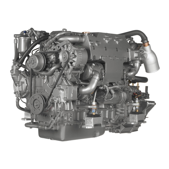
Page 15: Names Of Parts
2.3 Names of parts [Note] This illustration shows the 4LHA-HTP engine. - Page 16 [Note] This illustration shows the 4LHA-DTP engine.
- Page 17 [Note] This illustration shows the 4LHA-HTZP engine.
-
Page 18: Major Servicing Parts
Fuel filter (for 4LHA-HTP/HTZP). For 4LHA-DTP/-DTZP/-STP/-STZP, drain the dust and water periodicaly removing the drain plug at the bottom of filter. Feeds fuel to the fuel injection pump builting-in the fuel injection pump (4LHA-HTP/- Fuel feed pump HTZP). For 4LHA-DTP/-DTZP/-STP/STZP, it is attached with the fuel injection pump. -
Page 19: Control Equipment
2.5 Control Equipment The control equipment consists of the control panel and remote control handle, which are connected by the wires and cables to the control levers for remote control operation. Control Panel (Optional) 2.5.1 The control panel has the following gauges and alarm devices (optional accessories): Available , Not available No. - Page 20 START PRESS. CHARGE TEMP LEVEL PREHEAT FUEL GEAR BOOST EXHAUST FILTER Available switches (for alarm) and senders (for meter) 4LHA-HTP 4LHA-HTZP 4LHA-DTP 4LHA-DTZP 4LHA-STP 4LHA-STZP Battery not charge C.W.high temperature L.O low pressure C.W. level Exhaust (C.S.W flow) Boost Gear oil (Stern)
- Page 21 (1) Gauges and Equipment Gauges & Equipment Functions OFF: The switch key can be inserted or removed. Starter switch All power is turned off. Before starting during operation ON: For engine operation. Gauges and alarm devices are turned on. GLOW Release your hold when START: For engine starting.
- Page 22 (2) Functions of Alarm Devices (Alarm Buzzer & Lamps) The alarm buzzer sounds when any warning lamp (except the charge lamp) comes on. Warning lamps come on when sensors (switchs) detect an abnormality during engine operation. The warning lamps in the display column of the control panel are off during normal operation, but come on as follows when an abnormality arises: Charge Lamp The lamp comes on when there is a charging failure.
-
Page 23: Remote Control Handle
Function of Alarm Devices Before starting After Starting Key Operation START Alarm Buzzer Alarm Lamps Charge Lamp Cooling Water Temperature Engine Oil Pressure Fuel filter Gear Oil Boost 2.5.2 Remote Control Handle This engine is controlled by the remote control handle located in the cockpit. The speed control lever on the engine side and clutch lever on the marine drive are connected by remote control cable with the remote control handle in the cockpit. - Page 24 Starting and stopping MT-3 Put the handle in NEUTRAL. This puts the clutch in the disengage position (stop) and idles the engine at a low speed. Forward Move the handle from NEUTRAL to FWD (forward). This engages the clutch in forward and simultaneously increases the engine speed.
-
Page 25: Before Operation
3. BEFORE OPERATION 3.1 Fuel Oil, Lube Oil & Cooling Water 3.1.1 Fuel [NOTICE] Use of fuels not recommended in this Operation Manual may cause a decrease in engine performance and cause components to fail. (1) Selection of fuel Use the following diesel fuels for best engine performance: ISO8217 DMA, BS2869 A1 or A2 Fuels equivalent to Japanese Industrial Standard, JIS. -
Page 26: Lube Oil
Quicksilver is registered trademark of Brunswick Corporatoin. For further more instructions, refer to the maker's manual. Follow the maker's instructions for the marine gears. HSW450A2 (HURTH)(4LHA-HTP/-DTP) HSW630A1 (HURTH)(4LHA-STP) 3.1.3 Cooling Water [NOTICE] Be sure to add Long Life Coolant /Antifreeze (LLC) to cooling fresh water. - Page 27 2) Choose LLC which will not have any adverse effects on the materials (cast iron, aluminum, copper, etc.) of the engine's fresh water cooling system. Consult your Yanmar dealer or distributor on the use of coolant /antifreeze, and detergents. The coolans /antifreezes, which are good performance for example, are shown below.
-
Page 28: Supplying Fuel
3.2 Supplying Fuel DANGER Fires from Oil Ignition Be sure to use the correct type of fuel when refueling. Mistakenly filling with gasoline or the like will result in ignition. Be sure to stop the engine before refueling. If you spill fuel, wipe such spillage carefully. Never place oils or other flammable material close to the engine as this could result in ignition. -
Page 29: Supplying Engine Lube Oil
4LHA-HTP/-HTZP Open the cock on the fuel oil inlet pipe line. Loosen the air bleeding screw on the fuel filter Air bleeding by turning 2~3 times to the counter-clockwise screw using a screw driver. Feed the fuel with the priming pump. -
Page 30: Supplying Marine Drive Oil
3.4 Supplying Marine Drive Oil Marine gear (HSW450A2, HSW630A1) [NOTICE] For the marine gear, follow the maker's Do not overfill. instructions. Overfilling will cause oil to be sprayed out during operation and effect the For MERCRUISER's stern-driven device (BRAVO), efficiency of the marine drive. supply lube oil in accordance with the maker's instructions. -
Page 31: Supplying Cooling Water
Supply until the water overflows from the filler port. Fresh water cooler For 4LHA-HTP/-HTZP Oil cooler After supplying cooling water, fasten the filler cap firmly. If loose, trouble will occur due to water leakage. -
Page 32: Cranking
Check the rubber hose connecting the subtank to with the fresh water tank. If the hose is not water-tight a lot of coolling water will be con- sumed. 3.6 Cranking When the engine is being used for the first time or if it has not been used for a long period of time, perform cranking before starting to distribute oil to all of the parts. -
Page 33: Checking The Lube Oil And Cooling Water
3.7 Checking the Lube Oil and Cooling Water When lube oil, gear oil, and cooling water are put in for the first time, or after they have been replaced, their levels should be checked after a trial operation. Oil and water will be distributed to the various parts during the operation, lowering the levels of oil and water. -
Page 34: How To Operate
4. HOW TO OPERATE WARNING Alcohol Never operate the engine while you are under the influence of alcohol or when you are ill or feel unwell as this results in accidents. WARNING Exhaust Gas Poisoning Be sure to establish good ventilation in the engine room with windows, vents, or other ventilation equipment. - Page 35 If the cooling water runs out too often, or if the water level in the fresh water tank falls without any change in the subtank water level, there may be some leakage of water or air. In such cases, consult your Yanmar dealer or distributor without delay. (6) Checking the Remote Control Handle Be sure to check that the remote control handle lever moves smoothly before use.
-
Page 36: Checking The Control Panel And Alarm Devices
4.2 Checking the Control Panel and Alarm Devices Be sure to check the alarm devices and other instruments on the panel before and after starting the engine. If the devices are not working properly, it is impossible to prevent any problems arising from insufficient oil and water in the engine. -
Page 37: Restarting After Starting Failure
4.3.3 Restarting After Starting Failure When attempting to restart the engine after starting failure, be sure that the engine is at a complete stop before turning the starter switch key. If the engine is restarted while the engine still has not stopped, the pinion gear of the starter motor will be damaged. -
Page 38: Adjusting The Engine Speed
4.4 Adjusting the Engine Speed Adjust the speed of the engine by moving the [NOTICE] remote control handle slowly and smoothly. Move For a new engine be especially careful not to change speeds abruptly or attach the handle forward and adjust the speed between a heavy load for the first 50 hours of low speed and high speed. -
Page 39: Check During Operation
4.6 Check During Operation Always be on the look out for problems during engine operation. Pay particular attention to the following. (1) Is sufficient water being discharged from the seawater outlet pipe ? If the discharge is small, stop the engine immediately, identify the cause and repair. (2) Is the exhaust color normal ? The continuous black exhaust smoke shows engine overloading. -
Page 40: Stopping The Engine
4.7 Stopping the Engine Stop the engine in accordance with the following [NOTICE] procedures. Stopping the engine suddenly after Stop the boat. operating at high speed without cool- Put the remote control handle in NEUTRAL to ing it down will cause the engine tem- stop the boat. -
Page 41: Operation Procedure
4.8 Operation Procedure The following diagram shows the procedures for operation explained up to this point. Parts of the operation may differ depending on the marine drive and remote control system being used. Accompanying operation manuals should be read carefully and understood. Inspection Before Starting Starting Operation Starting the Engine... -
Page 42: Long-Term Storage
Loosen the bolts (4) on the side cover of the seawater pump and move the cover to drain off the cooling seawater inside. After draining off the water, tighten the water drain cocks and reinstall the side cover on the seawater pump. Seawater Oil cooler Loosen bolts Inter cooler Seawater pump Fresh water cooler For 4LHA-HTP/-HTZP... -
Page 43: Checking The Engine For Reuse After A Long Storage Period
Fresh water cooler Fresh water cooler For 4LHA-HTP/-HTZP (3) Cleaning, Draining Fuel Oil, Greasing Clean the outside of the engine wiping off any dust or oil. To prevent condensation inside the fuel tank, either drain off the fuel or fill the tank. -
Page 44: Maintenance & Inspection
5. MAINTENANCE & INSPECTION Conduct Periodic Inspection for Your Safety. The functions of engine components will degenerate and engine performance will fall according to the use of the engine. If periodic inspections are not performed, you may encounter unexpected troubles while cruising at sea, and consumption of fuel or lube oil may become excessive and exhaust gas and engine noise may increase. -
Page 45: List Of Periodic Inspections
5.1 List of Periodic Inspections Daily and periodic inspection are important to keep the engine in its best condition. The following is a summary of inspection and servicing items by inspection interval. Periodic inspection intervals vary depending on the uses, loads, fuels and lube oils used and handling conditions, and are hard to establish definitively. -
Page 46: Periodic Inspection Items
5.2 Periodic Inspection Items 5.2.1 Inspection After Initial 50Hrs. Operation (1) Replacing the Engine Lube Oil and Lube Oil Filters (1st time) CAUTION Precautions for Removing Hot Oil to Prevent Burns If extracting oil from the engine while it is still hot, do not let the oil splash on you. -
Page 47: Inspection Every 50Hours
5.2.2 Inspection Every 50 Hours (1) Draining the Fuel Tank (local supply) Put a pan under the drain to catch the fuel. Loosen the drain cock at the bottom of the fuel tank, and drain off any water and dirt collected inside. - Page 48 Drain periodically to keep the filter from becoming clogged. When there is a lot of drain collected in the oil/water separator at the bottom of the fuel filter, the fuel filter alarm lamp on the control panel (optional) will light up. (4LHA-HTP/-HTZP) 1) 4LHA-HTP/-HTZP Close the fuel cock on the fuel pipe line.
- Page 49 [NOTICE] The capacity of the specified alternator and battery is sufficient for regular operation, however, the capacity may be insufficient, if they are used for other purposes such as lights inside the boat, etc. Consult your Yanmar dealer or distributor.
-
Page 50: Inspection Every 250 Hrs. Or 1 Yr
5.2.3 Inspection Every 250 Hrs. or 1 yr. (1) Replacing the Fuel Filter 1) 4LHA-HTP/-HTZP Close the fuel cock of the fuel tank. Drain the fuel from the fuel drain cock at the bottom of fuel filter. See. 5.2.2(3) Fuel filter... - Page 51 (2) Replacing Engine Lube Oil and Lube Oil filter. (See 5.2.1(1)) (3) Replacing Cooling Fresh Water Cooling performance drops when the cooling water is contaminated with rust and scale. Even if LLC is added, the cooling water must be periodically replaced because the properties of the agent will degenerate.
- Page 52 (idle) position. If either the high speed or the low speed side does not make contact with stopper. adjust as follows: Setteng bolts (4LHA-HTP/-HTZP) Remove the threaded area and the con- necting pivot of the remote control cable Setteng bolts from the governor lever.
- Page 53 Inspection and adjustment must be made to correct opening/closing timing lags of the intake/ exhaust valves which might arise due to initial parts wear. This inspection requires specialized knowledge and techniques. Consult your Yanmar dear or distributor. 8 Inspection and Adjustment of Fuel Injection Valve (1st Time) lnspection and adjustment are necessary to obtain optimal fuel injection to ensure the good engine performance.
-
Page 54: Inspection Every 500 Hrs.or 2 Yrs
5.2.5 Inspection Every 1000 Hrs. or 4 yrs. (1) Adjustment of Intake/Exhaust Valve clearance (2nd time & after) This maintenance requires specialized knowledge. Consult your Yanmar dealer or distributor. Adjustment is necessary to maintain the correct timing for the opening and closing of valves. -
Page 55: Inspection Every 2000 Hrs
1 Cracks and loss of impeller ; flaws or excessive wear of impeller tips and side faces. If any, replace the damaged part (consult Yanmar dealer or distributor) (Note) The impeller must be replaced periodically (every 2000 hours). - Page 56 Adjustment necessary to maintain proper contact of valves and seats. This maintenance requires specialized knowledge. Consult your Yanmar dealer or distributor. (3) Inspection and Adjustment of Fuel Injection Timing Fuel injection timing must be adjusted to ensure optimal engine performance.
-
Page 57: Trouble And Troubleshooting
Drain excessive in the Drain the water in the 5.2.2(3) Lamp goes on W/O separator W/O separator of the (4LHA-HTP/-HTZP) fuel filter [NOTICE] Warning Devices Do not run the engine with alarm devices still unrepaired. are Faulty. Trouble will progress and a serious problems may result. - Page 58 Reference Trouble Probable Cause Measure Charge lamp does V-belt broken or loose Replace V-belt; adjust 5.2.4(1) not go out tension during operation Battery defective. Check fluid level, specific gravity; replace. 5.2.2(4) Alternator power Ask for repairs. generation failure Starter works No fuel Resupply fuel;...
-
Page 59: System Diagrams
7. SYSTEM DIAGRAMS 7.1 Piping diagram 4LHA-HTP... - Page 60 4LHA-HTZP...
- Page 61 4LHA-DTP/-STP...
- Page 62 4LHA-DTZP/-STZP...
-
Page 63: Wiring Diagram
7.2 Wiring diagram (1) New B-type Control panel... - Page 64 (2) New C-type Control panel...
- Page 65 (3) New D-type Control panel...
-
Page 66: Warranty Service
If the problem has already been reviewed with the Service Manager, contact the owner of the dealership or the General Manager. If your problem still has not been resolved to your satisfaction, contact your Yanmar local Subsidiary Company. - Page 67 YANMAR EUROPE B.V. BRUGPLEIN 11, 1332 BS ALMERE-DE VAART, THE NETHERLANDS P. O. BOX 30112, 1303 TEL : 31-36-5493200 FAX : 31-36-5493209 YANMAR ASIA ( SINGAPORE ) CORPORATION PTE LTD. 4 TUAS LANE. SINGAPORE 638613 TEL : 65-861-3855 FAX : 65-862-5195...
Need help?
Do you have a question about the 4LHA-HTP and is the answer not in the manual?
Questions and answers